Table of Contents

Related Manuals for IEI Technology KINO-ABT-i2 Series


Summary of Contents for IEI Technology KINO-ABT-i2 Series
- Page 1 KINO-ABT-i2 Mini-ITX SBC MODEL: KINO-ABT-i2 Series Mini-ITX SBC with 22nm Intel® Atom™ or Celeron® SoC, Dual GbE, DDR3, HDMI, VGA, DisplayPort, USB 3.0, COM, SATA 3Gb/s, IPMI 2.0 and RoHS User Manual Page i Rev. 1.02 – June 29, 2017...
- Page 2 KINO-ABT-i2 Mini-ITX SBC Revision Date Version Changes June 29, 2017 1.02 Clarified BIOS specifications February 16, 2016 1.01 Clarified memory specifications August 28, 2014 1.00 Initial release Page ii...
- Page 3 KINO-ABT-i2 Mini-ITX SBC Copyright COPYRIGHT NOTICE The information in this document is subject to change without prior notice in order to improve reliability, design and function and does not represent a commitment on the part of the manufacturer. In no event will the manufacturer be liable for direct, indirect, special, incidental, or consequential damages arising out of the use or inability to use the product or documentation, even if advised of the possibility of such damages.
- Page 4 KINO-ABT-i2 Mini-ITX SBC Manual Conventions WARNING Warnings appear where overlooked details may cause damage to the equipment or result in personal injury. Warnings should be taken seriously. CAUTION Cautionary messages should be heeded to help reduce the chance of losing data or damaging the product. NOTE These messages inform the reader of essential but non-critical information.
-
Page 5: Table Of Contents
KINO-ABT-i2 Mini-ITX SBC Table of Contents 1 INTRODUCTION......................1 1.1 I ......................2 NTRODUCTION 1.2 M ....................3 ODEL ARIATIONS 1.3 B ........................4 ENEFITS 1.4 F ........................4 EATURES 1.5 C ......................5 ONNECTORS 1.6 D ....................... 6 IMENSIONS 1.7 D ........................ - Page 6 KINO-ABT-i2 Mini-ITX SBC 3.2.9 Fan Connector (System) .................. 27 3.2.10 Front Panel Connector .................. 28 3.2.11 iRIS Module Slot..................... 29 3.2.12 Keyboard and Mouse Connector ..............30 3.2.13 LAN LED Connectors ..................31 3.2.14 Memory Card Slot(s)..................32 3.2.15 PCIe x4 Slot ....................33 3.2.16 PCIe Mini Card Slot ..................
- Page 7 KINO-ABT-i2 Mini-ITX SBC 4.3.1 AT/ATX Power Mode Setting ................61 4.3.2 Clear CMOS Button..................62 4.3.3 Flash Descriptor Security Override..............62 4.3.4 mSATA/SATA Selection..................63 4.3.5 USB Power Select .................... 63 4.4 I ............64 NTERNAL ERIPHERAL EVICE ONNECTIONS 4.4.1 SATA Drive Connection ................... 64 4.4.2 USB Cable Connection ..................
- Page 8 KINO-ABT-i2 Mini-ITX SBC 5.4.2 South Bridge....................101 5.4.2.1 Azalia HD Audio..................103 5.4.2.2 PCI Express Configuration ..............104 5.5 S ....................... 105 ECURITY 5.6 B ........................106 5.7 E ........................108 6 SOFTWARE DRIVERS .....................110 6.1 A ................111 VAILABLE OFTWARE RIVERS 6.2 S ..................111...
- Page 9 KINO-ABT-i2 Mini-ITX SBC List of Figures Figure 1-1: KINO-ABT-i2 ........................2 Figure 1-2: Connectors ........................5 Figure 1-3: KINO-ABT-i2 Main Dimensions (mm)................6 Figure 1-4: Data Flow Diagram......................7 Figure 3-1: Connectors and Jumpers..................17 Figure 3-2: ATX Power Connector Location ................20 Figure 3-3: Audio Connector Location ..................21 Figure 3-4: Battery Connector Location..................22 Figure 3-5: Chassis Intrusion Connector Location..............23 Figure 3-6: Digital I/O Connector Location ................24...
- Page 10 KINO-ABT-i2 Mini-ITX SBC Figure 3-27: SPI EC Flash Connector Location.................45 Figure 3-28: TPM Connector Location..................46 Figure 3-29: USB 2.0 Connector Locations ................47 Figure 3-30: External Peripheral Interface Connector ..............48 Figure 3-31: Audio Connector .....................49 Figure 3-32: Ethernet Connector....................50 Figure 3-33: Ethernet Connector....................51 Figure 3-34: HDMI Connector ......................52 Figure 3-35: Serial Port Pinouts ....................53 Figure 3-36: VGA Connector .......................54...
- Page 11 KINO-ABT-i2 Mini-ITX SBC Figure 6-14: System Control Panel ..................120 Figure 6-15: Device Manager List .................... 121 Figure 6-16: Update Driver Software Window ................ 122 Figure 6-17: Locate Driver Files ....................122 Page xi...
- Page 12 KINO-ABT-i2 Mini-ITX SBC List of Tables Table 1-1: Model Variations ......................3 Table 1-2: KINO-ABT-i2 Specifications..................10 Table 2-1: Packing List.........................14 Table 2-2: Optional Items......................15 Table 3-1: Peripheral Interface Connectors ................19 Table 3-2: Rear Panel Connectors ....................19 Table 3-3: ATX Power Connector Pinouts .................21 Table 3-4: Audio Connector Pinouts ..................21 Table 3-5: Battery Connector Pinouts ..................22 Table 3-6: Chassis Intrusion Connector Pinouts ..............23...
- Page 13 KINO-ABT-i2 Mini-ITX SBC Table 3-27: TPM Connector Pinouts ...................46 Table 3-28: USB1 Pinouts ......................47 Table 3-29: USB2 Pinouts ......................47 Table 3-30: LAN2 Ethernet Connector Pinouts .................49 Table 3-31: Connector LEDs......................50 Table 3-32: USB 2.0 Port Pinouts....................50 Table 3-33: LAN1 Ethernet Connector Pinouts .................51 Table 3-34: Connector LEDs......................51 Table 3-35: USB 3.0 Port Pinouts....................51 Table 3-36: HDMI Connector Pinouts ..................52...
- Page 14 KINO-ABT-i2 Mini-ITX SBC BIOS Menus BIOS Menu 1: Main ........................72 BIOS Menu 2: Advanced ......................74 BIOS Menu 3: ACPI Configuration ....................75 BIOS Menu 4: Super IO Configuration..................76 BIOS Menu 5: Serial Port n Configuration Menu...............76 BIOS Menu 6: iWDD Hardware Monitor ..................85 BIOS Menu 7: Smart Fan Function .....................86 BIOS Menu 8: RTC Wake Settings ....................88 BIOS Menu 9: Serial Port Console Redirection .................90...
-
Page 15: Introduction
KINO-ABT-i2 Mini-ITX SBC Chapter Introduction Page 1... -
Page 16: Introduction
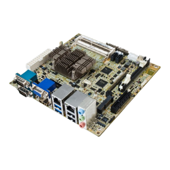
KINO-ABT-i2 Mini-ITX SBC 1.1 Introduction Figure 1-1: KINO-ABT-i2 The KINO-ABT-i2 is a Mini-ITX form factor single bard computer. It has an on-board 22nm Intel® Atom™ or Celeron® processor, and supports one/two 204-pin 1333/1066 MHz dual-channel unbuffered DDR3 Low Voltage (DDR3L) SDRAM SO-DIMM with up to 4.0 GB / 8.0 GB of memory. -
Page 17: Model Variations
KINO-ABT-i2 Mini-ITX SBC 1.2 Model Variations There are eight models of the KINO-ABT-i2 series. The model variations are listed in Table 1-1. Model On-board SoC DDR3L Memory Standard KINO-ABT-i2-J19001 Intel® Celeron® processor J1900 2 x SO-DIMM slots (2 GHz, quad-core, 2 MB cache) Size: 8 GB (max.) -
Page 18: Benefits
KINO-ABT-i2 Mini-ITX SBC 1.3 Benefits Some of the KINO-ABT-i2 motherboard benefits include: Powerful graphics with multiple monitors Staying connected with both wired LAN connections Speedy running of multiple programs and applications 1.4 Features Some of the KINO-ABT-i2 motherboard features are listed below: ... -
Page 19: Connectors
KINO-ABT-i2 Mini-ITX SBC 1.5 Connectors The connectors on the KINO-ABT-i2 are shown in the figure below. *DIMM2 slot is only available on J1900, N2930, E3845, E3827 and E3826 models. For detailed information, please refer to Section 3.2.14. Figure 1-2: Connectors Page 5... -
Page 20: Dimensions
KINO-ABT-i2 Mini-ITX SBC 1.6 Dimensions The main dimensions of the KINO-ABT-i2 are shown in the diagram below. Figure 1-3: KINO-ABT-i2 Main Dimensions (mm) Page 6... -
Page 21: Data Flow
KINO-ABT-i2 Mini-ITX SBC 1.7 Data Flow F igure 1-4 shows the data flow between the system chipset, the CPU and other components installed on the motherboard. Figure 1-4: Data Flow Diagram Page 7... -
Page 22: Technical Specifications
KINO-ABT-i2 Mini-ITX SBC 1.8 Technical Specifications KINO-ABT-i2 technical specifications are listed below. Specification/Model KINO-ABT-i2 Form Factor Mini-ITX Standard On-board SoC Intel® Celeron® processor J1900 (2GHz, quad-core, 2MB cache, TDP=10W) Intel® Celeron® processor N2930 (1.83GHz, quad-core, 2MB cache, TDP=7.5W) Intel® Celeron® processor N2807 (1.58GHz, dual-core, 2MB cache, TDP=4.5W) ... - Page 23 KINO-ABT-i2 Mini-ITX SBC Specification/Model KINO-ABT-i2 Integrated Graphics Intel® HD Graphics Gen7 with 4 execution units, supporting DirectX 11.1, OpenCL 1.2 and OpenGL 4.2 Audio Realtek ALC662 HD Audio codec BIOS UEFI BIOS AIxx BIOS version is for Bay Trail I model (CPU: E38xx) ...
-
Page 24: Table 1-2: Kino-Abt-I2 Specifications
KINO-ABT-i2 Mini-ITX SBC Specification/Model KINO-ABT-i2 Keyboard/Mouse One internal keyboard/mouse connector Serial Ports One RS-422/485 via internal wafer connector Three RS-232 via internal pin headers Two RS-232 via D-sub 9 connector USB ports Two external USB 3.0 ports Two external USB 2.0 ports Four USB 2.0 ports by two 8-pin headers Serial ATA Two SATA 3Gb/s connectors with two 5 V SATA power connectors... -
Page 25: Packing List
KINO-ABT-i2 Mini-ITX SBC Chapter Packing List Page 11... -
Page 26: Anti-Static Precautions
KINO-ABT-i2 Mini-ITX SBC 2.1 Anti-static Precautions WARNING! Static electricity can destroy certain electronics. Make sure to follow the ESD precautions to prevent damage to the product, and injury to the user. Make sure to adhere to the following guidelines: Wear an anti-static wristband: Wearing an anti-static wristband can prevent electrostatic discharge. -
Page 27: Packing List
KINO-ABT-i2 Mini-ITX SBC 2.3 Packing List NOTE: If any of the components listed in the checklist below are missing, do not proceed with the installation. Contact the IEI reseller or vendor the KINO-ABT-i2 was purchased from or contact an IEI sales representative directly by sending an email to s ales@ieiworld.com The KINO-ABT-i2 is shipped with the following components:... -
Page 28: Optional Items
KINO-ABT-i2 Mini-ITX SBC Quantity Item and Part Number Image Quick Installation Guide Table 2-1: Packing List 2.4 Optional Items The following are optional components which may be separately purchased: Item and Part Number Image IPMI 2.0 adapter card with AST2400 BMC chip (P/N: iRIS-2400-R10) Dual USB cable (P/N: 32000-070301-RS) -
Page 29: Table 2-2: Optional Items
KINO-ABT-i2 Mini-ITX SBC Item and Part Number Image DisplayPort to DVI-D converter board for iEi IDP connector (P/N: DP-DVI-R10) DisplayPort to HDMI converter board for IEI IDP connector (P/N: DP-HDMI-R10) DisplayPort to 24-bit dual-channel LVDS converter board for iEi IDP connector (P/N: DP-LVDS-R10) DisplayPort to VGA converter board for IEI IDP connector (P/N: DP-VGA-R10) -
Page 30: Connectors
KINO-ABT-i2 Mini-ITX SBC Chapter Connectors Page 16... -
Page 31: Peripheral Interface Connectors
KINO-ABT-i2 Mini-ITX SBC 3.1 Peripheral Interface Connectors This chapter details all the jumpers and connectors. 3.1.1 KINO-ABT-i2 Layout The figures below show all the connectors and jumpers. *DIMM2 slot is only available on J1900, N2930, E3845, E3827 and E3826 models. For detailed information, please refer to Section 3.2.14. -
Page 32: Peripheral Interface Connectors
KINO-ABT-i2 Mini-ITX SBC 3.1.2 Peripheral Interface Connectors The table below lists all the connectors on the board. Connector Type Label ATX power input connector 24-pin connector ATX1 Audio connector 10-pin header FRONT-PANEL1 Battery connector 2-pin wafer BAT1 Chassis intrusion connector 2-pin header CHASSIS1 Digital I/O connector... -
Page 33: External Interface Panel Connectors
KINO-ABT-i2 Mini-ITX SBC Connector Type Label SATA power connectors (5 V) 2-pin wafer SATA_PWR1, SATA_PWR2 Serial ports, RS-232 10-pin header COM3, COM5, COM6 Serial port, RS-422/485 4-pin wafer COM4 SMBus connector 4-pin wafer SPDIF connector 5-pin header SPDIF1 SPI flash connector 6-pin wafer JSPI1 SPI flash connector (EC) -
Page 34: Internal Peripheral Connectors
KINO-ABT-i2 Mini-ITX SBC 3.2 Internal Peripheral Connectors The section describes all of the connectors on the KINO-ABT-i2. 3.2.1 ATX Power Connector CN Label: ATX1 CN Type: 24-pin connector, p=4.2 mm CN Location: See Figure 3-2 CN Pinouts: See Table 3-3 The ATX power input connector provides power to the system. -
Page 35: Audio Connector
KINO-ABT-i2 Mini-ITX SBC Description Description +12 V +5 V +12 V +5 V +3.3 V Table 3-3: ATX Power Connector Pinouts 3.2.2 Audio Connector CN Label: FRONT-PANEL1 CN Type: 10-pin header, p=2.54 mm CN Location: See Figure 3-3 CN Pinouts: See Table 3-4 This connector connects to speakers, a microphone and an audio input. -
Page 36: Battery Connector
KINO-ABT-i2 Mini-ITX SBC 3.2.3 Battery Connector CAUTION: Risk of explosion if battery is replaced by an incorrect type. Only certified engineers should replace the on-board battery. Dispose of used batteries according to instructions and local regulations. CN Label: BAT1 CN Type: 2-pin wafer, p=1.25 mm CN Location: See Figure 3-4... -
Page 37: Chassis Intrusion Connector
KINO-ABT-i2 Mini-ITX SBC 3.2.4 Chassis Intrusion Connector CN Label: CHASSIS1 CN Type: 2-pin header, p=2.54 mm CN Location: F igure 3-5 CN Pinouts: See Table 3-6 The chassis intrusion connector is for a chassis intrusion detection sensor or switch that detects if a chassis component is removed or replaced. -
Page 38: Displayport Connector
KINO-ABT-i2 Mini-ITX SBC The digital I/O connector provides programmable input and output for external devices. The digital I/O provides 4-bit output and 4-bit input. Figure 3-6: Digital I/O Connector Location PIN NO. DESCRIPTION PIN NO. DESCRIPTION DOUT3 DOUT2 DOUT1 DOUT0 DIN3 DIN2 DIN1... -
Page 39: Ec Debug Connector
KINO-ABT-i2 Mini-ITX SBC Figure 3-7: DisplayPort Connector Location Description Description LANE3N AUXP AUXN LANE0P AUX_CTRL_DET_D LANE1P LANE0N LANE1N LANE2P +3.3V LANE3P LANE2N Table 3-8: DisplayPort Connector Pinouts 3.2.7 EC Debug Connector CN Label: CN Type: 18-pin header, p=2.00 mm CN Location: See Figure 3-8 CN Pinouts: See Table 3-9... -
Page 40: Fan Connector (Cpu)
KINO-ABT-i2 Mini-ITX SBC Figure 3-8: EC Debug Connector Location Description Description EC_EPP_STB# EC_EPP_AFD# EC_EPP_PD0 EC_EPP_PD1 EC_EPP_INIT# EC_EPP_PD2 EC_EPP_SLIN# EC_EPP_PD3 EC_EPP_PD4 EC_EPP_PD5 EC_EPP_BUSY EC_EPP_PD6 EC_EPP_KSI5 EC_EPP_PD7 EC_EPP_KSI4 Table 3-9: EC Debug Connector Pinouts 3.2.8 Fan Connector (CPU) CN Label: CPU_FAN1 CN Type: 4-pin wafer, p=2.54 mm CN Location: See Figure 3-9... -
Page 41: Fan Connector (System)
KINO-ABT-i2 Mini-ITX SBC Figure 3-9: CPU Fan Connector Location PIN NO. DESCRIPTION +12 V FAN_IO Table 3-10: CPU Fan Connector Pinouts 3.2.9 Fan Connector (System) CN Label: SYS_FAN1 CN Type: 4-pin wafer, p=2.54 mm CN Location: See Figure 3-10 CN Pinouts: See Table 3-11 Each fan connector attaches to a system cooling fan. -
Page 42: Front Panel Connector
KINO-ABT-i2 Mini-ITX SBC Figure 3-10: System Fan Connector Location PIN NO. DESCRIPTION +12 V FAN_IO Table 3-11: System Fan Connector Pinouts 3.2.10 Front Panel Connector CN Label: F_PANEL1 CN Type: 14-pin header, p=2.54 mm CN Location: See Figure 3-11 CN Pinouts: See Table 3-12 The front panel connector connects to the indicator LEDs and buttons on the computer's front panel. -
Page 43: Iris Module Slot
KINO-ABT-i2 Mini-ITX SBC Figure 3-11: Front Panel Connector Location FUNCTION DESCRIPTION FUNCTION DESCRIPTION Power LED PWR_LED+ Speaker Speaker+ IPMI LED IPMI_LED+ PWR_LED- IPMI_LED- Power Button PWR_BTN+ Speaker Speaker- PWR_BTN- HDD LED HDD_LED+ Reset Button Reset+ HDD_LED- Reset- Table 3-12: Front Panel Connector Pinouts 3.2.11 iRIS Module Slot CN Label: IPMI1... -
Page 44: Keyboard And Mouse Connector
KINO-ABT-i2 Mini-ITX SBC WARNING: The iRIS module slot is designed to install the IEI iRIS-2400 IPMI 2.0 module only. DO NOT install other modules into the iRIS module slot. Doing so may cause damage to the KINO-ABT-i2. Figure 3-12: iRIS Module Slot Location 3.2.12 Keyboard and Mouse Connector CN Label: KB_MS1... -
Page 45: Lan Led Connectors
KINO-ABT-i2 Mini-ITX SBC Figure 3-13: Keyboard and Mouse Connector Location Description Mouse Data Mouse Clock Keyboard Data Keyboard Clock Table 3-13: Keyboard and Mouse Connector Pinouts 3.2.13 LAN LED Connectors CN Label: LED_LAN1, LED_LAN2 CN Type: 2-pin header, p=2.54 mm CN Location: F igure 3-14 CN Pinouts:... -
Page 46: Memory Card Slot(S)
KINO-ABT-i2 Mini-ITX SBC Figure 3-14: LAN LED Connector Locations Description +3.3 V LAN1_LINK_ACT- Table 3-14: LAN1 LED Connector Pinouts Description +3.3 v LAN2_LINK_ACT- Table 3-15: LAN2 LED Connector Pinouts 3.2.14 Memory Card Slot(s) CN Label: DIMM1, DIMM2 CN Type: DDR3 SO-DIMM slot CN Location: F igure 3-15 The SO-DIMM slots are for installing DDR3 Low Voltage SO-DIMM memory modules. -
Page 47: Pcie X4 Slot
KINO-ABT-i2 Mini-ITX SBC For J1900, N2930, E3845, E3827 and E3826 SKUs: Two 204-pin 1333/1066 MHz dual-channel unbuffered DDR3L SDRAM SO-DIMM slots (DIMM1 and DIMM2) support up to 8 GB of memory For N2807, E3825 and E3815 SKUs: One 204-pin 1333/1066 MHz unbuffered DDR3L SDRAM SO-DIMM slot (DIMM1) supports up to 4 GB of memory NOTE: Use DIMM1 slot when installing one SO-DIMM. -
Page 48: Pcie Mini Card Slot
KINO-ABT-i2 Mini-ITX SBC Figure 3-16: PCIe x4 Slot Location 3.2.16 PCIe Mini Card Slot CN Label: CN Type: PCIe Mini card slot CN Location: F igure 3-17 CN Pinouts: See Table 3-16 The PCIe Mini card slot is for installing PCIe Mini expansion cards, such as mSATA modules or Wi-Fi modules. -
Page 49: Table 3-16: Pcie Mini Card Slot Pinouts
KINO-ABT-i2 Mini-ITX SBC Description Description PCIE_WAKE# +3.3 V +1.5 V MSATA_CLK- MSATA_CLK+ PLTRST_N +3.3 V PLTRST_N SATA_RX+ +3.3 V SATA_RX- +1.5 V SMB_CLK SATA_TX- SMBD_ATA SATA_TX+ USB_DATA- USB_DATA+ +3.3 V +3.3 V +3.3 V CLINK_CLK CLINK_DATA +1.5 V CLINK_RST# MSATA_DET +3.3 V Table 3-16: PCIe Mini Card Slot Pinouts Page 35... -
Page 50: Power Button
KINO-ABT-i2 Mini-ITX SBC 3.2.17 Power Button CN Label: PWR_SW1 CN Type: Push button CN Location: See Figure 3-18 The on-board power button controls system power. Figure 3-18: Power Button Location 3.2.18 Reset Button Connector CN Label: RST_BTN1 CN Type: 2-pin wafer, p=2.00 mm CN Location: See Figure 3-19 CN Pinouts:... -
Page 51: Sata 3Gb/S Drive Connectors
KINO-ABT-i2 Mini-ITX SBC Figure 3-19: Reset Button Connector Location Description PM_SYSRST_R# Table 3-17: Reset Button Connector Pinouts 3.2.19 SATA 3Gb/s Drive Connectors CN Label: SATA1, SATA2 CN Type: 7-pin SATA drive connectors CN Location: See Figure 3-20 CN Pinouts: See Table 3-18 The SATA drive connectors can be connected to SATA drives. -
Page 52: Sata Power Connectors
KINO-ABT-i2 Mini-ITX SBC Figure 3-20: SATA 3Gb/s Drive Connector Locations Description SATA_TX+ SATA_TX- SATA_RX- SATA_RX+ Table 3-18: SATA 3Gb/s Drive Connector Pinouts 3.2.20 SATA Power Connectors CN Label: SATA_PWR1, SATA_PWR2 CN Type: 2-pin wafer, p=2.00 mm CN Location: See Figure 3-21 CN Pinouts: See Table 3-19 Use the SATA Power Connector to connect to SATA device power connections. -
Page 53: Serial Port Connectors, Rs-232
KINO-ABT-i2 Mini-ITX SBC Figure 3-21: SATA Power Connector Locations Description +5VS Table 3-19: SATA Power Connector Pinouts 3.2.21 Serial Port Connectors, RS-232 CN Label: COM3, COM5, COM6 CN Type: 10-pin header, p=2.00 mm CN Location: See Figure 3-22 CN Pinouts: See Table 3-20 The connector provides RS-232 port connection. -
Page 54: Serial Port Connector, Rs-422/485
KINO-ABT-i2 Mini-ITX SBC Figure 3-22: RS-232 Serial Port Connector Locations PIN NO. DESCRIPTION PIN NO. DESCRIPTION SOUT Table 3-20: RS-232 Serial Port Connector Pinouts 3.2.22 Serial Port Connector, RS-422/485 CN Label: COM4 CN Type: 4-pin wafer, p=2.00 mm CN Location: See Figure 3-23 CN Pinouts: See Table 3-21... -
Page 55: Figure 3-23: Rs-422/485 Connector Location
KINO-ABT-i2 Mini-ITX SBC Figure 3-23: RS-422/485 Connector Location PIN NO. DESCRIPTION RXD422- RXD422+ TXD422+/TXD485+ TXD422-/TXD485- Table 3-21: RS-422/485 Connector Pinouts Use the optional RS-422/485 cable to connect to a serial device. The pinouts of the D-sub 9 connector are listed below. RS-422 Pinouts RS-485 Pinouts Table 3-22: RS-422/485 Pinouts of D-sub 9 Connector... -
Page 56: Smbus Connector
KINO-ABT-i2 Mini-ITX SBC 3.2.23 SMBus Connector CN Label: CN Type: 4-pin wafer, p=1.25 mm CN Location: See Figure 3-24 CN Pinouts: See Table 3-23 The SMBus (System Management Bus) connector provides low-speed system management communications. Figure 3-24: SMBus Connector Location DESCRIPTION SMB_DATA SMB_CLK... -
Page 57: Spi Flash Connector
KINO-ABT-i2 Mini-ITX SBC CN Location: See Figure 3-25 CN Pinouts: See Table 3-24 Use the SPDIF connector to connect digital audio devices to the system. Figure 3-25: SPDIF Connector Location Description +5 V SPDIF OUT SPDIF IN Table 3-24: SPDIF Connector Pinouts 3.2.25 SPI Flash Connector CN Label: JSPI1... -
Page 58: Spi Flash Connector, Ec
KINO-ABT-i2 Mini-ITX SBC Figure 3-26: SPI Flash Connector Location PIN NO. DESCRIPTION PIN NO. DESCRIPTION +1.8 V SPI_CLK SPI_CS# SPI_SI SPI_SO Table 3-25: SPI Flash Connector Pinouts 3.2.26 SPI Flash Connector, EC CN Label: JSPI2 CN Type: 6-pin wafer, p=1.25 mm CN Location: See Figure 3-27 CN Pinouts:... -
Page 59: Tpm Connector
KINO-ABT-i2 Mini-ITX SBC Figure 3-27: SPI EC Flash Connector Location PIN NO. DESCRIPTION PIN NO. DESCRIPTION +1.8 V SPI_CLK SPI_CS# SPI_SI SPI_SO Table 3-26: SPI EC Flash Connector Pinouts 3.2.27 TPM Connector CN Label: TPM1 CN Type: 20-pin header, p=2.54 mm CN Location: See Figure 3-28 CN Pinouts:... -
Page 60: Usb 2.0 Connectors
KINO-ABT-i2 Mini-ITX SBC Figure 3-28: TPM Connector Location Description Description LPC_CLK LPC_FRAME# BUF_PLT_RST# LPC_AD3 LPC_AD2 +3.3V LPC_AD1 LPC_AD0 SMB_CLK SMB_DATA +3.3 V INT_SERIRQ PM_GLKRUN# +3.3 V TPM_DRQ# Table 3-27: TPM Connector Pinouts 3.2.28 USB 2.0 Connectors CN Label: USB1, USB2 CN Type: 8-pin header, p=2.00 mm CN Location:... -
Page 61: Figure 3-29: Usb 2.0 Connector Locations
KINO-ABT-i2 Mini-ITX SBC The USB 2.0 connector connects to USB 2.0 devices. Each pin header provides two USB 2.0 ports. Figure 3-29: USB 2.0 Connector Locations PIN NO. DESCRIPTION PIN NO. DESCRIPTION +VCC_USB45 DATA4- DATA5+ DATA4+ DATA5- +VCC_USB45 Table 3-28: USB1 Pinouts PIN NO. -
Page 62: External Peripheral Interface Connector Panel
KINO-ABT-i2 Mini-ITX SBC 3.3 External Peripheral Interface Connector Panel The figure below shows the external peripheral interface connector (EPIC) panel. The EPIC panel consists of the following: Figure 3-30: External Peripheral Interface Connector 3.3.1 Audio Connector CN Label: CN13 CN Type: Audio jacks CN Location: See Figure 3-30... -
Page 63: Ethernet And Usb 2.0 Combo Connector
KINO-ABT-i2 Mini-ITX SBC Figure 3-31: Audio Connector 3.3.2 Ethernet and USB 2.0 Combo Connector CN Label: LAN2_USB2 CN Type: RJ-45 and USB 2.0 connector CN Location: See Figure 3-30 CN Pinouts: See Table 3-30 and Table 3-32 A 10/100/1000 Mb/s connection can be made to a Local Area Network. Description Description TRD2P0... -
Page 64: Ethernet And Usb 3.0 Combo Connector
KINO-ABT-i2 Mini-ITX SBC Figure 3-32: Ethernet Connector Description Description on: linked off: 10 Mb/s blinking: data is being sent/received green: 100 Mb/s orange: 1000 Mb/s Table 3-31: Connector LEDs The USB 2.0 connector can be connected to a USB 2.0 device. Description Description USB_DATA-... -
Page 65: Figure 3-33: Ethernet Connector
KINO-ABT-i2 Mini-ITX SBC Description Description LAN1_MDI0P LAN1_MDI2P LAN1_MDI0N LAN1_MDI2N LAN1_MDI1P LAN1_MDI3P LAN1_MDI1N LAN1_MDI3N Table 3-33: LAN1 Ethernet Connector Pinouts Figure 3-33: Ethernet Connector Description Description on: linked off: 10 Mb/s blinking: data is being sent/received green: 100 Mb/s orange: 1000 Mb/s Table 3-34: Connector LEDs The USB 3.0 connector can be connected to a USB device. -
Page 66: Hdmi Connector
KINO-ABT-i2 Mini-ITX SBC 3.3.4 HDMI Connector CN Label: HDMI1 CN Type: 23-pin HDMI port CN Location: See Figure 3-30 CN Pinouts: See Table 3-36 and Figure 3-34 The HDMI connector can connect to an HDMI device. The HDMI connector supports up to 2560 x 1600 resolutions. -
Page 67: Serial Port Connectors (Com1 And Com2)
KINO-ABT-i2 Mini-ITX SBC 3.3.5 Serial Port Connectors (COM1 and COM2) CN Label: COM1 CN Type: D-sub 9 CN Location: See Figure 3-30 CN Pinouts: See Table 3-37 and Figure 3-35 The serial port connects to a RS-232 serial communications device. Description Description Table 3-37: Serial Port Pinouts... -
Page 68: Figure 3-36: Vga Connector
KINO-ABT-i2 Mini-ITX SBC DESCRIPTION DESCRIPTION GREEN BLUE DDCDA HSYNC VSYNC DDCCLK Table 3-38: VGA Connector Pinouts Figure 3-36: VGA Connector Page 54... -
Page 69: Installation
KINO-ABT-i2 Mini-ITX SBC Chapter Installation Page 55... -
Page 70: Anti-Static Precautions
KINO-ABT-i2 Mini-ITX SBC 4.1 Anti-static Precautions WARNING: Failure to take ESD precautions during the installation of the KINO-ABT-i2 may result in permanent damage to the KINO-ABT-i2 and severe injury to the user. Electrostatic discharge (ESD) can cause serious damage to electronic components, including the KINO-ABT-i2. - Page 71 KINO-ABT-i2 Mini-ITX SBC WARNING: The installation instructions described in this manual should be carefully followed in order to prevent damage to the components and injury to the user. Before and during the installation please DO the following: Read the user manual: The user manual provides a complete description of the KINO-ABT-i2 installation instructions and configuration options.
-
Page 72: So-Dimm Installation
KINO-ABT-i2 Mini-ITX SBC 4.2.1 SO-DIMM Installation To install an SO-DIMM, please follow the steps below and refer to Figure 4-1. Figure 4-1: SO-DIMM Installation Step 1: Locate the SO-DIMM socket on the solder side of the KINO-ABT-i2. Place the board on an anti-static mat. Step 2: Align the SO-DIMM with the socket. -
Page 73: Figure 4-2: Iris Module Installation
KINO-ABT-i2 Mini-ITX SBC Figure 4-2: iRIS Module Installation Step 1: Locate the iRIS module slot. See Figure 3-12. Step 2: Open the socket handles. Open the two handles outwards as far as they can. See Figure 4-2. Step 3: Align the iRIS-2400 module with the socket. Align the iRIS-2400 module so the notch on the module lines up with the notch on the socket. -
Page 74: Pcie Mini Card Installation
KINO-ABT-i2 Mini-ITX SBC 4.2.3 PCIe Mini Card Installation To install the PCIe Mini card, please refer to the diagram and instructions below. NOTE: The PCIe Mini card slot supports full-size and half-size PCIe Mini cards. The following instruction diagrams take full-size cards as an example to show users how to install. -
Page 75: System Configuration
KINO-ABT-i2 Mini-ITX SBC Figure 4-4: PCIe Mini Card Installation (Full-size) 4.3 System Configuration The KINO-ABT-i2 is a jumperless single board computer. The system configuration is controlled by buttons and switches. The system configuration must be performed before installation. 4.3.1 AT/ATX Power Mode Setting The AT and ATX power mode selection is made through the AT/ATX power mode switch which is shown in Figure 4-5. -
Page 76: Clear Cmos Button
KINO-ABT-i2 Mini-ITX SBC 4.3.2 Clear CMOS Button To reset the BIOS, remove the on-board battery and press the clear CMOS button for three seconds or more. The clear CMOS button location is shown in Figure 4-6. Figure 4-6: Clear CMOS Button Location 4.3.3 Flash Descriptor Security Override The Flash Descriptor Security Override jumper (J_FLASH1) specifies whether to override the flash descriptor. -
Page 77: Msata/Sata Selection
KINO-ABT-i2 Mini-ITX SBC 4.3.4 mSATA/SATA Selection Use the J_SATA1 switch to select whether to automatically detect mSATA devices. Setting Description Automatically detect mSATA device (Default) Enable mSATA device Table 4-2: mSATA/SATA Switch Settings Figure 4-8: mSATA/SATA Switch Location 4.3.5 USB Power Select The USB power selection is made through the BIOS options in “Chipset ... -
Page 78: Internal Peripheral Device Connections
KINO-ABT-i2 Mini-ITX SBC 4.4 Internal Peripheral Device Connections This section outlines the installation of peripheral devices to the on-board connectors. 4.4.1 SATA Drive Connection The KINO-ABT-i2 is shipped with two SATA drive cables. To connect the SATA drive to the connector, please follow the steps below. Step 1: Locate the SATA connector and the SATA power connector. -
Page 79: Usb Cable Connection
KINO-ABT-i2 Mini-ITX SBC 4.4.2 USB Cable Connection The KINO-ABT-i2 is shipped with a dual port USB 2.0 cable. To connect the USB cable connector, please follow the steps below. Step 1: Locate the connectors. The locations of the USB connectors are shown in Chapter 3. -
Page 80: Ipmi Setup Procedure
KINO-ABT-i2 Mini-ITX SBC 4.5 IPMI Setup Procedure The KINO-ABT-i2 features Intelligent Platform Management Interface (IPMI) that helps lower the overall costs of server management by enabling users to maximize IT resources, save time and manage multiple systems. The KINO-ABT-i2 supports IPMI 2.0 through the optional iRIS-2400 module. -
Page 81: Figure 4-11: Iei Iman Web Address
KINO-ABT-i2 Mini-ITX SBC Step 2: On the remote management console, open a web browser. Enter the managed system IP address in the web browser (Figure 4-11). Figure 4-11: IEI iMAN Web Address Step 3: The login page appears in the web browser. Step 4: Enter the user name and password to login the system. - Page 82 KINO-ABT-i2 Mini-ITX SBC NOTE: To understand how to use the IEI iMAN Web GUI, please refer to the iRIS-2400 Web GUI user manual in the utility CD came with the KINO-ABT-i2. The user manual describes each function in detail. Page 68...
-
Page 83: Bios
KINO-ABT-i2 Mini-ITX SBC Chapter BIOS Page 69... -
Page 84: Introduction
KINO-ABT-i2 Mini-ITX SBC 5.1 Introduction The BIOS is programmed onto the BIOS chip. The BIOS setup program allows changes to certain system settings. This chapter outlines the options that can be changed. NOTE: Some of the BIOS options may vary throughout the life cycle of the product and are subject to change without prior notice. -
Page 85: Getting Help
KINO-ABT-i2 Mini-ITX SBC Function Increase the numeric value or make changes Decrease the numeric value or make changes Esc key Main Menu – Quit and not save changes into CMOS Status Page Setup Menu and Option Page Setup Menu -- Exit current page and return to Main Menu F1 key General help, only for Status Page Setup Menu and Option... -
Page 86: Main
KINO-ABT-i2 Mini-ITX SBC Security – Sets User and Supervisor Passwords. Save & Exit – Selects exit options and loads default settings The following sections completely describe the configuration options found in the menu items at the top of the BIOS screen and listed above. 5.2 Main The Main BIOS menu (BIOS Menu 1) appears when the BIOS Setup program is entered. - Page 87 KINO-ABT-i2 Mini-ITX SBC Compliency: Current compliant version Project Version: the board version Build Date and Time: Date and time the current BIOS version was made Memory Information The Memory Information lists a brief summary of the system memory. The fields in Memory Information cannot be changed.
-
Page 88: Advanced
KINO-ABT-i2 Mini-ITX SBC 5.3 Advanced Use the Advanced menu (BIOS Menu 2) to configure the CPU and peripheral devices through the following sub-menus: WARNING! Setting the wrong values in the sections below may cause the system to malfunction. Make sure that the settings made are compatible with the hardware. -
Page 89: Bios Menu 3: Acpi Configuration
KINO-ABT-i2 Mini-ITX SBC Aptio Setup Utility – Copyright (C) 2013 American Megatrends, Inc. Advanced ACPI Settings Select the highest ACPI sleep state the system ACPI Sleep State [S3 (Suspend to RAM)] will enter when the SUSPEND button is pressed. ---------------------- : Select Screen ... -
Page 90: Super Io Configuration
KINO-ABT-i2 Mini-ITX SBC 5.3.2 Super IO Configuration Use the Super IO Configuration menu (BIOS Menu 4) to set or change the configurations for the serial ports. Aptio Setup Utility – Copyright (C) 2013 American Megatrends, Inc. Advanced F81866 Super IO Configuration Set Parameters of Serial Port 1 (COMA) F81866 Super IO Chip... - Page 91 KINO-ABT-i2 Mini-ITX SBC 5.3.2.1.1 Serial Port 1 Configuration Serial Port [Enabled] Use the Serial Port option to enable or disable the serial port. Disabled Disable the serial port Enable the serial port Enabled EFAULT Change Settings [Auto] Use the Change Settings option to change the serial port IO port address and interrupt address.
- Page 92 KINO-ABT-i2 Mini-ITX SBC 5.3.2.1.2 Serial Port 2 Configuration Serial Port [Enabled] Use the Serial Port option to enable or disable the serial port. Disabled Disable the serial port Enable the serial port Enabled EFAULT Change Settings [Auto] Use the Change Settings option to change the serial port IO port address and interrupt address.
- Page 93 KINO-ABT-i2 Mini-ITX SBC IO=2E8h; Serial Port I/O port address is 2E8h and the interrupt IRQ=3, address is IRQ3, 4, 5, 6, 7, 9, 10, 11, 12 5, 6, 7, 9, 10, 11, 12 5.3.2.1.3 Serial Port 3 Configuration Serial Port [Enabled] Use the Serial Port option to enable or disable the serial port.
- Page 94 KINO-ABT-i2 Mini-ITX SBC IO=3E8h; Serial Port I/O port address is 3E8h and the interrupt IRQ=3, address is IRQ3, 4, 5, 6, 7, 9, 10, 11, 12 5, 6, 7, 9, 10, 11, 12 Serial Port I/O port address is 2E8h and the interrupt IO=2E8h;...
- Page 95 KINO-ABT-i2 Mini-ITX SBC IO=2E8h; Serial Port I/O port address is 2E8h and the interrupt IRQ=10 address is IRQ10 Serial Port I/O port address is 3F8h and the interrupt IO=3F8h; address is IRQ3, 4, 5, 6, 7, 9, 10, 11, 12 IRQ=3, 5, 6, 7, 9, 10, 11, 12...
- Page 96 KINO-ABT-i2 Mini-ITX SBC Disabled Disable the serial port Enable the serial port Enabled EFAULT Change Settings [Auto] Use the Change Settings option to change the serial port IO port address and interrupt address. Auto The serial port IO port address and interrupt address EFAULT are automatically detected.
- Page 97 KINO-ABT-i2 Mini-ITX SBC IO=2E0h; Serial Port I/O port address is 2E0h and the interrupt IRQ=3, address is IRQ3, 4, 5, 6, 7, 9, 10, 11, 12 5, 6, 7, 9, 10, 11, 12 5.3.2.1.6 Serial Port 6 Configuration Serial Port [Enabled] Use the Serial Port option to enable or disable the serial port.
-
Page 98: Iwdd Hardware Monitor
KINO-ABT-i2 Mini-ITX SBC IO=3E8h; Serial Port I/O port address is 3E8h and the interrupt IRQ=3, address is IRQ3, 4, 5, 6, 7, 9, 10, 11, 12 5, 6, 7, 9, 10, 11, 12 Serial Port I/O port address is 2E8h and the interrupt IO=2E8h;... -
Page 99: Bios Menu 6: Iwdd Hardware Monitor
KINO-ABT-i2 Mini-ITX SBC Aptio Setup Utility – Copyright (C) 2013 American Megatrends, Inc. Advanced PC Health Status > Smart Fan Function :+36 °C CPU temperature System temperature :N/A --------------------- : Select Screen CPU Fan Speed :N/A : Select Item SYS_Fan Speed :N/A +VCC_CORE... -
Page 100: Smart Fan Function
KINO-ABT-i2 Mini-ITX SBC +V12S +V1.35 +3.3A +3.3V 5.3.3.1 Smart Fan Function Use the Smart Fan Function submenu (BIOS Menu 7) to configure smart fan temperature and speed settings. Aptio Setup Utility – Copyright (C) 2013 American Megatrends, Inc. Advanced Smart Fan Mode Configuration CPU Smart Fan control settings. - Page 101 KINO-ABT-i2 Mini-ITX SBC Manual The fan spins at the speed set in Manual Mode Mode settings. The fan adjusts its speed using Auto Mode Auto EFAULT settings. Mode Temperature of Off Use the + or – key to change the Temperature of Off value. Enter a decimal number between 1 and 127.
-
Page 102: Rtc Wake Settings
KINO-ABT-i2 Mini-ITX SBC 5.3.4 RTC Wake Settings The RTC Wake Settings menu (BIOS Menu 8) configures RTC wake event. The RTC wake function is supported in ACPI (S3/S4/S5) and APM soft off modes. Aptio Setup Utility – Copyright (C) 2013 American Megatrends, Inc. Advanced Wake System with Fixed Time [Disabled]... -
Page 103: Serial Port Console Redirection
KINO-ABT-i2 Mini-ITX SBC Enabled If selected, the following appears with values that can be selected: *Wake up every day *Wake up date *Wake up hour *Wake up minute *Wake up second After setting the alarm, the computer turns itself on from a suspend state when the alarm goes off. -
Page 104: Bios Menu 9: Serial Port Console Redirection
KINO-ABT-i2 Mini-ITX SBC Aptio Setup Utility – Copyright (C) 2013 American Megatrends, Inc. Advanced COM1 Console Redirection Console Redirection [Disabled] Enable or Disable > Console Redirection Settings COM2 Console Redirection [Disabled] > Console Redirection Settings COM3 Console Redirection [Disabled] > Console Redirection Settings COM4 Console Redirection [Disabled]... - Page 105 KINO-ABT-i2 Mini-ITX SBC VT100 The target terminal type is VT100 The target terminal type is VT100+ VT100+ VT-UTF8 The target terminal type is VT-UTF8 ANSI The target terminal type is ANSI EFAULT Bits per second [115200] Use the Bits per second option to specify the serial port transmission speed.
-
Page 106: Cpu Configuration
KINO-ABT-i2 Mini-ITX SBC Mark The parity bit is always 1. This option does not provide error detection. The parity bit is always 0. This option does not Space provide error detection. Stop Bits [1] Use the Stop Bits option to specify the number of stop bits used to indicate the end of a serial data packet. - Page 107 KINO-ABT-i2 Mini-ITX SBC The CPU Configuration menu (BIOS Menu 10) lists the following CPU details: CPU Signature: Lists the CPU signature value. Microcode Patch: Lists the microcode patch being used. Max CPU Speed: Lists the maximum CPU processing speed. ...
-
Page 108: Ide Configuration
KINO-ABT-i2 Mini-ITX SBC 5.3.7 IDE Configuration Use the IDE Configuration menu (BIOS Menu 11) to change and/or set the configuration of the SATA devices installed in the system. Aptio Setup Utility – Copyright (C) 2013 American Megatrends, Inc. Advanced IDE Configuration Select IDE / AHCI SATA Mode [IDE Mode]... - Page 109 KINO-ABT-i2 Mini-ITX SBC SATA Port1 HotPlug [Disabled] Use the SATA Port1 HotPlug option to enable or disable hotplug function of SATA port 1. Enables SATA port 1 hotplug. Enabled Disabled Disables SATA port 1 hotplug. EFAULT Serial-ATA Port 0 [Enabled] Use the Serial-ATA Port 0 option to enable or disable the serial ATA port 0.
-
Page 110: Trusted Computing
KINO-ABT-i2 Mini-ITX SBC 5.3.8 Trusted Computing Use the Trusted Computing menu (BIOS Menu 13) to configure settings related to the Trusted Computing Group (TCG) Trusted Platform Module (TPM). Aptio Setup Utility – Copyright (C) 2013 American Megatrends, Inc. Advanced Configuration Enables or Disables BIOS Security Device Support [Disabled]... -
Page 111: Usb Configuration
KINO-ABT-i2 Mini-ITX SBC 5.3.9 USB Configuration Use the USB Configuration menu (BIOS Menu 13) to read USB configuration information and configure the USB settings. Aptio Setup Utility – Copyright (C) 2013 American Megatrends, Inc. Advanced USB Configuration Enables Legacy USB support. -
Page 112: Chipset
KINO-ABT-i2 Mini-ITX SBC Disabled Legacy USB support disabled Legacy USB support disabled if no USB devices are Auto connected 5.4 Chipset Use the Chipset menu (BIOS Menu 14) to access the North Bridge and South Bridge subsystem configuration menus. WARNING! Setting the wrong values for the Chipset BIOS selections in the Chipset BIOS menu may cause the system to malfunction. -
Page 113: North Bridge
KINO-ABT-i2 Mini-ITX SBC 5.4.1 North Bridge Use the North Bridge menu (BIOS Menu 15) to configure the north bridge parameters. Aptio Setup Utility – Copyright (C) 2013 American Megatrends, Inc. Chipset > Intel IGD Configuration Intel IGD Configuration Memory Information Total Memory 4096 MB (LPDDR3) Memory Slot0... - Page 114 KINO-ABT-i2 Mini-ITX SBC Primary Display [Auto] Use the Primary Display option to select which IGD/PCI graphics device will be the primary display or to select SG for switchable Gfx. Configuration options are listed below. Auto EFAULT ...
-
Page 115: South Bridge
KINO-ABT-i2 Mini-ITX SBC DisplayPort HDMI 5.4.2 South Bridge Use the South Bridge menu (BIOS Menu 17) to configure the south bridge parameters. Aptio Setup Utility – Copyright (C) 2013 American Megatrends, Inc. Chipset > Azalia HD Audio Azalia HD Audio Options >... -
Page 116: Table 5-2: Bios Options And Configured Usb Ports
KINO-ABT-i2 Mini-ITX SBC Enabled Power Saving Function support enabled Power Saving Function support disabled Disabled EFAULT USB SW1 [+5V DUAL] Use the USB SW1 BIOS option to configure the USB power source for the corresponding USB connector (Table 5-2). ... -
Page 117: Azalia Hd Audio
KINO-ABT-i2 Mini-ITX SBC 5.4.2.1 Azalia HD Audio Use the Azalia HD Audio submenu (BIOS Menu 18) to configure the High Definition Audio codec. Aptio Setup Utility – Copyright (C) 2013 American Megatrends, Inc. Chipset Audio Configuration Control Detection of the Audio Controller [Enabled] Azalia device. -
Page 118: Pci Express Configuration
KINO-ABT-i2 Mini-ITX SBC 5.4.2.2 PCI Express Configuration Use the PCI Express Configuration submenu (BIOS Menu 19) to configure the PCI Express slots. Aptio Setup Utility – Copyright (C) 2013 American Megatrends, Inc. Chipset PCI Express Configuration Enable or Disable the PCI PCI Express Port 0 [Enabled] Express Port 0 in the... -
Page 119: Security
KINO-ABT-i2 Mini-ITX SBC 5.5 Security Use the Security menu (BIOS Menu 20) to set system and user passwords. Aptio Setup Utility – Copyright (C) 2013 American Megatrends, Inc. Main Advanced Chipset Security Boot Save & Exit Password Description Set Administrator Password If ONLY the Administrator’s password is set, then this only limits access to Setup and is... -
Page 120: Boot
KINO-ABT-i2 Mini-ITX SBC 5.6 Boot Use the Boot menu (BIOS Menu 21) to configure system boot options. Aptio Setup Utility – Copyright (C) 2013 American Megatrends, Inc. Main Advanced Chipset Security Boot Save & Exit Boot Configuration Select the keyboard Bootup NumLock State [On] NumLock state... - Page 121 KINO-ABT-i2 Mini-ITX SBC Quiet Boot [Enabled] Use the Quiet Boot BIOS option to select the screen display when the system boots. Normal POST messages displayed Disabled Enabled OEM Logo displayed instead of POST messages EFAULT Option ROM Messages [Force BIOS] Use the Option ROM Messages option to set the Option ROM display mode.
-
Page 122: Exit
KINO-ABT-i2 Mini-ITX SBC 5.7 Exit Use the Exit menu (BIOS Menu 22) to load default BIOS values, optimal failsafe values and to save configuration changes. Aptio Setup Utility – Copyright (C) 2013 American Megatrends, Inc. Main Advanced Chipset Security Boot Save &... - Page 123 KINO-ABT-i2 Mini-ITX SBC Save as User Defaults Use the Save as User Defaults option to save the changes done so far as user defaults. Restore User Defaults Use the Restore User Defaults option to restore the user defaults to all the setup options. Page 109...
-
Page 124: Software Drivers
KINO-ABT-i2 Mini-ITX SBC Chapter Software Drivers Page 110... -
Page 125: Available Software Drivers
KINO-ABT-i2 Mini-ITX SBC 6.1 Available Software Drivers NOTE: The content of the CD may vary throughout the life cycle of the product and is subject to change without prior notice. Visit the IEI website or contact technical support for the latest updates. The following drivers can be installed on the system: ... -
Page 126: Figure 6-1: Driver Cd Main Menu
KINO-ABT-i2 Mini-ITX SBC Figure 6-1: Driver CD Main Menu Step 4: A new screen with a list of available drivers appears (Figure 6-2). Figure 6-2: Available Drivers Page 112... -
Page 127: Chipset Driver Installation
KINO-ABT-i2 Mini-ITX SBC Step 5: Install all of the necessary drivers in the menu. 6.3 Chipset Driver Installation To install the chipset driver, please do the following. Step 1: Access the driver list. (See Section 6.2) Step 2: Click “1-Bay Trail SOC” and select the folder which corresponds to the operating system. -
Page 128: Figure 6-4: Chipset Driver License Agreement
KINO-ABT-i2 Mini-ITX SBC Step 5: The License Agreement in Figure 6-4 appears. Step 6: Click Yes to accept the agreement and continue. Figure 6-4: Chipset Driver License Agreement Step 7: The Read Me file in Figure 6-5 appears. Step 8: Click Next to continue. -
Page 129: Figure 6-6: Chipset Driver Setup Operations
KINO-ABT-i2 Mini-ITX SBC Step 9: Setup Operations are performed as shown in Figure 6-6. Step 10: Once the Setup Operations are complete, click Next to continue. Figure 6-6: Chipset Driver Setup Operations Step 11: The Finish screen in Figure 6-7 appears. Step 12: Select “Yes, I want to restart this computer now”... -
Page 130: Graphics Driver Installation
KINO-ABT-i2 Mini-ITX SBC 6.4 Graphics Driver Installation To install the Graphics driver, please do the following. Step 1: Access the driver list. (See Section 6.2) Step 2: Click “1-Bay Trail SOC” and select the folder which corresponds to the operating system. NOTE: The remainder of this installation assumes Windows 8 as the operating system. -
Page 131: Figure 6-8: Graphics Driver Welcome Screen
KINO-ABT-i2 Mini-ITX SBC Figure 6-8: Graphics Driver Welcome Screen Step 6: The License Agreement in Figure 6-9 appears. Step 7: Click Yes to accept the agreement and continue. Figure 6-9: Graphics Driver License Agreement Step 8: The Read Me file in Figure 6-10 appears. Click Next to continue. Page 117... -
Page 132: Figure 6-10: Graphics Driver Read Me File
KINO-ABT-i2 Mini-ITX SBC Figure 6-10: Graphics Driver Read Me File Step 9: Setup Operations are performed as shown in Figure 6-11. Step 10: Once the Setup Operations are complete, click Next to continue. Figure 6-11: Graphics Driver Setup Operations Step 11: The system starts installing the Graphics Driver. -
Page 133: Lan Driver Installation
KINO-ABT-i2 Mini-ITX SBC Step 13: Select “Yes, I want to restart this computer now” and click Finish. Step 0: Figure 6-12: Graphics Driver Installation Finish Screen 6.5 LAN Driver Installation To install the LAN driver, please do the following. Step 1: Right-click This PC icon on the desktop and select Properties. -
Page 134: Figure 6-13: Pc Properties
KINO-ABT-i2 Mini-ITX SBC Figure 6-13: PC Properties Step 2: The system control panel window in Figure 6-14 appears. Step 3: Click the Device Manager link (Figure 6-14). Figure 6-14: System Control Panel Page 120... -
Page 135: Figure 6-15: Device Manager List
KINO-ABT-i2 Mini-ITX SBC Step 4: A list of system hardware devices appears (Figure 6-15). Step 5: Right-click one of the Ethernet controllers that has question marks next to it (this means Windows does not recognize the device). Step 6: Select Update Driver Software. See Figure 6-15. Figure 6-15: Device Manager List Step 7: The Update Driver Software Window appears (Figure 6-16). -
Page 136: Figure 6-16: Update Driver Software Window
KINO-ABT-i2 Mini-ITX SBC Figure 6-16: Update Driver Software Window Step 8: Select “Browse my computer for driver software” and click N to continue. Step 9: Click Browse to select “X:\2-LAN\Intel” directory in the Locate File window, where “X:\” is the system CD drive. (Figure 6-17). Figure 6-17: Locate Driver Files Step 10: Click N... - Page 137 KINO-ABT-i2 Mini-ITX SBC Step 11: Driver Installation is performed. When the Finish screen appears, click Close to exit. Step 12: Right-click the other Ethernet controller that has question marks next to it as shown in Figure 6-15. Repeat Step 6–Step 11 to install the second Ethernet controller driver.
-
Page 138: A Regulatory Compliance
KINO-ABT-i2 Mini-ITX SBC Appendix Regulatory Compliance Page 124... - Page 139 KINO-ABT-i2 Mini-ITX SBC DECLARATION OF CONFORMITY This equipment has been tested and found to comply with specifications for CE marking. If the user modifies and/or installs other devices in the equipment, the CE conformity declaration may no longer apply. FCC WARNING This equipment complies with Part 15 of the FCC Rules.
-
Page 140: B Product Disposal
KINO-ABT-i2 Mini-ITX SBC Appendix Product Disposal Page 126... - Page 141 KINO-ABT-i2 Mini-ITX SBC CAUTION: Risk of explosion if battery is replaced by an incorrect type. Only certified engineers should replace the on-board battery. Dispose of used batteries according to instructions and local regulations. Outside the European Union–If you wish to dispose of used electrical and electronic products outside the European Union, please contact your local authority so as to comply with the correct disposal method.
-
Page 142: Cbios Options
KINO-ABT-i2 Mini-ITX SBC Appendix BIOS Options Page 128... - Page 143 KINO-ABT-i2 Mini-ITX SBC Below is a list of BIOS configuration options in the BIOS chapter. BIOS Information .........................72 Memory Information ......................73 TXE Information ........................73 System Date [xx/xx/xx] ......................73 System Time [xx:xx:xx] .......................73 ACPI Sleep State [S3 (Suspend to RAM)]................75 ...
- Page 144 KINO-ABT-i2 Mini-ITX SBC Intel Virtualization Technology [Enabled] .................93 EIST [Enabled]........................93 SATA Mode Selection [IDE Mode] ..................94 Serial-ATA Port 1 [Enabled] ....................94 SATA Port1 HotPlug [Disabled]..................95 Serial-ATA Port 0 [Enabled] ....................95 SATA Port0 HotPlug [Disabled]..................95 ...
-
Page 145: D Terminology
KINO-ABT-i2 Mini-ITX SBC Appendix Terminology Page 131... - Page 146 KINO-ABT-i2 Mini-ITX SBC AC ’97 Audio Codec 97 (AC’97) refers to a codec standard developed by Intel® in 1997. ACPI Advanced Configuration and Power Interface (ACPI) is an OS-directed configuration, power management, and thermal management interface. AHCI Advanced Host Controller Interface (AHCI) is a SATA Host controller register-level interface.
- Page 147 KINO-ABT-i2 Mini-ITX SBC Double Data Rate refers to a data bus transferring data on both the rising and falling edges of the clock signal. Direct Memory Access (DMA) enables some peripheral devices to bypass the system processor and communicate directly with the system memory.
- Page 148 KINO-ABT-i2 Mini-ITX SBC IrDA Infrared Data Association (IrDA) specify infrared data transmission protocols used to enable electronic devices to wirelessly communicate with each other. L1 Cache The Level 1 Cache (L1 Cache) is a small memory cache built into the system processor.
- Page 149 KINO-ABT-i2 Mini-ITX SBC The Universal Serial Bus (USB) is an external bus standard for interfacing devices. USB 1.1 supports 12Mbps data transfer rates and USB 2.0 supports 480Mbps data transfer rates. The Video Graphics Array (VGA) is a graphics display system developed by IBM.
-
Page 150: E Digital I/O Interface
KINO-ABT-i2 Mini-ITX SBC Appendix Digital I/O Interface Page 136... - Page 151 KINO-ABT-i2 Mini-ITX SBC The DIO connector on the KINO-ABT-i2 is interfaced to GPIO ports on the Super I/O chipset. The DIO has both 8-bit digital inputs and 8-bit digital outputs. The digital inputs and digital outputs are generally control signals that control the on/off circuit of external devices or TTL devices.
- Page 152 KINO-ABT-i2 Mini-ITX SBC AH – 6FH Sub-function: AL – 9 :Set the digital port as OUTPUT :Digital I/O output value Assembly Language Sample 2 AX, 6F09H ;setting the digital port as output BL, 09H ;digital value is 09H Digital Output is 1001b Page 138...
-
Page 153: F Watchdog Timer
KINO-ABT-i2 Mini-ITX SBC Appendix Watchdog Timer Page 139... - Page 154 KINO-ABT-i2 Mini-ITX SBC NOTE: The following discussion applies to DOS environment. Contact IEI support or visit the IEI website for specific drivers for other operating systems. The Watchdog Timer is provided to ensure that standalone systems can always recover from catastrophic conditions that cause the CPU to crash. This condition may have occurred by external EMIs or a software bug.
- Page 155 KINO-ABT-i2 Mini-ITX SBC NOTE: When exiting a program it is necessary to disable the Watchdog Timer, otherwise the system resets. EXAMPLE PROGRAM: ; INITIAL TIMER PERIOD COUNTER W_LOOP: AX, 6F02H ;setting the time-out value BL, 30 ;time-out value is 48 seconds ;...
-
Page 156: G Hazardous Materials Disclosure
KINO-ABT-i2 Mini-ITX SBC Appendix Hazardous Materials Disclosure Page 142... - Page 157 KINO-ABT-i2 Mini-ITX SBC The details provided in this appendix are to ensure that the product is compliant with the Peoples Republic of China (China) RoHS standards. The table below acknowledges the presences of small quantities of certain materials in the product, and is applicable to China RoHS only.
- Page 158 KINO-ABT-i2 Mini-ITX SBC 此附件旨在确保本产品符合中国 RoHS 标准。以下表格标示此产品中某有毒物质的含量符 合中国 RoHS 标准规定的限量要求。 本产品上会附有”环境友好使用期限”的标签,此期限是估算这些物质”不会有泄漏或突变”的 年限。本产品可能包含有较短的环境友好使用期限的可替换元件,像是电池或灯管,这些元 件将会单独标示出来。 部件名称 有毒有害物质或元素 铅 汞 镉 六价铬 多溴联苯 多溴二苯 醚 (Pb) (Hg) (Cd) (CR(VI)) (PBB) (PBDE) 壳体 显示 印刷电路板 金属螺帽 电缆组装 风扇组装 电力供应组装 电池 O: 表示该有毒有害物质在该部件所有物质材料中的含量均在 SJ/T 11363-2006 (现由 GB/T 26572-2011 取代) 标准规定的限量要求以下。...
Need help?
Do you have a question about the KINO-ABT-i2 Series and is the answer not in the manual?
Questions and answers