Advertisement
Quick Links
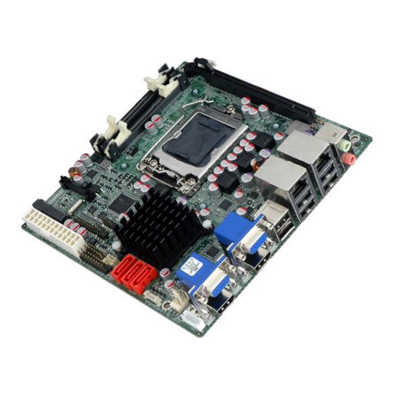
Mini-ITX SBC supports LGA1155 Intel® Core™ i7 /i5/ i3
/Pentium/ Celeron CPU, DDR3, dual HDMI / dual VGA, Dual
GbE, SATA 3Gb/s, HD Audio and RoHS
Quick Installation Guide
Package Contents
KINO-AH611 package includes the following items:
1 x KINO-AH611 Single Board Computer
3 x SATA Cable
1 x Dual RS-232 Cable
1 x I/O shielding
1 x Mini Jumper Pack
1 x Utility CD
1 x One Key recovery CD
1 x QIG (Quick Installation Guide)
KINO-AH611
Version 1.01
May. 22, 2012
©2006 Copyright by IEI Technology corp.
All rights reserved.
1
Advertisement

Subscribe to Our Youtube Channel
Related Manuals for IEI Technology KINO-AH611


Summary of Contents for IEI Technology KINO-AH611
- Page 1 GbE, SATA 3Gb/s, HD Audio and RoHS KINO-AH611 Quick Installation Guide Version 1.01 May. 22, 2012 Package Contents KINO-AH611 package includes the following items: 1 x KINO-AH611 Single Board Computer 3 x SATA Cable 1 x Dual RS-232 Cable ...
- Page 2 Specifications CPU: LGA1155 socket supports Intel® Core™ i7/ i5 /i3/ Pentium/ Celeron processor System Chipset: Intel® H61 BIOS: AMI UEFI BIOS System memory: Two 204-pin 1066/1333MHz Dual-channel DDR3 SDRAM SO-DIMM supported (system max. 16GB) Ethernet: Dual Realtek RTL8111E GbE Controllers with ASF2.0 support ...
- Page 3 Ordering Information KINO-AH611-R10: Mini-ITX SBC supports LGA1155 Intel® Core™ i7 /i5/ i3 /Pentium/ Celeron CPU, DDR3, dual HDMI / dual VGA, Dual GbE, SATA 3Gb/s, HD Audio and RoHS 19800-003100-200-RS: Dual-port USB cable with bracket 32102-000100-200-RS: SATA power cable ...
- Page 4 Jumpers setting LABEL FUNCTION J_CMOS1 CMOS state setting JATX_AT1 ATX or AT Mode Selection J_CMOS1: Clear CMOS Setup JATX_AT1 : ATX or AT Mode Selection PIN NO. DESCRIPTION PIN NO. DESCRIPTION Short 1-2 ATX Power(default) Keep CMOS Setup Short 2-3 AT Power Short 1-2 (default)
- Page 5 Table of Connectors LABEL FUNCTION SATA1~3 Serial ATA 2.0 Connector F_PANEL1 Front Panel connector JSPI1 SPI Flash Program Connector JSPI2 EC SPI Flash Program Connector TPM1 Trusted Platform Module connector COM1~2 Internal Serial 2*5 Pin-header DIO1 Digital I/O Connector CPU_FAN1 4-pin CPU FAN Connector SYS_FAN1 3-pin System FAN Connector...
- Page 6 SATA1~3: Serial ATA Connector PIN NO. DESCRIPTION PIN NO. DESCRIPTION F_PANEL1 : PWR & RST Buttons and Indicators panel DESCRIPTION DESCRIPTION ACPILED BEEP_PWR PWR_LED BUZZER 7 PWRBTN_SW#_C 8 PC_BEEP PWR_BTN IDELED+ EXTRST- HDD_LED RESET IDELED- TPM1:Trusted Platform Module connector PIN NO. DESCRIPTION PIN NO.
- Page 7 DIO1 : Digital Input / Output Connector PIN NO. DESCRIPTION PIN NO. DESCRIPTION Output 3 Output 2 Output 1 Output 0 Input 3 Input 2 Input 1 Input 0 CPU_FAN : CPU Fan Connector SYS_FAN1 : System Fan Connector PIN NO. DESCRIPTION PIN NO.
- Page 8 ATX12V1 : +12V MAIN POWER Connector ATX 12V1 PIN NO. DESCRIPTION PIN NO. DESCRIPTION +12V +12V JSPI1: Flash SPI ROM Connector PIN NO. DESCRIPTION SPI_VCC SPI_CS# SPI_MISO SPI_CLK SPI_MOSI KB_MS1: 6-pin Wafer Keyboard Connector PIN NO. DESCRIPTION VCC5_KBMS MSDATA MSCLK KBDATA KBCLK KBGND...
- Page 9 USB2: Internal USB Connectors PIN NO. DESCRIPTION PIN NO. DESCRIPTION DATA- DATA+ DATA+ DATA- HDMI1/2 : HDMI Connector DESCRIPTION DESCRIPTION HDMI_DATA2 HDMI_DATA2# HDMI_SCL HDMI_DATA1 HDMI_SDA HDMI_DATA1# HDMI_DATA0 HDMI_HPD HDMI_GND HDMI_DATA0# HDMI_GND HDMI_CLK HDMI_GND HDMI_GND HDMI_CLK# LANUSB1~LANUSB2 PIN NO. DESCRIPTION PIN NO. DESCRIPTION MDIA3- MDIA1+...
- Page 10 AUDIO_CV1 PIN NO. DESCRIPTION Line_out Connect this port to headphone or speaker Microphone Connect this port to microphone CN2: PCIe Mini Card Slot PIN NO. DESCRIPTION PIN NO. DESCRIPTION PCIE_WAKE# VCC3 1.5V CLKREQ# LFRAME# LAD3 CLK- LAD2 CLK+ LAD1 LAD0 PCIRST# VCC3 PCIRST#...
- Page 11 VGA1,VGA2: VGA 15-pin Female Connector DESCRIPTION DESCRIPTION GREEN BLUE VCC / NC DDC DAT HSYNC VSYNC DDCCLK USB1: External USB Connector PIN NO. DESCRIPTION PIN NO. DESCRIPTION VCC (+5V) VCC (+5V) DATA4- DATA5- DATA4+ DATA5+...
- Page 12 Board Layout: Jumper and Connector Locations...
Need help?
Do you have a question about the KINO-AH611 and is the answer not in the manual?
Questions and answers