Table of Contents
Advertisement
Quick Links
Advertisement
Table of Contents

Related Manuals for HBK MXFS


Summary of Contents for HBK MXFS
- Page 1 ENGLISH User Manual MXFS QuantumX BraggMETER Module...
- Page 2 Hottinger Brüel & Kjaer GmbH Im Tiefen See 45 64293 Darmstadt Germany Tel. +49 6151 803-0 Fax +49 6151 803-9100 info@hbkworld.com www.hbkworld.com HBK FiberSensing, S.A. Rua Vasconcelos Costa, 277 4470-640 Maia Portugal Tel. +351 229 613 010 Fax +351 229 613 020 info.fs@hbkworld.com www.hbkworld.com Mat.:...
-
Page 3: Table Of Contents
2.3.3.2 Nameplate MXFS DI .......... - Page 4 ..........Starting a project with MXFS .
- Page 5 ..........MXFS...
-
Page 6: Technical Details
TECHNICAL DETAILS General Information The MXFS is a module from the QuantumX family for measuring Fiber Bragg Grating (FBG) based sensors. It is based on the well-established BraggMETER technology from HBK FiberSensing, that employs a continuous swept laser scanning for measuring reflected Bragg peaks. -
Page 7: System Components
1-KAB239-2 Ethernet crossover cable 2 m Software MXFS is an open data acquisition system. It can be integrated into many operating, analy sis and automation software packages. Available for download are: MX Assistant and Common API: modern and free device assistants that support the module acquisition and data functions;... -
Page 8: Regulatory And Certification Considerations
FiberSensing to Amb3E. Laser Safety The MXFS Interrogator contains a laser in its core. A laser is a light source that can be dangerous to people exposed to it. Even low power lasers can be hazardous to a person's eyesight. The coherence and low divergence of laser light means that it can be focused by the eye into an extremely small spot on the retina, resulting in localized burning and permanent damage. -
Page 9: Symbols
2.2.2 Class 1 Laser The MXFS is a Class 1 laser product: ≪Any laser or laser system containing a laser that cannot emit laser radiation at levels that are known to cause eye or skin injury during nor mal operation.≫ It is safe under all conditions of normal use. No safety requirements are needed to use Class 1 laser devices. -
Page 10: Certification
This product has been designed to safely interrogate optical sensors in explosive atmospheres. It is therefore important to follow the instructions in this manual to ensure safe use. MXFS REGULATORY AND CERTIFICATION CONSIDERATIONS... -
Page 11: Laws And Directives
This product complies with EN 45545-2:2016 and EN 45545-2:2020 for the hazard levels HL1, HL2, and HL3. When installing the MXFS without the X frame, no combustible mass has to be taken into account according to the grouping rules in section 4.3 of DIN EN 45545-2. -
Page 12: Marking Of Pollutant Emission Limit Values (For Deliveries To China)
Emphasis Italics are used to emphasize and highlight text and See … identify references to sections, diagrams, or external documents and files. " This marking indicates an action in a procedure. MXFS REGULATORY AND CERTIFICATION CONSIDERATIONS... -
Page 13: Operation
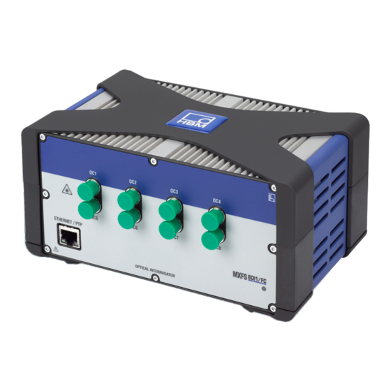
OPERATION Connectors Fig. 3.1 Front and back view of the MXFS Optical Connectors (FC/APC); Ethernet Connectors; STATUS LED; Power connector; Firewire connectors; Backplane connector. Setting up 3.2.1 Power supply Connect the modules to a DC voltage. The power consumption and accepted supply volt... -
Page 14: Connection And Syncronization To Pc And Other Modules
The QuantumX MXFS module is designed to synchronize with other QuantumX/SomatXR modules of the same family, allowing for simultaneous data acquisition. This synchro nization can be achieved by connecting the modules through FireWire or Ethernet inter faces. Alternatively, the MXFS module can function as a gateway, collecting synchronized MXFS OPERATION... -
Page 15: Single Ethernet Connection
FireWire and transmitting it to the PC using an Ethernet interface cable. It is essential to ensure proper synchronization between the MXFS mod ule and other devices to maintain accurate timing. For more detailed information on syn... -
Page 16: Multiple Ethernet Connection With Ptp Synchronization
Ha-VIS FTS 3100-PTP from Harting; Stratix 5400 from Rockwell. PTP Grandmaster Clock examples: LANTIME M600 from Meinberg; OTMC 100 from Omicron. With the star structure displayed here, measurement data from other modules is not lost if the Ethernet cable is broken! MXFS OPERATION... -
Page 17: Multiple Ethernet Connection And Firewire Synchronization
Advantage of this connection structure: The other modules remain active if the Ethernet cable is broken. 3.2.2.4 Other possible connections There are several other possibilities of connection between MXFS modules or MXFS and other QuantumX modules: Connection of a single module via FireWire; Connection of several modules via FireWire;... -
Page 18: Communication Settings To The Pc
PC / notebook 172.21.108.51 255.255.248.0 Module after 172.21.108.1 255.255.248.0 The first three digit groups of the PC and module IP addresses should be the same. The subnet mask address digit groups must be identical in the module and PC! MXFS OPERATION... - Page 19 TCP/IP the Alternative Configuration in the TCP/IP proper ties (fixed IP address and subnet mask, user-defined)! " On the control panel choose Network Connections. " Select the LAN connection. The window displayed in Fig. 3.7 will appear. Click on Properties. MXFS OPERATION...
- Page 20 Fig. 3.7 Network properties MXFS OPERATION...
- Page 21 " Select the Internet Protocol (TCP/IP) and click on the Properties button (Fig. 3.8). Fig. 3.8 TCP/IPv4 MXFS OPERATION...
- Page 22 Set the IP address and the Subnet mask (Fig. 3.9). Fig. 3.9 IP and Subnet " Press OK. Integrating modules in an Ethernet network " Activate the DHCP checkbox and click on OK. The following confimation window then appears: Fig. 3.10 DHCP confirmation window MXFS OPERATION...
-
Page 23: Mounting
MXFS Positioning When installing the MXFS interrogator, please exercise caution regarding its placement. The MXFS interrogator does not have active ventilation, so it is important to choose a well-ventilated location to prevent overheating. The MXFS interrogator can be positioned in any orientation without impacting its func... - Page 24 Fig. 3.11 MXFS with case protection MXFS housing; Case protection; Top side cover; Bottom side cover. Models can be secured together via a clip-on connection (order number 1-CASECLIP). " Remove the X frame case protection (number 2 in Fig 1) using a 2.5 hexagonal screwdriver (number 1 in Fig 2).
- Page 25 The mounting of the housing clips shown in the following pictures must be implemented on both sides of the housing. Only one CASECLIP set is needed for both sides. Fig. 3.13 MXFS without case protection " Remove the bottom side cover (number 4 in Fig. 3.11) using a 2.5 hexagonal screwdriver.
- Page 26 Fig. 3.15 Mounting the CASECLIP Fig. 3.16 MXFS with CASECLIP on " Optionally, reattach the X frame protection. The interrogator can now be clipped to another module or to a CASEFIT (order number 1-CASEFIT) as any other QuantumX Module.
-
Page 27: Status Indicators
Status indicators Fig. 3.17 MXFS front view The MXFS presents a system Led on the front panel that lightens with different colors: System LED Green Error-free operation Orange System is not ready, boot procedure running - Optical Module is warming up... -
Page 28: Ventilation
Factory reset It is possible to reset the MXFS module to its factory settings which will delete the config uration in use by the device: Deactivates all channels;... -
Page 29: Connecting To Optical Sensors
Concepts and definitions 3.7.1.1 Connectors The MXFS has 8 FC/APC optical connectors located on its front panel (see Fig. 3.1). The device is ready to receive several Fiber Bragg Grating (FBG) sensors connected in series on the same optical fiber. - Page 30 To visualize the spectrum and/or manually adjust the defined ranges use the provided catman®Easy software. Information The minimum distance between ranges is of 0.5 nm. Smaller distances between ranges limits is considered an overlap. MXFS OPERATION...
-
Page 31: Wavelength
The reference wavelength is, for non calibrated sensors, the zero value of the measure ment. For calibrated sensors, the reference wavelength should be defined as stated on their calibration sheets. Measured Wavelength Wavelength value of the FBG peak at each acquired sample. MXFS OPERATION... -
Page 32: Power
3.7.1.4 Power The power value corresponds to the optical power reflected by the fiber Bragg grating at peak wavelength. Fig. 3.21 Power Power axis in dBm; FBG reflected spectrum; FBG peak; Power value in dBm. MXFS OPERATION... -
Page 33: Dynamic Range
FBG peak inside each con figurable band. MXFS DI considers a fixed threshold value of 3 dB, easing the configuration of the device (Fig. 3.23). Every wavelength value is calculated considering the area of the FBG peak above half its power. - Page 34 Summarily, the increased robustness provided is especially suited to overcome the limi tations found in the conventional methods where low and high reflectivity FBGs coexist and signal losses are often a problem. SPD therefore improves the stability and accuracy MXFS OPERATION...
-
Page 35: Signals
Measured wavelength within the channel (λ) in nm; Wavelength variation within the channel, in nm. If the peak falls out of the defined bands for the channel, an overflow value is presented. The wavelength variation relates to the signals via conversion factors. MXFS OPERATION... - Page 36 Temperature Converted wavelength (λ * λ (λ * λ (λ * λ ) ) S variation into tempera ture based on calibra tion coefficients (S and S ). Conversion for mula is a second order polynomial. MXFS OPERATION...
- Page 37 MXFS signals have a one to one relationship with the FBG peak. This means that complex sensors that use more than one FBG, or computations performed using values from two FBG are not possible to be performed within the device.
-
Page 38: Acquisition Rate
Acquisition rate 3.8.1 Speed mode MXFS DI operates with two different speed modes that correspond to two sweeping laser speeds: MXFS DI Low speed mode: 100 S/s High speed mode: 2000 S/s Information Changing the speed mode will restart the device. - Page 39 (3·10 m/s). This means that for MXFS, the shift in wavelength is given by a function of the distance and the acquisition rate defined on the interrogator: Wavelength shift due to sweeping laser speed in MXFS Δλ...
- Page 40 (1.446 for standard SMF28 fiber); FullRange is the length of the range of measured wavelengths (102 nm for BraggMETER interrogators); For MXFS distance computation can be done by using the two speed modes. Distance calculation using the two speed modes * λ...
-
Page 41: Filters
In catman use a computational channel to get the distance correction. 3.8.3 Filters MXFS supports low-pass filtering, as any other QuantumX Module. Available filters are Bessel, Butterworth, linear phase. Please check chapter 4.2.1.2 “Sampling rate and filters”, page 49 for more details. - Page 42 To clean an optical interrogator adapter, use an appropriate cotton swab (there are sev eral cleaning swabs in the market frequently used for telecom fibers) embedded in iso propyl alcohol. Insert it in the optical adapter as in Fig. 3.28 and rotate the swab always in the same direction. MXFS OPERATION...
-
Page 43: Broken Connector
3.9.3 Transitory measurement overflows During its operation, MXFS may need to readjust some internal parameters. During this action, the unit will temporarily return an overflow value for all sensors in all channels. The probability of this event to happen increases for large temperature variations and higher sampling rates. - Page 44 Further details on alarms and waiting times in catman can be found on catman operating manual A05566 (available on the website) - pages 214 and 215. MXFS OPERATION...
-
Page 45: Catman Software
CATMAN SOFTWARE MXFS includes one license for catman Easy software which should be used to configure the device. MXFS is compatible with catman versions 5.4.1 or above. Starting a project with MXFS " Launch catman software. " On the start menu select a QuantumX/SomatXR the device type. -
Page 46: Synchronization
Connectivity " Start a new measurement project. Information MXFS gateway functionality is not supported in catman. Please switch it off with MX Assistant before using MXFS with catman. 4.1.1 Synchronization Different synchronization methods for MXFS are available. Please refer to catman user manual (A05566) for more details on how to setup these. -
Page 47: Catman Project For Mxfs
Catman project for MXFS When a new project is started with an MXFS device, catman starts by populating the channel list with all channels from MXFS. Fig. 4.3 DAQ channels Channels that have defined bands - ranges of wavelength - on the device are seen as active and non defined channels are seen as inactive. -
Page 48: Sample Rates
Fig. 4.4 Hiding inactive channels 4.2.1 Sample rates 4.2.1.1 Acquisition rate MXFS operates with two different speed modes that correspond to two sweeping laser speeds, which can be set in catman: MXFS DI Low speed mode: 100 S/s High speed mode:... -
Page 49: Sampling Rate And Filters
Fig. 4.5 Acquisition rate " Right click over any MXFS channels’ sampling rate column. " Select High Speed mode on or off. Information Changing the speed mode will restart the device. Important In sweeping laser based Optical Interrogators the length of cabling between the inter... - Page 50 MXFS DI Low speed mode (100 S/s) Filter cut-off Available sample rates frequency (Hz) MXFS DI High speed mode (2000 S/s) Filter Available sample rates cut-off frequency (Hz) 10 20 50 100 200 500 1000 2000 10 20 50 100 200 500 1000 2000...
-
Page 51: Configuring Ranges Of Wavelength
Configure ranges button Important All changes performed on the configure ranges interface will only become active after pressing the Apply button. If you exit without applying the changes these will not be visible on the device not the channel list. MXFS OPERATION... - Page 52 Spectrum is displayed as measured on the moment the configure ranges window is called. " To update the optical spectrum press the Update spectrum button (Fig. 4.8). " For a continuous update check the Live update tick (Fig. 4.8). Fig. 4.8 Update Spectrum MXFS OPERATION...
-
Page 53: Automatically Define Bands For The Detected Peaks
(number in Fig. 4.9). Fig. 4.9 Automatic band definition On the bottom of the window " Define band width, in nm. The band width corresponds to the full wavelength range of the channels. " Press Create. MXFS OPERATION... - Page 54 Writing on the table the minimum band value, maximum band value and reference wavelength - number in Fig. 4.11 . " Or adjusting the minimum band value, maximum band value and reference wavelength with the scroll bars at the bottom - number in Fig. 4.11. MXFS OPERATION...
-
Page 55: Individually Define Bands By Hand
Bands can be created by editing their information on the table. To select a channel: " Select the line on the table (line will be highlighted in blue on the table and the band, if already defined, will be highlighted in green on the graph). MXFS OPERATION... - Page 56 Create band in this place. This will define a band centered at the clicked pixel, with the defined settings for the automatic detection of bands, for the selected channel. Fig. 4.13 Editing or creating bands MXFS OPERATION...
-
Page 57: Sensors On The Device
There are different types of sensors that can be configured into the device (for more details please refer to section 3.7.1.7 “Signals”, page 35). " Double-click on the Sensor/Function column for changing or configuring sensors into the device. MXFS OPERATION... -
Page 58: Sensors On The Software
4.2.4 Sensors on the software Optical sensors for MXFS are available on catman database under General Sensors > MXFS. Fig. 4.15 Optical sensors on sensors database MXFS OPERATION... -
Page 59: Wavelength
Fig. 4.16 Wavelength Absolute and Wavelength Relative sensor types Wavelength Relative is the “raw” value out of MXFS device. That means that it is the wavelength variation of the FBG peak in that channel. No calculation is performed on the signal, as all is processed inside the device (see section 3.7.1.7 “Signals”, page 35 for... - Page 60 When using a temperature channel to compensate for the effect of temperature on the strain measurement, it must be ensured that the changes in temperature felt by the two sensors is the same. The selected channel for temperature compensation with this method must be configured as a temperature sensor. MXFS OPERATION...
- Page 61 They can be filled by hand or automatically defined by an actual measurement using the Measure button. λ * λ Strain with compensation using a * (CTE ) TCS)(T * T k @ λ temperature sensor MXFS OPERATION...
- Page 62 This value should be measured after installation. It can be filled by hand or automatically defined by an actual measurement using the Measure button. λ * λ * λ Strain with compensation using a compen λ sation FBG k.λ k.λ MXFS OPERATION...
-
Page 63: Temperature
4.2.4.3 Temperature HBK FiberSensing temperature sensors are delivered with a calibration sheet. They show a polynomial behavior with temperature. Fig. 4.20 Temperature sensor The S coefficients are the values given on the sensors’ documentation. Important For sensors with a second order calibration polynomial ensure that S is set as zero. -
Page 64: Acceleration
4.2.4.4 Acceleration HBK FiberSensing acceleration sensors are delivered with a calibration sheet. They show a linear behavior with acceleration. Fig. 4.21 Acceleration sensor The calibration coefficient (S) is the value given on the sensors’ documentation. The reference wavelength of the FBG acceleration senor (λ... -
Page 65: Generic Polynomial
Catman allows the creation of computational channels that can replace the adaptation performed on top of the actual device channel, hence allow the recording of raw data, and create more complex computations, for example involving several channels measure ments. MXFS OPERATION... - Page 66 Dual FBG sensor computation Many FBG based sensors have 2 gratings for a temperature corrected measurement. Tilt sensors, displacement sensors, load sensors from HBK standard sensor portfolio are examples of these. For converting wavelength measurements into engineering values in catman® a computational channel must be used.
- Page 67 By using this interface, catman will create as many com putational channels as selected. Information Available optical rosettes are available as 60º/120º type and the three measurement direc tions are marked as a, b or c, matching catman’s menu. MXFS OPERATION...
-
Page 68: Zero Balance
" To zero one or more sensors, select the desired lines and press the Zero balance but ton on the top ribbon. Fig. 4.26 Zero Balance MXFS OPERATION... -
Page 69: Reset Reference Wavelength
In a similar way to the Zero balance, it is also possible to reset the reference wavelength to the value being measured at the moment. " Right click on the line to reset and select Reset reference wavelength option (number in Fig. 4.27). MXFS OPERATION... -
Page 70: Reset The Device
Always take extra care upon resetting ref erence wavelength values. Reset the device The MXFS interrogator can be reset to its factory settings via catman software. " Right click over the device name and select Device Reset. - Page 71 Reset channel names will: change all channel names to its default (<Device Name>_CH_<Connector #>-<Chan nel #>, e.g. MXFS8_CH_2-13 for channel 13, in connector 2 of the device MXFS8). The option activate TEDS is not applicable to MXFS. MXFS OPERATION...
- Page 72 HBK - Hottinger Brüel & Kjaer www.hbkworld.com info@hbkworld.com...
Need help?
Do you have a question about the MXFS and is the answer not in the manual?
Questions and answers