Table of Contents
Advertisement
Available languages
Available languages
Quick Links
Advertisement
Chapters
Table of Contents

Related Manuals for HBK DSE


Summary of Contents for HBK DSE
- Page 1 ENGLISH DEUTSCH Operating Manual Bedienungsanleitung...
- Page 2 Hottinger Brüel & Kjaer GmbH Im Tiefen See 45 D-64293 Darmstadt Tel. +49 6151 803-0 Fax +49 6151 803-9100 info@hbkworld.com www.hbkworld.com Mat.: DVS: A05529 01 X00 02 04.2022 E Hottinger Brüel & Kjaer GmbH Subject to modifications. All product descriptions are for general information only.
- Page 3 ENGLISH DEUTSCH Operating Manual...
-
Page 4: Table Of Contents
......... . Connecting DSE via TCP/IP . - Page 5 8.3.1 DSE general ............
-
Page 6: Safety Instructions
Intended use The Digital Sensor Electronics (DSE) is to be used exclusively for measurement tasks and directly related control tasks (automation systems). Use for any purpose other than the above is deemed improper use. In the interests of safety, the device should only be operated as described in the operating manual. - Page 7 As a commissioning or service engineer, you have successfully completed training on the repair of automation plants. Moreover, you are authorized to start up, ground and label circuits and equipment in accordance with safety engineering standards. Residual dangers This is a state-of-the-art device that is safe to operate. The performance and scope of supply of the device cover only a small proportion of test and measuring equipment however.
-
Page 8: Markings Used
MARKINGS USED Markings used in this document Important instructions for your safety are highlighted. Following these instructions is essential in order to prevent accidents and damage to property. Icon Meaning This marking draws your attention to a situation in Notice which failure to comply with safety requirements could lead to property damage. -
Page 9: Symbols On The Device
Symbols on the device CE mark With the CE mark, the manufacturer guarantees that the product complies with the requirements of the relevant EC directives (the Declaration of Conformity can be found on the HBM website (www.hbm.com) under HBMdoc). Statutory waste disposal marking In accordance with national and local environmental protection and material recovery and recycling regulations, old devices that can no longer be used must be disposed of separately and not... -
Page 10: Overview
Fig. 3.1 Function blocks and electrical isolation of the DSE You can control the DSE via the PROFINET interface and communicate directly with your control system, and also connect it to the Ethernet port on your PC. Use the integrated web user interface for configuration and to view the current measurement values. -
Page 11: Dimensions
Dimensions Ø6.6 80±0.4 Dimensions in mm Fig. 3.2 Dimensions of the DSE Information You will find 3D files to support your design process at https://www.hbm.com/DSE OVERVIEW... -
Page 12: Accessories
Accessories 1-KABxxx 1-KABxxx 1-DSE-A02 1-KABxxx 1-KABxxx 1-DSE-A01 Fig. 3.3 Accessories For EHEDG-compliant mounting, you must use EHEDG-compliant plugs and cables, and the appropriate screw connections. You can order the following EHEDG-compliant accessories from https://www.hbm.com/shop Designation Description Ordering number Sensor Connection cable with M12 socket on both ends 1-KAB186-0.3... - Page 13 Plugs and cables for applications that do not require EHEDG compliance: Designation Description Ordering number Sensor Cable socket M12, 8-pin, with straight cable outlet, 1-CON-S3003 connection A-coded, IP67 Cable socket M12, 8-pin, with angled (90°) cable 1-CON-S3004 outlet, A-coded, IP67 Connection cable with M12 socket on both ends, 1-KAB189-0.3 8-pin, 0.3 m long, A-coded, IP67...
-
Page 14: Mounting
Fig. 4.1 Possible mounting positions You can mount the DSE-HIE in almost any orientation on the x and y axes. In both typical (0°) and overhead (180°) variants, you can mount the DSE freely rotated through 360° around its own axis (illustration on left). - Page 15 Fig. 4.2 EHEDG-compliant mounting Two fixing holes, 80 mm apart, are provided for mounting. You can mount the DSE in two different ways: with a blind hole or with a through-hole. For mounting through a blind hole we recommend hygienic mounting set 1-DSE-A02.
-
Page 16: Installation
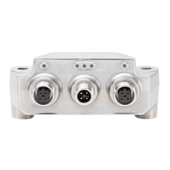
The DSE has a total of four M12 connections. Important The DSE only complies with the IP69k equipment protection level when all connections are screwed in place. If you use only one Ethernet port, protect the unused one against external harm with a screw-fit cap. - Page 17 X1, sensor connection The DSE has an 8-pin M12 plug (A-coded) for connecting the sensor. This is located on the front of the DSE, and is labeled X1 ([1] in Fig. 5.1). The pin assignment is shown in Fig. 5.2.
- Page 18 Connect the cable shields extensively to the connector housing. X3, power supply connection The DSE has an 4-pin M12 plug (T-coded) for connecting the power supply. This is located in the middle on the back, and is labeled X3 ([4] in Fig. 5.1). Note that the...
-
Page 19: Shielding And Grounding Design
When using a shielded cable, the shield is routed through the connector housing. This shields your system. Grounding If you need to ground the DSE, use one of the two fastening points. When installing the ground, make sure that it is in compliance with EHEDG where required. INSTALLATION... -
Page 20: Status Leds
Important In the event of voltage surges on the DC system (as per 61000-4-5 and EN 45501) the DSE module may restart, causing it to fail sporadically. The module's downtime is usually about 1 second. The time taken to reconnect to a PROFINET master depends on the connected network. -
Page 21: Multiple Dses In Operation
Star topology If you want to operate the DSE as shown in Fig. 5.7 on the left, in a system with star topology, you will need a network switch. Use this to interconnect all the DSEs. Then connect either the automation controller or your PC to the switch. - Page 22 Fig. 5.7 DSE in star topology (left) and ring topology (right) INSTALLATION...
-
Page 23: Connecting Dse Via Tcp/Ip
Establishing a network connection to a PC Cabling To set up the DSE via the web interface (section 7, Web interface, page 40), you must establish a connection between the DSE and your computer. You have two options for this: 1. - Page 24 (the xxxx stands for the version number). Assign a separate static IP address for each connected DSE. The subnet mask is normally identical for all devices. You can change the IP address and subnet mask again later if necessary via the web interface or using a DCP program.
- Page 25 Enter the IP address, the subnet mask, and the default gateway where appropriate. If in doubt, ask your network administrator for the correct values. Uncheck the Store settings temporary box. Click on OK Close the program. The DSE now has a new IP address. CONNECTING DSE VIA TCP/IP...
- Page 26 DHCP address assignment. You can then assign the PC a static IP address in the same address range as the DSE. If you are using the DSE on a network, make sure that the IP address range you are using is compliant with your IT's specifications.
-
Page 27: Connecting By Profinet
This section describes the use of the PROFINET protocol for communicating between a DSE and a Siemens PLC. The example shows the settings for the project in the TIA portal software, and how to transfer individual values. The example assumes that the DSE has already been configured via the web browser, you have downloaded the GSD file either from the device or from the HBM website, and the DSE and PLC are interconnected. - Page 28 Fig. 6.2 Adding a new device Add your PLC in the dialog that follows. Fig. 6.3 Adding a PLC CONNECTING DSE VIA TCP/IP...
- Page 29 Install the file. Fig. 6.5 Installing a general station description file Now locate the DSE in the hardware catalog. Drag and drop the DSE next to the PLC. Connect the PLC's PROFINET inputs (green) to the DSE. CONNECTING DSE VIA TCP/IP...
- Page 30 Fig. 6.6 Selecting the DSE and connecting to a PLC Click on the green dot on the PLC. On the General tab select Ethernet addresses. Enter the PLC's Ethernet address (here 192.168.178.50). Fig. 6.7 Entering the PLC's Ethernet address CONNECTING DSE VIA TCP/IP...
- Page 31 DSE a station name if you want. Fig. 6.8 Entering the DSE's Ethernet address and station name Switch to the DSE device view, by double-clicking on the device for example. From the Hardware catalog drag and drop the Measurement (float) module into the Device overview.
- Page 32 Open the Devices tab, PLC tags group and choose Add new tag table. Fig. 6.10 Adding a new tag table Add the two values as variables with the start addresses from the list. The length is determined by the data type (REAL or F32). CONNECTING DSE VIA TCP/IP...
- Page 33 To load the program into the PLC, click on the icon in Fig. 6.12. In the dialog that follows, select the PLC and choose Load (Fig. 6.13). Fig. 6.12 Loading a program into the PLC Fig. 6.13 Loading a program into the PLC CONNECTING DSE VIA TCP/IP...
- Page 34 Confirm the preview with Load. Fig. 6.14 Program preview Load the program and click Finish to run it. Fig. 6.15 Starting the program CONNECTING DSE VIA TCP/IP...
-
Page 35: Connecting By Ethercat
This section describes the use of the EtherCAT protocol for communicating between a DSE and a PLC. The example shows the settings for the TwinCAT software (version 2.11), and how to access values. The example assumes that the DSE has already been configured via the web browser, you have switched the interface to EtherCAT (see also section 7.9.2, page 71), and the EtherCAT master and the DSE are interconnected. - Page 36 Fig. 6.18 Scanning for connected boxes Add the DSE. Double-click on the DSE you just added. On the Process Data tab, click on Load PDO info from device. CONNECTING DSE VIA TCP/IP...
- Page 37 Fig. 6.19 Loading PDO info In the Sync Manager area select the inputs and outputs, and in the PDO Assignment area select the signals to be transmitted. CONNECTING DSE VIA TCP/IP...
- Page 38 Fig. 6.20 Selecting signals Use the context menu (right mouse button) of Inputs under Task2 to create a new variable (Fig. 6.21) – here a float variable for measured values (Var35). CONNECTING DSE VIA TCP/IP...
- Page 39 Fig. 6.21 Creating a variable for measured values Assign the gross measured value of the DSE to this variable (Var35): Under Box1 in the Measurement REAL group, double-click on Gross value. Fig. 6.22 Assigning a signal to the variable CONNECTING DSE VIA TCP/IP...
- Page 40 Apply the configuration, and start the PLC's run mode. Fig. 6.23 Starting the program You now have access to all channels. The gross measurement value is transferred in Var35. CONNECTING DSE VIA TCP/IP...
- Page 41 Fig. 6.24 DSE signals CONNECTING DSE VIA TCP/IP...
-
Page 42: Web Interface
Return ( This will load the DSE user interface. The first time you run it, it can take up to eight seconds until the interface is fully loaded and displayed, due to parallel transmission via Industrial Ethernet. -
Page 43: Home
Use the navigation to select one of the menus: Home Device Amplifier Autozero Filter Application Mode Fieldbus Parameter Sets Device Storage Status area The status area shows you the current operating status of the DSE, and displays all the information relevant to the weighing process. WEB INTERFACE... - Page 44 Parameter Sets menu. Processor Indicates the load on the processor in percent. load Heartbeat The pulsing of the icon indicates that communication has been established with the DSE. Status Corresponds to the system LED of the DSE. WEB INTERFACE...
- Page 45 Icon Status Explanation Find device Click on the icon and the System LED on the DSE you are using will flash red/green. Help Opens the online help. The relevant help topic opens up specific to the menu item. Language Use this icon to toggle the display language between German and English.
- Page 46 Main window The content of the main window depends on the menu item selected in the navigation area. The content from the Home view is shown with most menus, so you can always see the current measured value. With some menus, only the graph on the right is shown in the Home display, so that you can record and analyze measurements.
- Page 47 If the icon is not shown, there are no changes. As you can set the DSE not only by the user interface but also via the fieldbus objects, you will also find the corresponding objects, with their index, below. You will find a detailed list of all objects in section 8 “Industrial Ethernet”, page 73.
- Page 48 The DSE home screen displays the current measurement values (gross and net signal) numerically and graphically. On the top line, the status bar shows you the current operating status of the DSE, and displays all the information relevant to the weighing process.
- Page 49 This menu displays information about the device such as its serial number and firmware version. You might need this information if you have problems operating the DSE and are in contact with HBM Technical Support (see section 11, page 97). You can also see a number of values from the device: various temperatures, the humidity in the housing, and the current supply voltage.
- Page 50 30 seconds in total. During this time, the LEDs on the device flash alternately. Amplifier Use this menu item to define some general settings for measuring, and to calibrate the measurement chain. You have two options for calibrating the DSE: Automatic or Manual. WEB INTERFACE...
- Page 51 If you select a parameter set afterward, the settings for that parameter set will be loaded, overwriting your own. Automatic calibration The DSE can perform the adjustment by measuring with an exact weight (test or calibration weight): In the Calibration area click on Automatic.
- Page 52 Fig. 7.7 Automatic calibration Important The results of the adjustment are initially only stored temporarily. You can save them permanently in the device, like all value changes, in the Parameter Sets menu. Information Using PROFINET, you can perform the adjustment via the following objects: Name Index Subindex...
- Page 53 Manual adjustment Perform a manual adjustment as follows: In the Calibration area click on Manual. Enter the desired Measuring unit and Rated capacity of your load cell. Enter the values for the zero load at x1: Value unloaded in mV/V and for rated capacity at x2: Value at rated capacity in mV/V.
- Page 54 General settings Fig. 7.9 Amplifier menu The following settings are available: Decimal Point: Select the desired number of decimal places. The maximum number of digits before and after the decimal place that can be displayed is 8. If your selection exceeds this value, it will be discarded.
- Page 55 calculated as (1 / (10^number of decimal places)) * resolution, so corresponds to the "smallest" change (digit increment) displayed by the scale. For three decimal places and a resolution of 0.002, the result is 2/s. The value of d is also displayed on the second line under Weighing range in brackets (e = ).
- Page 56 You do not yet see the values currently being measured while measurement is in progress. The raw measurement data is displayed in full graphically only after the measurement is stopped. Only values measured after connecting to the device are displayed, as the values are not stored in the DSE. WEB INTERFACE...
- Page 57 Graphical representation Filter settings Measured value position mark Fig. 7.10 Filter menu Position markers There are two position markers at the left and right margins that you can drag over the measurement values using your mouse. The exact measurement values and the difference between the two positions are displayed directly below the graph.
- Page 58 Fig. 7.11 Filter menu, Filter area, with display of valid settings in event of input error You can zoom in and out with returns to the original view. Hold down the left mouse button to move the displayed area. opens a menu with various options: You can show or hide individual curves, see the filter's reaction to a step response, or activate the Y-zoom to enlarge the area between the position markers in the y-direction as well by clicking If the zoom level is sufficient, the individual measurement values will be shown on the...
-
Page 59: Notes On The Filters
Stages 1 and 2 cannot be removed, but you can disable them by not selecting a filter type. When you have set the filters as you need, click on APPLY CHANGES to transfer the values to the DSE. Important The settings are initially saved only temporarily. You can save them permanently in the device, like all value changes, in the Parameter Sets menu. -
Page 60: Notes On Typical Applications
Comb filters The comb filter eliminates both the selected frequency and its odd multiples (3rd, 5th, 7th, ... multiples of the fundamental) in the measurement signal. This filter type has a faster transient response than a moving average, and is best suited for interference signals with low harmonic content. - Page 61 Choose whether you want to implement a Multi-Range or Multi-Interval application. Then enter the values for the respective limits. Leave the value at 0 to avoid using the second limit. Fig. 7.12 Application Mode menu Information The display resolution of a stage is determined automatically depending on the resolu tion you initially selected.
-
Page 62: Checkweigher
Only values measured after connecting to the device are displayed, however, as the values are not stored in the DSE. The cursors in the graphic WEB INTERFACE... - Page 63 Simulation field. All changes are initially only included in the simulation and the graphs. When you have set ALL as you need, click on APPLY CHANGES to transfer the values to the DSE. Important The settings are initially saved only temporarily.
- Page 64 Trigger level: Starting at this level all times are taken into account, for example the settling time, and the measurement sequence begins. Settling time: The setting should be long enough so that the measured values are already as stable as possible. Measurement time: Define how long the measurement should or can continue before the product to be weighed leaves the belt.
- Page 65 Correction factor: You can use this function to make a correction between the static adjustment of the scale and the dynamic result. Each valid trigger result is multiplied by the correction factor. Start with post-trigger and external signal Select Pre-Trigger as the Trigger mode. This mode requires an external trigger signal received, for example, before the sample leaves the scale.
-
Page 66: Filler
values that are within the tolerance before the end of the post-trigger delay will be included in addition to the measurement time. Correction factor: You can use this function to make a correction between the static adjustment of the scale and the dynamic result. Each valid trigger result is multiplied by the correction factor. - Page 67 The statistics show the average values over the last 20 operations. Only values measured after connecting to the device are displayed, however, as the values are not stored in the DSE. General Target weight: This entry is required, otherwise you will not be able to start a process.
- Page 68 The coarse and fine flows are always activated separately (never simultaneously). In the coarse flow phase, only coarse flow is active. In the fine flow phase, only fine flow is active. Coarse flow is always activated during opening. It is active from the start of the filling process to the end.
- Page 69 Target weight Fine flow pre-act Fine flow cutoff point Coarse flow pre-act Coarse flow cutoff point Fig. 7.18 Definition of cutoff point and pre-act The coarse flow cutoff point must not be higher than the fine flow cutoff point. If you do not need coarse flow, set the pre-act to 0, then only the fine flow will be used.
- Page 70 Validation Residual flow time: The time for the residual flow (in-flight time) starts after the fine flow cutoff point is reached. The amount of material that has still to flow into the container after fine flow is deactivated is recorded during this time. This amount of material should be small, and as equal as possible for each filling process.
-
Page 71: Fieldbus
Coarse and fine flow rate: Enter the values for your process here so that the simulated curve is as close as possible to reality. Fieldbus ® As of firmware version 2.0, the DSE has two fieldbus systems: PROFINET ®1) EtherCAT . The connection via fieldbus is independent of the Ethernet connection. Both can run in parallel. - Page 72 For the Microsoft Windows operating system you can download an openAPI and executable examples from the HBM website: https://www.hbm.com/DSE . Even with the API, you can only make one connection to the device in total. The API uses the same Jet interface as when accessing by web browser.
-
Page 73: Ethernet And Profinet
An alternative is to use an Ethernet switch port, such as the Beckhoff EL6601, in the PLC. This will allow you to access the DSE via EtherCAT and via your browser. Click on SWITCH FIELDBUS to enable EtherCAT from your browser. -
Page 74: Device Storage
Under this menu item you can use SAVE to export all parameter sets, and transfer them to a different DSE for example. The parameter sets are compressed into a ZIP archive for the purpose. Depending on the browser and its settings, when you perform a download, a window appears to select a path and filename or the file is saved without a prompt in the download directory. -
Page 75: Industrial Ethernet
INDUSTRIAL ETHERNET ®1) The latest version of the DSE supports the PROFINET RT, PROFINET IRT and EtherCAT ® protocols. You can switch the fieldbus type in the device from PROFINET to EtherCAT via the ClipX web server for example. A maximum of one network connection (Ethernet or fieldbus) is possible. -
Page 76: Profinet Modules For Cyclic Data Traffic
PROFINET modules for cyclic data traffic Module Type R/W Format Explanation Byte Gross value Gross value. Net value Net value. Zero value The offset resulting from zeroing the gross value. Measure Tare value The offset resulting from taring ment the net value. Can be set by the (Integer) controller (preset tare). - Page 77 Module Type Format Explanation Byte Weighing Status as per CiA 461-3 object Status status 0x6012/01. 0x6012 Alarms Alarm Events as per CiA 461-3 object 0x6018 0x6018/01. OD Index Object read - Index. OD Subindex Object read - Subindex. Error code If Index and Subindex match the request, and the error code is Object...
- Page 78 Module Type Format Explanation Byte Filling result Filling result. Filling result Filling result status. status Filling count Number of filling results. Commands Bit 0: Start filling (Input flags Bit 1: Abort filling filler) Bit 2: Clear results Filling IDLE: 0 process START_DELAY: 1 status...
- Page 79 Module Type Format Explanation Byte Mean value Mean value of filling results. Standard Standard deviation of filling deviation results. Total weight Total weight of filling results. Current Current filling time. Filler dosing time extended Current Current coarse flow filling time. coarse flow time Current fine...
- Page 80 Module Type Format Explanation Byte Mean value Mean value of weighing results check weigher Standard Standard deviation of weighing deviation results check weigher Check Minimum Minimum weighing result weigher value check extended weigher Maximum Maximum weighing result value check weigher Result sam...
- Page 81 Command Response Function [String] [U32] idle 0x656c6469 Response to idle command. ok__ 0x5f5f6b6f Command was executed successfully. ongo 0x6f676e6f The procedure was started and is still running, e.g. after calz. __E1 0x31455f5f Error 1. __E2 0x32455f5f Error 2. __E3 0x33455f5f Error 3 –...
-
Page 82: Object Directory
Follow the same procedure to write a value to the object from the controller. To do this, send a write command from the controller to the DSE’s “Object Dictionary Write” module, which might look like this based on the example of object 0x6013 (number of decimal... -
Page 83: Dse General
As explained in the above example, you can then read back whether the value was applied correctly. The following objects are in the DSE's object directory. For the sake of clarity, they are divided into DSE-specific and CiA461-compliant objects. 8.3.1... - Page 84 Explanation Comments 3002 RW Simple scale command Bit 0: Tare Bit 1: Show gross Bit 2: Zero Tare sets to net display. 3002 Simple scale status Bit 0: Tare OK Bit 1: Gross is displayed Bit 2: Zero OK 301a Net output weight 3113 RW Scale maximum capacity...
- Page 85 Explanation Comments 3323 RW Comb filter 3 frequency in 1000 … 100000; default: 20000 3324 RW Comb filter 4 frequency in 1000 … 100000; default: 20000 3331 RW Linear moving average filter 1 1000 … 100000; frequency in mHz default: 20000 3332 RW Linear moving average filter 2 1000 …...
- Page 86 4280 Serial number Max. 19 char. 4280 Production date 4280 Bool Reset scheduled 4280 CPU load in % General flags external -> 4700 Flags in DSE. General flags DSE -> 4700 Flags out external. 4711 Power cycle counter INDUSTRIAL ETHERNET...
-
Page 87: Filler
8.3.2 Filler Explanation Comments 2000 Filler result 2000 Filler result status 2200 Upward/downward filling 0 = Downfill (default) 1 = Upfill 2200 Filler optimization 0 … 3; default: 0 2200 RW Filler redosing 0 … 1; default: 0 2200 Filler alarm 0 = None 1 = Start weight too low 2 = Start weight too high... - Page 88 Explanation Comments 2210 RW Filler systematic difference -10 … 10; default: 0 2210 RW Filler maximum optimization 0 … 1599999; default: 0 weight 2210 RW Filler upper tolerance 0 … 1599999; default: 0 deviation 2210 RW Filler minimum start weight -1599999 …...
- Page 89 Explanation Comments 2D00 2 Filler process status IDLE: 0 START_DELAY: 1 START_WEIGHT: 2 TARE: 3 FIRST_FINE_LOCKOUT: 4 FIRST_FINE_FLOW: 5 COARSE_FLOW_LOCKOUT: 6 COARSE_FLOW: 7 FINE_FLOW_LOCKOUT: 8 FINE_FLOW: 9 RESIDUAL_FLOW: 10 TOLERANCE_CONTROL: 11 REFILLING: 12 READY: 13 EMPTYING: 14 2D00 3 Filler valve status Bit 0: Valve control coarse Bit 1: Valve control fine 4700...
-
Page 90: Checkweigher
8.3.3 Checkweigher Explanation Comments 2000 Trigger result 2000 Trigger result status Bit 0: 1 = Net Bit 1: 1 = PT (Preset tare) Bit 2: 1 = True zero (value for last trigger result) 2010 Weighing application 0 = Default 1 = Checkweigher 2 = Filler 2020... - Page 91 Explanation Comments 2023 RW Post trigger tolerance band 0 … 1599999; default: 10 (requires trigger mode = post-trigger) 2023 Post trigger sample count Number of values for result calculation. 2023 Trigger minimum value 2023 Trigger maximum value 2023 Trigger status flags Bit 0: New trigger result (toggles) Bit 1: Active residual flow...
-
Page 92: Cia461-Compliant
8.3.4 CiA461-compliant Explanation Comments 1010 1 WO Save all parameters Saving: 0x73617665 1011 1 WO Restore all parameters Loading: 0x6c6f6164 6002 RW Scale command CALZ: 0x7a6c6163 CALN: 0x6e6c6163 EXIT: 0x74697865 TARE: 0x65726174 ZERO: 0x6f72657a 6002 Scale status OK: 0x6b615f5f ONGO: 0x61676e61 (command being executed) E1: 0x31455f5f (error 1) E2: 0x32455f5f (error 2) - Page 93 Explanation Comments 6013 RW Scale1, weight decimal point 0 … 6; default: 3 0x00020000 = kg; 0x004b0000 = g; Unit and prefix of input 0x004c0000 = t; 6014 1 values 0xfd4b0000 = mg; 0x00a60000 = lb; 0xfd262600 = mV/V Weighing device 1 (scale) 6015 1 unit and prefix of output See object 0x6014...
- Page 94 0 = (Res.) 1 = Class A 6111 1 Scale accuracy class 2 = Class B 3 = Class C -> applies to DSE 4 = Class D 6112 1 Scale minimum dead load Min. from data sheet. 6113 RW Scale maximum capacity Emax from data sheet.
- Page 95 Explanation Comments 6152 RW Scale calibration weight 0.2*max. weighing range < value < max. weighing range. 6153 RW Weight movement detection d 0 = Off 5 = 0.5 d/s 10 = 1 d/s 20 = 2 d/s 30 = 3 d/s 6153 Weight movement detection t Unit is ms;...
-
Page 96: Certificates
CERTIFICATES In production of the DSE, HBM draws up a Declaration of Compliance with Order 2.1 in accordance with EN 10204 or a Manufacturer's Certificate O in accordance with DIN 55350 part 18. Other certification carried out: PROFINET RT / IRT ECOLAB Test 4.1... -
Page 97: Faqs
What must I watch out for when connecting the DSE to a PC? Make sure the IP address of the DSE is in the same address range as your PC. How high are sampling and processing rates in the DSE? The input signal is sampled and processed at 2 kHz. - Page 98 – for PROFINET – directly from your device's memory https://www.hbm.com/DSE (see section 7.9 on page 69). The DSE's memory holds the device description file (GSD file) available at the time of the last update (section 7.2 on page 47).
-
Page 99: Technical Support
TECHNICAL SUPPORT If problems occur when working with the DSE, you can use the following services: E-mail support info@hbm.com Telephone support Telephone support is available on all working days from 09:00 to 5:00 PM (CET/CEST): +49 6151 803-0 The following options are also available HBM Support and Sales International: https://www.hbm.com/en/0051/worldwide-con ... -
Page 100: Maintenance
You must not open the device. Cleaning The DSE only complies with the IP69k equipment protection level when all connections are screwed in place. If you use only one Ethernet port, you can protect the unused one against external harm with a screw-fit cap (see section 3.3 on page 10). -
Page 101: Disposal
DISPOSAL All electrical and electronic products must be disposed of as hazardous waste, separate from normal household waste. The correct disposal of old equipment prevents ecological damage and health hazards, and helps with recycling to recover raw materials. Statutory waste disposal marking The electrical and electronic devices that bear this symbol are subject to the European waste electrical and electronic equipment directive 2002/96/EC. - Page 102 ENGLISH DEUTSCH Bedienungsanleitung...
- Page 103 ..........DSE über TCP/IP verbinden .
- Page 104 8.3.1 DSE allgemein ........... .
-
Page 105: Sicherheitshinweise
Dritte weitergeben, geben Sie die Sicherheitshinweise stets zusammen mit den für das Gerät relevanten Dokumenten weiter. Bestimmungsgemäße Verwendung Die Digitale Sensor Elektronik (DSE) ist ausschließlich für Messaufgaben und für direkt damit verbundene Steuerungsaufgaben (Automatisierungsanlagen) zu verwenden. Jeder darüber hinausgehende Gebrauch gilt als nicht bestimmungsgemäß. Zur Gewährleistung eines sicheren Betriebes dürfen Sie das Gerät nur nach den Angaben in den Anleitungen... - Page 106 Ihnen sind die Sicherheitskonzepte der Mess- und Automatisierungstechnik bekannt und Sie sind als Projektpersonal damit vertraut. Sie sind Bedienungspersonal der Mess- oder Automatisierungsanlage und im Umgang mit den Anlagen unterwiesen. Sie sind mit der Bedienung der in dieser Doku mentation beschriebenen Geräte und Technologien vertraut. Sie sind Inbetriebnehmer oder für den Service eingesetzt und haben eine Ausbildung absolviert, die Sie zur Reparatur der Automatisierungsanlagen befähigt.
-
Page 107: Verwendete Kennzeichnungen
VERWENDETE KENNZEICHNUNGEN In dieser Anleitung verwendete Kennzeichnungen Wichtige Hinweise für Ihre Sicherheit sind besonders gekennzeichnet. Beachten Sie diese Hinweise unbedingt, um Unfälle und Sachschäden zu vermeiden. Symbol Bedeutung Diese Kennzeichnung weist auf eine Situation hin, die Hinweis – wenn die Sicherheitsbestimmungen nicht beachtet werden –... -
Page 108: Auf Dem Gerät Angebrachte Symbole
Auf dem Gerät angebrachte Symbole CE-Kennzeichnung Mit der CE‐Kennzeichnung garantiert der Hersteller, dass sein Produkt den Anforderungen der relevanten EG‐Richtlinien ent spricht (die Konformitätserklärung finden Sie auf der Website von HBM (www.hbm.com) unter HBMdoc). Gesetzlich vorgeschriebene Kennzeichnung zur Entsorgung Nicht mehr gebrauchsfähige Altgeräte sind gemäß den nationa len und örtlichen Vorschriften für Umweltschutz und Rohstoff... -
Page 109: Überblick
Die DSE „Hygienic Industrial Ethernet“ (HIE) erfüllt die Anforderungen der Schutzarten IP67/IP68, sowie IP69k (staubdicht, geeignet für Hochdruck- /Dampfstrahlreinigung). Die DSE-HIE wurde nach den Richtlinien der EHEDG konstruiert. Daher ist die DSE-HIE auch für den Einsatz in hygienisch besonders anspruchsvollen Umgebungsbedingungen geeignet. -
Page 110: Abmessungen
Abmessungen Ø6,6 80±0,4 Abmessungen in mm Abb. 3.2 Abmessungen der DSE Information Zur Unterstützung Ihrer Konstruktion stehen Ihnen 3D-Dateien auf https://www.hbm. com/DSE zur Verfügung. ÜBERBLICK... -
Page 111: Zubehör
Zubehör 1-KABxxx 1-KABxxx 1-DSE-A02 1-KABxxx 1-KABxxx 1-DSE-A01 Abb. 3.3 Zubehör Für eine EHEDG-konforme Montage müssen Sie EHEDG-konforme Stecker und Kabel und die entsprechende Verschraubung einsetzen. Folgendes EHEDG-konforme Zubehör können Sie unter https://www.hbm.com/shop bestellen: Bezeichnung Beschreibung Bestellnummer Sensor Anschlusskabel mit M12-Buchsen beidseitig (z. B. - Page 112 Stecker beziehungsweise Kabel für Anwendungen, die nicht EHEDG-konform ausgeführt sein müssen: Bezeichnung Beschreibung Bestellnummer Sensor Kabeldose M12, 8-polig mit geradem Kabelabgang, 1-CON-S3003 anschluss A-codiert, IP67 Kabeldose M12, 8-polig mit gewinkeltem (90°) 1-CON-S3004 Kabelabgang, A-codiert, IP67 Anschlusskabel mit M12-Buchsen beidseitig, 1-KAB189-0.3 8-polig, 0,3 m lang, A-codiert, IP67 Ethernet- Ethernet-Verbindungskabel CAT5, M12-Stecker...
-
Page 113: Montage
DSE um 360° frei um die eigene Achse gedreht montieren (Darstellung links). Soll die DSE auf einer geneigten x-Achse montiert werden (Darstellung rechts), so achten Sie darauf, dass zwischen DSE und Boden ein Winkel besteht, der mehr als 7° bzw. weniger als 173° beträgt. Durch Einhaltung dieser Bestimmung ist gewährleistet, dass das Gerät konform zur EHEDG-Richtlinie montiert ist und Flüssigkeiten abfließen können. - Page 114 EHEDG-konforme Montage Für die Montage sind zwei Befestigungslöcher mit einem Abstand von 80 mm vorgese hen. Sie können die DSE auf zwei verschiedene Arten befestigen: mit einer Sacklochboh rung oder mit einer Durchgangsbohrung. Bei der Verschraubung mit einer Sacklochbohrung empfehlen wir das hygienische Montageset 1-DSE-A02.
-
Page 115: Installation
Anschlüsse der DSE Die DSE verfügt über insgesamt vier M12-Anschlüsse. Wichtig Die DSE erfüllt die Schutzklasse IP69k nur, wenn alle Anschlüsse verschraubt sind. Benutzen Sie nur einen Ethernet-Anschluss, so schützen Sie den nicht benutzten mit einer Verschraubungskappe gegen äußere Einflüsse. - Page 116 X1, Sensoranschluss Für den Anschluss des Sensors besitzt die DSE einen 8-poligen M12-Stecker (A-codiert). Dieser befindet sich auf der Stirnseite der DSE und ist mit X1 beschriftet ([1] in Abb. 5.1). Die Pinbelegung zeigt Abb. 5.2. X1: Sensoranschluss, A-codierter Stecker Messsignal + Fühlerleitung –...
- Page 117 Steckergehäuse auf. X3, Anschluss der Spannungsversorgung Für den Anschluss der Spannungsversorgung besitzt die DSE einen 4-poligen M12-Ste cker (T-codiert). Dieser befindet sich mittig auf der Rückseite und ist mit X3 beschriftet ([4] in Abb. 5.1). Beachten Sie, dass die Betriebsspannung zwischen 15 V...
-
Page 118: Schirmungs- Und Erdungskonzept
Abb. 5.6 X2 bzw. X5, Ethernet-Anschluss, Ansicht auf die Buchse von vorne Sie können die DSE kann mit allen handelsüblichen M12-Anschlusskabeln betreiben. Achten Sie auf die richtige Kodierung und verwenden Sie ausschließlich Cat-5-Kabel. Für Anwendungen, die die Anforderungen der EHEDG erfüllen sollen, bietet HBM das in Abschnitt 3.3, Seite 10, beschriebene Zubehör an, welches auch EHEDG-konforme Kabel... - Page 119 Erdung Falls Sie eine Erdung der DSE benötigen, verwenden Sie einen der beiden Befestigungs punkte. Achten Sie bei der Anbringung der Erdung auf eine eventuell benötigte EHEDG- Konformität. Wichtig Falls Spannungsspitzen auf dem DC-Netz auftreten (Surge, nach 61000-4-5 sowie EN 45501), kann das DSE-Moduls neu starten und damit zeitweise ausfallen.
-
Page 120: Status-Leds
Prüfen Sie Sensoranschluss und Versorgungs spannung sowie die Einstellungen. Blinken Die DSE wird außerhalb der Spezifikation betrieben. Genereller Fehler der DSE. Prüfen Sie den Sensoran schluss, Versorgungsspannung und die Einstellungen. Siehe auch Kapitel 10, Seite 97 und Kapitel 11, Seite 99. INSTALLATION... -
Page 121: Betrieb Mehrerer Dse
Möglichkeiten: Sterntopologie Möchten Sie die DSE, wie in Abb. 5.7 links dargestellt, in einem System mit Sterntopolo gie betreiben, so benötigen Sie einen Netzwerk-Switch. Mit diesem verbinden Sie alle DSE. Schließen Sie dann entweder die Automatisierungssteuerung oder Ihren PC an den Switch an. - Page 122 Abb. 5.7 DSE in Sterntopologie (links) und Ringtopologie (rechts) INSTALLATION...
-
Page 123: Dse Über Tcp/Ip Verbinden
Die Übertragung von Befehlen und Daten erfolgt unverschlüsselt und nicht abgesichert (kein SSL), daher sollten Sie die DSE nur in einem internen Netzwerk ohne Verbindung ins Internet betreiben oder – falls eine Verbindung über das Internet erforderlich ist – diese über einen VPN-Tunnel herstellen. - Page 124 Sie das Programm (die xxxx stehen für die Versionsnummer). Vergeben Sie für jede angeschlossenen DSE jeweils eine eigene statische IP-Adresse. Die Subnetzmaske ist normalerweise für alle Geräte identisch. Bei Bedarf können Sie IP- Adresse und Subnetzmaske später über die Weboberfläche oder ein DCP-Programm wieder ändern.
- Page 125 Tragen Sie IP-Adresse, Subnetzmaske und gegebenenfalls das Standardgateway ein. Fragen Sie im Zweifel Ihren Netzwerkadministrator nach den richtigen Werten. Entfernen Sie den Haken bei Einstellungen temporär setzen. Klicken Sie auf OK Schließen Sie das Programm, die DSE hat damit eine neue IP-Adresse. DSE ÜBER TCP/IP VERBINDEN...
- Page 126 Sie dem PC eine statische IP-Adresse vergeben, die im gleichen IP-Adressbereich liegt wie die DSE. Wenn Sie die DSE in einem Netzwerk verwenden, stellen Sie sicher, dass der IP-Adress bereich, den Sie verwenden, mit den Vorgaben Ihrer IT konform ist Mögliche Probleme - kein Gerät gefunden...
-
Page 127: Mit Profinet Verbinden
DSE und einer Siemens-SPS. Im Beispiel sehen Sie die Einstellungen für das Projekt in der TIA Portal-Software und wie Sie einzelne Werte übertragen können. Das Beispiel setzt voraus, dass die DSE bereits über den Webbrowser konfiguriert ist, Sie die GSD-Datei entweder vom Gerät oder von der HBM-Website heruntergeladen haben und DSE und SPS verbunden sind. - Page 128 Abb. 6.2 Neues Gerät hinzufügen Fügen Sie im folgenden Dialog Ihre SPS hinzu. Abb. 6.3 SPS hinzufügen DSE ÜBER TCP/IP VERBINDEN...
- Page 129 Installieren Sie die Datei. Abb. 6.5 Gerätebeschreibungsdatei installieren Suchen Sie jetzt im Hardware-Katalog nach DSE. Platzieren Sie die DSE per Drag & Drop neben die SPS. Verbinden Sie die PROFINET-Eingänge der SPS (grün) mit der DSE. DSE ÜBER TCP/IP VERBINDEN...
- Page 130 Abb. 6.6 DSE auswählen und mit SPS verbinden Wählen Sie den grünen Punkt der SPS aus. Klicken Sie im Register Eigenschaften auf Ethernet-Adressen. Tragen Sie die Ethernet-Adresse der SPS ein (hier 192.168.178.50). Abb. 6.7 Ethernet-Adresse der SPS angeben DSE ÜBER TCP/IP VERBINDEN...
- Page 131 Sie auch der DSE einen Stationsnamen geben. Abb. 6.8 Ethernet-Adresse und Stationsnamen der DSE angeben Wechseln Sie zur Geräteansicht der DSE, indem Sie z. B. auf das Gerät doppelklicken. Fügen Sie aus dem Hardware-Katalog das Modul Measurement (float) mit Drag & Drop zur Geräteübersicht hinzu.
- Page 132 Fügen Sie im Register Geräte in der Gruppe PLC-Variablen eine Neue Variablentabelle hinzu. Abb. 6.10 Neue Variablentabelle hinzufügen Fügen Sie die beiden Werte als Variable mit den Start-Adressen aus der Liste hinzu. Die Länge wird durch den Datentyp (REAL bzw. F32) bestimmt. DSE ÜBER TCP/IP VERBINDEN...
- Page 133 Um das Programm in die SPS zu laden, klicken Sie auf das Symbol in Abb. 6.12. Markieren Sie im folgenden Dialog die SPS und wählen Sie Laden (Abb. 6.13). Abb. 6.12 Programm in die SPS laden Abb. 6.13 Programm in die SPS laden DSE ÜBER TCP/IP VERBINDEN...
- Page 134 Bestätigen Sie die Vorschau mit Laden. Abb. 6.14 Programm-Vorschau Laden Sie das Programm und starten Sie die Ausführung mit Fertig stellen. Abb. 6.15 Programm starten DSE ÜBER TCP/IP VERBINDEN...
-
Page 135: Mit Ethercat Verbinden
Mit EtherCAT verbinden Dieser Abschnitt beschreibt die Verwendung des EtherCAT-Protokolls zur Kommunika tion zwischen einer DSE und einer SPS. Im Beispiel sehen Sie die Einstellungen für die Software TwinCAT (Version 2.11) und wie Sie auf Werte zugreifen. Das Beispiel setzt voraus, dass die DSE bereits über den Webbrowser konfiguriert ist, Sie die Schnittstelle... - Page 136 Abb. 6.18 Nach angeschlossenen Geräten scannen Fügen Sie die DSE hinzu. Doppelklicken Sie auf die hinzugefügte DSE. Klicken Sie im Register Process Data auf Load PDO info from device. DSE ÜBER TCP/IP VERBINDEN...
- Page 137 Abb. 6.19 PDO-Info laden Wählen Sie im Bereich Sync Manager die Inputs und Outputs an und die zu über tragenden Signale im Bereich PDO Assignment aus. DSE ÜBER TCP/IP VERBINDEN...
- Page 138 Abb. 6.20 Signale auswählen Legen Sie über das Kontextmenü (rechte Maustaste) von Inputs unter Task2 eine neue Variable an (Abb. 6.21), hier eine Float-Variable für Messwerte (Var35). DSE ÜBER TCP/IP VERBINDEN...
- Page 139 Abb. 6.21 Variable für Messwerte anlegen Weisen Sie den Bruttomesswert der DSE dieser Variablen (Var35) zu: Doppelklicken Sie unter Box1 in der Gruppe Measurement REAL auf Gross value. Abb. 6.22 Signal der Variablen zuweisen DSE ÜBER TCP/IP VERBINDEN...
- Page 140 Übernehmen Sie die Konfiguration und starten Sie den Run-Mode der SPS. Abb. 6.23 Programm starten Sie haben nun Zugriff auf alle Kanäle, der Bruttomesswert wird in Var35 übertragen. Abb. 6.24 Die Signale der DSE DSE ÜBER TCP/IP VERBINDEN...
-
Page 141: Web-Benutzeroberfläche
Fehlermeldung „Verbindung zum Gerät verloren“ abgewiesen. Über die integrierte webbasierte Benutzeroberfläche konfigurieren Sie Ihre DSE und nehmen Einstellungen am Gerät vor. Sobald die DSE eingeschaltet ist und eine IP- Adresse hat (siehe Kapitel 6, Seite 22), können Sie über Ihren Standard-Webbrowser die Benutzeroberfläche der DSE aufrufen. -
Page 142: Home
Navigation Über die Navigation rufen Sie eines der Menüs auf: Home (Startseite) Gerät Verstärker Auto-Null Filter Anwendungsmodus Feldbus Parametersätze Gerätespeicher Statusbereich Der Statusbereich informiert Sie über den aktuellen Betriebszustand der DSE und zeigt Ihnen alle wägetechnisch relevanten Informationen an. WEB-BENUTZEROBERFLÄCHE... - Page 143 Fall wird neben dem Menü Parametersätze zusätz lich ein Ausrufezeichen im Kreis eingeblendet. Prozess Anzeige in Prozent, wie stark der Prozessor ausge auslastung lastet ist. Heartbeat Das Pulsieren des Symbols zeigt, dass die Kom munikation mit der DSE besteht. Status Entspricht der System-LED der DSE. WEB-BENUTZEROBERFLÄCHE...
- Page 144 > 0 < Genaue Null Zeigt das Erreichen des 0-Wertes nach dem Einschwingen an. >|1|< >|2|< Mehr Zeigt, ob sich die DSE im Einbereichsmodus befindet >|3|< bereichs oder nicht. Die Zahl zeigt dann an, in welchem anzeige Bereich sich die Waage befindet.
- Page 145 Hauptfenster Der Inhalt des Hauptfensters ist abhängig vom gewählten Menüpunkt im Navigationsbe reich. Der Inhalt der Home-Anzeige wird bei den meisten Menüs eingeblendet, sodass Sie den aktuellen Messwert jederzeit im Blick haben. Bei einigen Menüs wird in der Home- Anzeige nur die rechte Grafik eingeblendet, damit Sie Messungen aufnehmen und analysieren können.
- Page 146 Neustart der DSE verwendet. Wichtig Wenn Sie die DSE an einer Steuerung betreiben, werden neue Werte ebenfalls zunächst nur temporär im Gerät gespeichert. Klicken Sie im Statusbereich in der ersten Zeile auf den Namen des Parametersatzes oder gehen Sie zum Menüpunkt Parametersätze, um Einstellungen dauerhaft zu sichern.
- Page 147 Änderungen vorgenommen haben, die noch nicht dauerhaft gesichert wurden. Ist das Symbol nicht vorhanden, so gibt es auch keine Änderungen. Da Sie die DSE nicht nur über die Benutzeroberfläche einstellen können, sondern auch über die Objekte der Feldbusse, finden Sie im Folgenden zusätzlich die entsprechenden Objekte mit Index.
- Page 148 Netto-Anzeige Zeigt die aktuelle Netto-Belastung der Waage in orange. Die Anzeige warnt Sie auch bei einer Überlastung der Waage. Der gemessene Nettowert ist im Objekt „0x601“ (I16) bzw. „0x301a“ (F32) verfügbar. Brutto-Anzeige Blau dargestellt wird der Bruttowert der Waage. Der gemessene Bruttowert ist im Objekt „0x6144“ (I16) bzw. „0x3144“...
- Page 149 Dieses Menü zeigt Ihnen verschiedene Informationen über das Gerät wie Seriennummer oder Firmware-Version an. Sie benötigen diese Angaben eventuell, wenn Sie Probleme beim Betrieb der DSE haben und mit dem technischen Support von HBM in Kontakt stehen (siehe Kapitel 11, Seite 99). Außerdem sehen Sie mehrere Werte aus dem Gerät: verschiedene Temperaturen, die Luftfeuchtigkeit im Gehäuse und die aktuelle Versor...
- Page 150 Die nachträgliche Auswahl eines Parametersatzes lädt die Einstel lungen dieses Parametersatzes und überschreibt damit Ihre Einstellungen. Automatischer Abgleich Die DSE kann den Abgleich durch Messung mit einem genauen Gewicht (Prüf- oder Kalibriergewicht) ausführen: Klicken Sie im Bereich Abgleich auf automatisch.
- Page 151 Abb. 7.7 Automatischer Abgleich Wichtig Die Ergebnisse des Abgleichs werden zunächst nur temporär gespeichert. Sie können diese, wie alle geänderten Werte, im Menü Parametersätze dauerhaft im Gerät sichern. Information Bei PROFINET können Sie den Abgleich über folgende Objekte vornehmen: Name Index Subindex Wert oder Länge in Bit...
- Page 152 Manueller Abgleich Führen Sie einen manuellen Abgleich folgendermaßen durch: Klicken Sie im Bereich Abgleich auf manuell. Geben Sie gewünschte Maßeinheit und Nennlast Ihrer Wägezelle ein. Geben Sie die Werte für die Nulllast bei x1: Nullpunkt in mV/V und für die Nennlast bei x2: Nennpunkt in mV/V an.
- Page 153 Allgemeine Einstellungen Abb. 7.9 Menü Verstärker Folgende Einstellungen sind vorhanden: Dezimalpunkt: Wählen Sie die gewünschte Anzahl der Dezimalstellen. Die maximal darstellbare Anzahl an Vor- und Nachkommastellen beträgt 8. Übersteigt Ihre Aus wahl diesen Wert, wird die Auswahl verworfen. Auflösung: Wählen Sie die gewünschte Auflösung für Ihren Messbereich. Die Aus wahlmöglichkeiten werden in Abhängigkeit von der Anzahl der Dezimalstellen ange...
- Page 154 (10^Anzahl der Kommastellen)) * Auflösung und entspricht damit der „kleinsten“ Änderung, die die Waage anzeigt (Ziffernschritt ). Für drei Nachkommastellen und eine Auflösung von 0,002 ergibt sich 2/s. Der Wert von d wird auch in der zweiten Zeile unter Wägebereich in der Klammer angezeigt (e = ). TARIEREN Tara: In diesem Feld sehen Sie den aktuellen Tarawert, falls Sie über tariert haben.
- Page 155 Während die Messung läuft, erhalten Sie noch keine Ansicht der aktuell gemessenen Werte. Erst nach dem Stopp der Messung werden die gemessenen Rohdaten vollständig grafisch dargestellt. Es werden nur Messwerte angezeigt, die nach dem Verbinden mit dem Gerät gemessen wurden, da die Werte nicht in der DSE gespeichert werden. WEB-BENUTZEROBERFLÄCHE...
- Page 156 Grafische Darstel lung Filtereinstellungen Positionsmarker für Messwerte Abb. 7.10 Menü Filter Positionsmarker Am jeweils äußeren linken und rechten Rand befinden sich zwei Positionsmarker, die Sie mit der Maus über die Messwerte ziehen können. Sie erhalten direkt unterhalb der Grafik die exakten Messwerte sowie die Differenz zwischen beiden Positionen angezeigt. Außerdem wird der Abstand in eine Frequenz umgerechnet.
- Page 157 Abb. 7.11 Menü Filter, Bereich Filter mit Anzeige der gültigen Einstellungen bei falscher Eingabe Tipp Sie können mit hinein- und mit herauszoomen. geht zur ursprünglichen Anzeige zurück. Halten Sie die linke Maustaste gedrückt, um den angezeigten Bereich zu verschieben. öffnet ein Menü mit verschiedenen Optionen: Sie können einzelne Kurven ein- oder ausblenden, die Reaktion des Filters auf eine Sprungantwort sehen oder den Y-Zoom aktivieren, um den Bereich zwischen den Positionsmarkern auch in y-Richtung zu vergrößern, wenn Sie auf...
-
Page 158: Hinweise Zu Den Filtern
. Die Stufen 1 und 2 können zwar nicht entfernt aber deaktiviert werden, indem Sie keinen Filtertyp auswählen. Klicken Sie auf ÄNDERUNG ANWENDEN, nachdem Sie die Filter entsprechend Ihren Anforderungen eingestellt haben, um die Werte in die DSE zu übernehmen. Wichtig Die Einstellungen werden zunächst nur temporär gespeichert. Sie können diese, wie alle geänderten Werte, im Menü... -
Page 159: Hinweise Zu Den Typischen Anwendungen
länger ist allerdings die Signallaufzeit durch das Filter und umso länger ist die Ein schwingzeit des Ausgangssignals. Die Grenzfrequenz darf zwischen 1 und 100 Hz liegen. Kammfilter Das Kammfilter eliminiert im Messsignal sowohl die gewählte Frequenz als auch deren ungerade Vielfache (3., 5., 7., … Vielfache der Grundschwingung). Dieser Filtertyp weist ein schnelleres Einschwingverhalten als ein gleitender Mittelwert auf und ist am besten für Störsignale mit geringem Oberwellenanteil geeignet. - Page 160 Wählen Sie aus, ob Sie eine Multi-Range- oder Multi-Intervall-Anwendung realisieren möchten. Geben Sie dann die Werte für die jeweiligen Grenzen ein. Belassen Sie den Wert auf 0, um die zweite Grenze nicht zu verwenden. Abb. 7.12 Menü Anwendungsmodus Information Die Auflösung einer Stufe wird in Abhängigkeit von der ursprünglich gewählten Auflösung automatisch ermittelt.
-
Page 161: Kontrollwaage
Name Index Subindex Wert oder Länge in Bit Anwendungs 0x611c 0x01 0 = keine Mehrbereichswaage modus 1 = Multi-Intervall 2 = Multi-Range Bereichsgrenze 1 0x611c 0x02 Bereichsgrenze 2 0x611c 0x03 Kontrollwaage Aktivieren Sie bei Anwendungsmodus die Einstellung Kontrollwaage, um die benötigten Parameter eingeben zu können. - Page 162 Werte nicht in der DSE gespeichert werden. Die Cursor in der Grafik mar kieren die eingestellten „Schaltpunkte“ für Trigger, Einschwingzeit und Messzeit. Klicken Sie auf das Cursor-Symbol und verschieben Sie den Cursor mit gedrückter Maustaste, um die betreffenden Werte grafisch zu ändern. Die Werte der Cursorpositionen werden in...
- Page 163 Die Grafik zeigt vereinfacht die verschiedenen bei der Messung auftretenden Zeiten, für die Sie geeignete Werte finden müssen. Sie können nach einer Aufnahme die Werte sowohl über die Cursor als auch über die Eingabefelder ändern, beide sind synchronisiert. Triggerpegel: Ab diesem Pegel werden alle Zeiten gerechnet, z. B. die Einschwingzeit, und der Messablauf beginnt.
- Page 164 Einschwingzeit: Die Einstellung sollte so lange sein, dass die Messwerte bereits mög lichst stabil sind. Messzeit: Legen Sie fest, wie lange gemessen werden soll bzw. kann, bevor das Wägegut das Band verlässt. Korrekturfaktor: Mit dieser Funktion können Sie eine Korrektur zwischen dem statischen Abgleich der Waage und dem dynamischen Resultat vornehmen.
-
Page 165: Füller
Objekt bereits die Lichtschranke passiert, das Band aber noch nicht verlässt. So können Sie die maximal mögliche Messzeit ausschöpfen. Toleranz Post-Trigger: Über die Toleranz wird ermittelt, wie viele Messwerte aus dem Ringpuffer für die Berechnung des Messergebnisses verwendet werden. Nur die Mess werte, die vor dem Ende der Post-Triggerverzögerung innerhalb der Toleranz liegen, werden zusätzlich zur Messzeit berücksichtigt. - Page 166 Werte der letzten 20 Vorgänge. Es werden jedoch nur Messwerte angezeigt, die nach dem Verbinden mit dem Gerät gemessen wurden, da die Werte nicht in der DSE gespeichert werden. Allgemein Zielgewicht: Diese Angabe ist erforderlich, sonst können Sie keinen Prozess starten.
- Page 167 Grob- und Feinstrom werden immer getrennt aktiviert (nie gleichzeitig). In der Grobstromphase ist nur Grobstrom aktiv. In der Feinstromphase ist nur Feinstrom aktiv. Beim Öffnen wird immer Grobstrom aktiviert und ist vom Start bis zum Ende des Füllvorgangs aktiv. Der Feinstrom wird zusätzlich aktiviert.
- Page 168 Grobstrom-Abschaltpunkt = Zielgewicht – Feinstrom-Vorhalt – Grobstrom-Vorhalt oder Grobstrom-Abschaltpunkt = Feinstrom-Abschaltpunkt – Grobstrom-Vorhalt Zielgewicht Feinstrom-Vorhalt Feinstrom- Abschaltpunkt Grobstrom-Vorhalt Grobstrom- Abschaltpunkt Abb. 7.18 Definition von Abschaltpunkt und Vorhalt Der Grobstrom-Abschaltpunkt darf nicht höher als der Feinstrom-Abschaltpunkt sein. Falls Sie keinen Grobstrom benötigen, setzen Sie den Vorhalt auf 0, dann wird nur der Feinstrom benutzt.
- Page 169 Sperrzeit: Die Zeit startet mit Erreichen des Grobstrom-Abschaltpunktes. Für die angege bene Dauer wird der Vergleich des Ist-Gewichtes auf das Erreichen des Feinstrom- Abschaltpunktes gesperrt. Die Zeit verzögert nicht den Füllvorgang. Beim Abschalten des Grobstroms kann es zu Einschwingvorgängen kommen, die bereits zu einem Überschreiten des Feinstrom-Abschaltpunktes führen.
-
Page 170: Feldbus
Grob- und Feinstromrate: Tragen Sie hier die Werte für Ihren Prozess ein, damit die simu lierte Kurve der Realität möglichst nahekommt. Feldbus ® Die DSE verfügt ab Firmware-Version 2.0 über zwei Feldbus-Systeme: PROFINET ®1) EtherCAT . Die Verbindung über den Feldbus ist unabhängig von der Ethernet-Ver... - Page 171 bindungen, beide können parallel laufen. Allerdings ist immer die zuletzt vorgenommene Einstellung aktiv, es gibt keinen Vorrang für eine der Verbindungen. Wählen Sie hier, ob und wenn ja welchen Feldbus Sie verwenden möchten und stellen Sie die nötigen Parameter für Ethernet oder PROFINET ein. Eine Priorisierung der Zugangs möglichkeiten findet nicht statt: Wenn Sie Parameter ändern, gilt immer die zuletzt vorge...
-
Page 172: Ethernet Und Profinet
Eine Alternative ist die Verwendung eines Ethernet-Switchports, z. B. des Typs EL6601 von Beckhoff in der SPS. Damit können Sie sowohl über EtherCAT als auch über den Browser auf die DSE zugreifen. ® 1) EtherCAT ist eine eingetragene Marke und patentierte Technologie, lizensiert durch die Beckhoff Automation GmbH, Deutschland WEB-BENUTZEROBERFLÄCHE... -
Page 173: Parametersätze
Schaltfläche. Wählen Sie einen anderen Menüpunkt oder klicken Sie auf eine leere Stelle des Fensters, um abzubrechen. 7.11 Gerätespeicher Mit diesem Menüpunkt können Sie mit SICHERN alle Parametersätze exportieren und z. B. auf eine andere DSE übertragen. Die Parametersätze werden dabei in ein ZIP-Archiv WEB-BENUTZEROBERFLÄCHE... - Page 174 komprimiert. Je nach Browser und den Einstellungen im Browser wird zum Speichern ein Fenster zur Auswahl eines Pfad- und Dateinamens geöffnet oder die Datei wird ohne Nachfrage im Download-Verzeichnis gespeichert. WIEDERHERSTELLEN öffnet ein Fenster, in dem Sie das zu ladende ZIP-Archiv auswäh len können.
-
Page 175: Industrial Ethernet
7.2 auf Seite 48) verfügbare Gerätebeschreibungsdatei. Information Nach dem Einschalten wird als erstes der Start-Parametersatz geladen und aktiviert (Initialisierung). Die DSE benötigt ca. 2 Sekunden, bis sie Messwerte über den Feldbus ausgibt. Datentypen Folgende Datentypen werden in der DSE verwendet: 32 bit, Fließkommazahl (float) -
Page 176: Profinet-Module Für Den Zyklischen Datenverkehr
PROFINET-Module für den zyklischen Datenverkehr Modul R/W Format Anz. Erläuterung Byte Bruttowert Brutto-Wert. Nettowert Netto-Wert. Nullwert Der Offset, der aus dem Null stellen des Bruttowerts resultiert. Tarawert Der Offset, der aus dem Tarieren Measure des Nettowerts resultiert. Kann ment von der Steuerung gesetzt (Integer) werden (preset Tare). - Page 177 Modul Format Anz. Erläuterung Byte Bitfeld zum Steuern von Flags IO Funktionen. Wägestatus Status gemäß CiA 461-3 Objekt Status 0x6012/01. 0x6012 Alarms Alarm Ereignisse gemäß CiA 461-3 0x6018 Objekt 0x6018/01. OD Index Gelesenes Objekt - Index. OD Subindex Gelesenes Objekt - Subindex. Fehlercode Wenn Index und Subindex mit der Anfrage übereinstimmen und der...
- Page 178 Modul Format Anz. Erläuterung Byte Filling result Füllergebnis. Filling result Status Füllergebnis. status Filling count Anzahl Füllergebnisse. Commands Bit 0: Start filling (Input flags Bit 1: Abort filling filler) Bit 2: Clear results Filling IDLE: 0 process START_DELAY: 1 status START_WEIGHT: 2 TARE: 3 FIRST_FINE_LOCKOUT: 4...
- Page 179 Modul Format Anz. Erläuterung Byte Mean value Mittelwert der Füllergebnisse. Standard Standardabweichung der Füll deviation ergebnisse. Total weight Gesamtgewicht der Füllergeb nisse. Filler Current Aktuelle Füllzeit. extended dosing time Current Aktuelle Grobstrom-Füllzeit. coarse flow time Current fine Aktuelle Feinstrom-Füllzeit. flow time Target Zielgewicht.
- Page 180 Modul Format Anz. Erläuterung Byte Mean value Mittelwert der Wägeergebnisse check weigher Standard Standardabweichung der Wäge deviation ergebnisse check weigher Check Minimum Minimum der Wägeergebnisse weigher value check extended weigher Maximum Maximum der Wägeergebnisse value check weigher Result Anzahl der Wägeergebnisse sample count check...
- Page 181 Kommando Antwort Funktion [Zeichenkette] [U32] idle 0x656c6469 Antwort auf idle-Kommando. ok__ 0x5f5f6b6f Kommando wurde erfolgreich ausgeführt. ongo 0x6f676e6f Die Prozedur wurde gestartet und läuft noch, z. B. nach calz. __E1 0x31455f5f Error 1. __E2 0x32455f5f Error 2. __E3 0x33455f5f Error 3 – Error while Calibration occurred. __E4 0x34455f5f Error 4.
-
Page 182: Objektverzeichnis
Gehen Sie analog dazu vor, um von der Steuerung einen Wert in das Objekt zu schreiben. Schicken Sie dazu von der Steuerung einen Schreibbefehl an die DSE in das Modul „Object Dictionary Write“, der am Beispiel des Objektes 0x6013 (Anzahl Dezimalstellen) -
Page 183: Dse Allgemein
3 Wie im vorangegangenen Beispiel erläutert, können Sie anschließend rücklesen, ob der Wert korrekt übernommen wurde. Die folgenden Objekte befinden sich im Objektverzeichnis der DSE. Der Übersichtlichkeit halber sind diese in DSE-spezifische und CiA461-konforme Objekte untergliedert. 8.3.1 DSE allgemein Erklärung... - Page 184 Erklärung Kommentar 3002 RW Simple scale command Bit 0: Tarieren Bit 1: Brutto anzeigen Bit 2: Nullstellen Tarieren stellt auf Netto anzeige. 3002 Simple scale status Bit 0: Tarieren OK Bit 1: Brutto wird angezeigt Bit 2: Nullstellen OK 301a Net output weight 3113 RW Scale maximum capacity...
- Page 185 Erklärung Kommentar 3323 RW Comb filter 3 frequency in 1000 … 100000; default: 20000 3324 RW Comb filter 4 frequency in 1000 … 100000; default: 20000 3331 RW Linear moving average filter 1 1000 … 100000; frequency in mHz default: 20000 3332 RW Linear moving average filter 2 1000 …...
- Page 186 4280 Serial number Max. 19 char. 4280 Production date 4280 Bool Reset scheduled 4280 CPU load in % Allgemeine Flags external -> 4700 Flags in DSE. Allgemeine Flags DSE -> 4700 Flags out external. 4711 Power cycle counter INDUSTRIAL ETHERNET...
- Page 187 8.3.2 Füller Erklärung Kommentar 2000 Filler result 2000 Filler result status 2200 Upward/downward filling 0 = Abwärtsfüllen (default) 1 = Aufwärtsfüllen 2200 Filler optimization 0 … 3; default: 0 2200 RW Filler redosing 0 … 1; default: 0 2200 Filler alarm 0 = None 1 = Startgewicht zu klein 2 = Startgewicht zu groß...
- Page 188 Erklärung Kommentar 2210 RW Filler lower tolerance devia 0 … 1599999; default: 0 tion 2210 RW Filler systematic difference -10 … 10; default: 0 2210 RW Filler maximum optimization 0 … 1599999; default: 0 weight 2210 RW Filler upper tolerance devia 0 …...
- Page 189 Erklärung Kommentar 2240 WO Filler commands Bit 0: Start dosieren Bit 1: Stopp dosieren Bit 2: Löschen Dosierergebnis 2D00 2 Filler process status IDLE: 0 START_DELAY: 1 START_WEIGHT: 2 TARE: 3 FIRST_FINE_LOCKOUT: 4 FIRST_FINE_FLOW: 5 COARSE_FLOW_LOCKOUT: 6 COARSE_FLOW: 7 FINE_FLOW_LOCKOUT: 8 FINE_FLOW: 9 RESIDUAL_FLOW: 10 TOLERANCE_CONTROL: 11...
- Page 190 Erklärung Kommentar 4700 Filling status (Output flags) Bit 0: Coarse flow Bit 1: Fine flow Bit 2: Ready Bit 3: Re-dosing Bit 4: Emptying Bit 5: Flow error Bit 6 Alarm Bit 7: Reserved Bit 8: Max. dosing time Bit 9: Reserved Bit 10: Tolerance error Bit 11: Tolerance error Bit 12: Reserved...
-
Page 191: Kontrollwaage (Checkweigher)
8.3.3 Kontrollwaage (Checkweigher) Erklärung Kommentar 2000 Trigger result 2000 Trigger result status Bit 0: 1 = Netto Bit 1: 1 = PT (Preset tare) Bit 2: 1 = True zero (Wert für letztes Triggerergebnis) 2010 Weighing application 0 = Standard 1 = Kontrollwaage 2 = Füller 2020... - Page 192 Erklärung Kommentar 2023 RW Post trigger tolerance band 0 … 1599999; default: 10 (requires trigger mode = post-trigger) 2023 Post trigger sample count Anzahl Werte für die Ergeb nisberechnung. 2023 Trigger minimum value 2023 Trigger maximum value 2023 Trigger status flags Bit 0: Neues Triggerergebnis (toggles) Bit 1: Aktive Nachstromzeit...
-
Page 193: Cia461-Konform
8.3.4 CiA461-konform Erklärung Kommentar 1010 1 WO Save all parameters Speichern: 0x73617665 1011 1 WO Restore all parameters Laden: 0x6c6f6164 6002 RW Scale command CALZ: 0x7a6c6163 CALN: 0x6e6c6163 EXIT: 0x74697865 TARE: 0x65726174 ZERO: 0x6f72657a 6002 Scale status OK: 0x6b615f5f ONGO: 0x61676e61 (Kom mando in Ausführung) E1: 0x31455f5f (Fehler 1) E2: 0x32455f5f (Fehler 2) - Page 194 Erklärung Kommentar 6013 RW Scale1, weight decimal point 0 … 6; default: 3 0x00020000 = kg; 0x004b0000 = g; Unit and prefix of input 0x004c0000 = t; 6014 1 values 0xfd4b0000 = mg; 0x00a60000 = lb; 0xfd262600 = mV/V Weighing device 1 (scale) unit and prefix of output 6015 1 Siehe Objekt 0x6014...
- Page 195 0 = (Res.) 1 = Class A 6111 1 Scale accuracy class 2 = Class B 3 = Class C -> gilt für DSE 4 = Class D 6112 1 Scale minimum dead load Min. aus Datenblatt. 6113 RW Scale maximum capacity Emax aus Datenblatt.
- Page 196 Erklärung Kommentar 6153 RW Weight movement detection d 0 = Aus 5 = 0,5 d/s 10 = 1 d/s 20 = 2 d/s 30 = 3 d/s 6153 Weight movement detection t Einheit ist in ms; default 1000 INDUSTRIAL ETHERNET...
-
Page 197: Zertifikate
ZERTIFIKATE Bei der Fertigung der DSE erstellt HBM eine Werksbescheinigung 2.1 nach EN 10204 bzw. ein Herstellerzertifikat O nach DIN 55350 Teil 18. Weitere durchgeführte Zertifizierungen sind: PROFINET RT / IRT ECOLAB Test 4.1 Sie können die Zertifikate von der HBM-Website https://www.hbm.com/DSE... -
Page 198: Faqs
Sollte bei der Aktualisierung der Firmware etwas schiefgehen, z. B. der Strom ausfallen, so startet die DSE zunächst wieder mit der alten Firmware oder das Gerät lädt und initialisiert die neue bereits geladene Firmware und ist dann nach ca. 5 Minuten betriebs... - Page 199 Sie können die zum Betrieb mit Ihrem Feldbus benötigte und dem Stand der Firmware passende Gerätebeschreibungsdatei entweder von unserer Homepage https://www.hbm. oder – bei PROFINET – direkt aus dem Gerätespeicher Ihrer DSE herunterladen com/DSE (siehe Abschnitt 7.9 auf Seite 69). Im Gerätespeicher befindet sich die zum Zeitpunkt der letzten Aktualisierung (Abschnitt 7.2 auf Seite 48) verfügbare Gerätebeschreibungsdatei...
-
Page 200: Technische Unterstützung
TECHNISCHE UNTERSTÜTZUNG Sollten bei der Arbeit mit der DSE Probleme auftreten, können Sie folgende Dienste nutzen: E-Mail-Unterstützung info@hbm.com Telefon-Unterstützung Die telefonische Unterstützung ist von 9:00 bis 17:00 Uhr (MEZ bzw. MESZ) an allen Werktagen verfügbar: +49 6151 803-0 Folgende Möglichkeiten stehen Ihnen ebenfalls zur Verfügung HBM-Support und Vertrieb weltweit: https://www.hbm.com/en/0051/worldwide-... -
Page 201: Wartung
Sie dürfen das Gerät nicht öffnen. Reinigung Die DSE erfüllt die Schutzklasse IP69k nur, wenn alle Anschlüsse verschraubt sind. Benutzen Sie nur einen Ethernet-Anschluss, so schützen Sie den nicht benutzten mit einer Verschraubungskappe gegen äußere Einflüsse (siehe Abschnitt 3.3 auf Seite 10). -
Page 202: Entsorgung
ENTSORGUNG Alle elektrischen und elektronischen Produkte müssen als Sondermüll getrennt von regu lärem Hausmüll entsorgt werden. Die ordnungsgemäße Entsorgung von Altgeräten beugt Umweltschäden und Gesundheitsgefahren vor und dient der Rohstoffrückgewinnung. Gesetzlich vorgeschriebene Kennzeichnung zur Entsorgung Elektrische und elektronische Geräte, die dieses Symbol tragen, unterliegen der europäischen Richtlinie 2002/96/EG über elektrische und elektronische Altgeräte. - Page 203 ENTSORGUNG...
- Page 204 HBK - Hottinger Brüel & Kjaer www.hbkworld.com info@hbkworld.com...
Need help?
Do you have a question about the DSE and is the answer not in the manual?
Questions and answers