Advertisement
Available languages
Available languages
Quick Links
Advertisement

Subscribe to Our Youtube Channel
Related Manuals for HBK MP60


Summary of Contents for HBK MP60
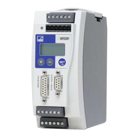
- Page 1 ENGLISH DEUTSCH Operating Manual Bedienungsanleitung MP60, MP60DP...
- Page 2 Hottinger Brüel & Kjaer GmbH Im Tiefen See 45 D-64293 Darmstadt Tel. +49 6151 803-0 Fax +49 6151 803-9100 info@hbkworld.com www.hbkworld.com Mat.: DVS: A05958 01 X00 00 04.2023 E Hottinger Brüel & Kjaer GmbH Subject to modifications. All product descriptions are for general information only.
- Page 3 ENGLISH DEUTSCH Operating Manual MP60, MP60DP...
- Page 4 ... . 6.2.1 External supply voltage for control outputs (MP60) .....
- Page 5 ..............MP60, MP60DP...
- Page 6 Intended use The MP60 and MP60DP modules with the connected transducers are to be used exclusively for measuring tasks and directly associated control tasks. Use for any purpose other than the above is deemed improper use.
- Page 7 When cleaning, ensure that no liquid gets into the device or connections. Residual dangers The scope of supply and performance of the MP60 and MP60DP covers only a small area of measurement technology. In addition, planners, installers and operators should plan, implement and manage the safety features of the test and measuring equipment in such a way as to minimize residual dangers.
- Page 8 Conversions and modifications The MP60 and MP60DP modules must not be modified in their design or safety features without our express consent. Any modification shall exclude all liability on our part for any resulting damage.
- Page 9 During use, compliance with the legal and safety requirements for the relevant application is also essential. The same applies to the use of accessories. Qualified personnel means persons entrusted with setting up, installing, starting up and operating the product, who possess the appropriate qualifications for their work. MP60, MP60DP SAFETY INSTRUCTIONS...
- Page 10 This marking draws your attention to information Information about the product or about handling the product. Emphasis Italics are used to emphasize and highlight text and See … identify references to sections of the manual, diagrams, or external documents and files. MP60, MP60DP MARKINGS USED...
- Page 11 Statutory waste disposal marking In accordance with national and local environmental protection and material recovery and recycling regulations, old devices that can no longer be used must be disposed of separately and not with normal household garbage. MP60, MP60DP MARKINGS USED...
- Page 12 Setup toolkit (USB to CAN interface converter) Ordering no.: 1-PME-Setup-USB General MP60 module The MP60 and MP60DP modules of the PME product line are frequency measurement modules suitable for connecting incremental encoders, frequency encoders, and HBM torque measurement flanges. The modules are set up and parameterized via a keyboard and display, or by using the PME Assistant.
- Page 13 (for MP60DP) Fig. 3.1 Block diagram of the MP60 module Information The amplifier type MP60 must be set on the DIP switch S12 (MP60) (see also page 13). 1 2 3 4 5 6 The switch positions must not be changed!
- Page 14 Set the DIP switches as shown in Fig. 4.1. Unscrew cover Fig. 4.1 Opening housing, position of DIP switches Example: means 1 2 3 4 5 6 Fig. 4.2 Switch convention MP60, MP60DP AMPLIFIER SETTINGS WITH DIP SWITCHES...
- Page 15 1 2 3 4 5 6 Analog Synchronization Amplifier Termination Frequency input, output function function (master) type resistor 120 Ω reference zero; (10 V) (OFF) internal switch ing threshold (balanced) The switch positions must not be changed! MP60, MP60DP AMPLIFIER SETTINGS WITH DIP SWITCHES...
- Page 16 Depending on transducer Activate (F1, F2 reference zero to ON) with balanced output signals and long measurement leads (u100 m). Reference zero 1 2 3 1 2 3 1 2 3 Fig. 4.3 Amplifier adjustment MP60, MP60DP AMPLIFIER SETTINGS WITH DIP SWITCHES...
- Page 17 1 2 3 4 5 6 Fig. 4.4 Amplifier adjustment (continued) Bus termination resistor Toggle switch for termination resistor (see also page 24) Fig. 4.5 Switch for CAN bus termination resistor (schematic diagram) MP60, MP60DP AMPLIFIER SETTINGS WITH DIP SWITCHES...
- Page 18 MOUNTING/DISMOUNTING Fig. 5.1 Mounting on a support rail Fig. 5.2 Dismounting CAUTION The support rail must be connected to protective conductor potential MP60, MP60DP MOUNTING/DISMOUNTING...
- Page 19 Installing a second spring for more stable mounting of the module on the support rail Interconnecting multiple modules Ribbon cable female connector Subsequent devices are inter connected via this connector. Color coding on pin 1 58 mm Recommended gap for ribbon cable female connectors Fig. 5.4 Connecting a ribbon cable MP60, MP60DP MOUNTING/DISMOUNTING...
- Page 20 (24 V level), analog output Plug terminal 4: Galvanically isolated control outputs (24 V level), external supply of control inputs Galvanic isolation referred to measuring amplifier (measuring circuit), and control inputs and outputs have a common reference potential MP60, MP60DP CONNECTION...
- Page 21 IN = digital input, OUT = digital output For more detailed information on inputs and outputs, see section 8, page 43. ATTENTION: If the mains power to the MP60 module fails, all control outputs will be set to 0 V. Fig. 6.1 Plug terminal assignment...
- Page 22 The 4 plug terminals are coded, to prevent confusion when plugging them into the 4 sockets. The sockets have coding tabs; the plug terminals have coding pins. 6.2.1 External supply voltage for control outputs (MP60) Example: PLC connection MP60 module Relay max.
- Page 23 Rotational speed measurement signal, F2 (+), 25 V Measure (5...30 V) peak-to-peak (90° phase-shifted to detect ment shaft direction of rotation) Hsg. Cable shield Rotational speed measurement signal, F1 (+), 25 V (5...30 V) peak-to-peak Transducer error Fig. 6.3 MP60 connection MP60, MP60DP CONNECTION...
- Page 24 Frequency, pulse counter, incremental transducer (unbalanced signals) Connection A Ground Rotational speed measurement signal, f1, 0° F1 (+), 0° Cable shield Rotational speed measurement signal, f2, 90° F2 (+), 90° Zero index (+) Transducer error Fig. 6.4 MP60 connection MP60, MP60DP CONNECTION...
- Page 25 The CAN bus is connected via plug terminal 1. A maximum of 32 CAN nodes may be connected in one bus segment. The CAN bus requires a 120 Ω. A termination resistor is integrated into the MP60 module, and is activated by toggle-switch S14 (see page 15).
- Page 26 CAN bus operation with multiple modules (max. 32 under the standard) Information If the first or last device in the bus line is not a PME module, a 120 W resistor must be connected to each of these external devices. MP60, MP60DP CONNECTION...
- Page 27 Connect the PROFIBUS cable to the MP60DP module. Make sure that a termination resistor is connected to the first and last PROFIBUS device (there is usually a slide switch on the housing of the PROFIBUS connector for the purpose). MP60, MP60DP CONNECTION...
- Page 28 Example PROFIBUS connector PROFIBUS connector Last device in the First device in bus line the bus line PROFIBUS connector slide PROFIBUS connector slide switch set to "Resistor ON" switch set to "Resistor ON" Fig. 6.9 PROFIBUS operation MP60, MP60DP CONNECTION...
- Page 29 Press briefly - advances one value at a time Key functions: − - Change from measuring mode to Select parameter/group setting mode - Select the first parameter in the group - Confirm your entry - Back to measuring mode (press for 2 seconds) MP60, MP60DP SETUP AND OPERATION...
- Page 30 Select required parameter 0.000 _ _ Hz ↓ ↑ Go to Input mode Enter numerical value or 2,000 0.5 Hz select table value Confirm Back to measuring mode: 2 sec PME asks: Save? Save?No Saving MP60, MP60DP SETUP AND OPERATION...
- Page 31 Gross signal >T< Net signal Maximum peak value signal Minimum peak value signal when active − Peak-to-peak signal Input signal V or mA Analog output signal not set Outp Inpt Status of input and output MP60, MP60DP SETUP AND OPERATION...
- Page 32 If the error message HardwOvf is displayed, refer to section 11 "Error messages/operating state (LED)", page 80. In addition, the yellow LED indicates that the MP60 is ready to start measuring. For the meanings of the other LEDs see section 11 "Error messages/operating state (LED)", page 80.
- Page 33 Tare I.PkVal Nom kHz PkMomMax I.I/O Nom kNm PkHldMax I.CAN TransdErr PkMomMin I.AddFnc MNGRP PkHldMin MNGRP Shunt ParaCod1 ParaCod2 InpFunc MNGRP Depending on the unit chosen MP60DP only Preset with DIP switches MNGRP Press to return to group MP60, MP60DP...
- Page 34 Flashes if parameter value can be edited I.CAN Press Confirm entry: I.AddFnc Notice: +/- = If a group cannot be selected, check under DIALOG Back to establish whether the group is enabled. 2 sec Back to measuring mode: MAINGRP MP60, MP60DP...
- Page 35 500 Hz ↓ ↑ Zero kNm 0.000 ‰ ↓ ↑ Bessel ↓ ↑ FiltChar Nom kHz 0.00000 Butterw l/mi ↓ ↑ Nom kNm 0.00000 Back MAINGRP ↓ ↑ Transd. Err Back MAINGRP Back MAINGRP Depending on the unit chosen MP60, MP60DP...
- Page 36 Back MAINGRP ↓ ↑ OffDlay ms PkHldMin Shunt Back MAINGRP ParaCod1 ParaCod2 ↓ ↑ The same applies to limit values 2...4 enabled InpFunc disabled Depending on the unit chosen At output2: F2 At output2: Direction of rotation Back MAINGRP MP60, MP60DP...
- Page 37 Gross Slow ↓ ↑ Output Keyboard Fast Medium PkValMax PkValMin SrNo PkVal PP HW-Vers Back MAINGRP ↓ ↑ OutR ms ↓ ↑ float PDOFrmt int32 ↓ ↑ AutoOPER Back MAINGRP For MP60DP only Depending on the unit chosen MP60, MP60DP...
- Page 38 Example: Measuring Md and N with T10F torque transducer (24 V supply) Both T10F and MP60 are factory set for balanced signals. Torque measurement Preparing measurement: Use the standard cable md-Kab149. Connect the external 24 V supply voltage also to plug terminal 4 (see page 21).
- Page 39 100 rpm/sec at 360 pulses/revolution: f = 36 kHz In this example, the F2 signal (necessary for detecting the direction of rotation) is to be evaluated. 1) The next higher frequency is to be selected as the input range, here: 100 kHz MP60, MP60DP...
- Page 40 6000 rpm then corresponds to 144 kHz (instead of 72 kHz with F2 = OFF). Switch: F2 Switch: Frq x 4 Frequency display Direction detection 2). Each edge is counted, not only the pulses; this quadruples the resolution MP60, MP60DP...
- Page 41 Switching threshold as from which the input signal is detected Suppresses interference pulses with a duration of t3.2 μs GltchFlt Zero kHz Zero kNm Set input characteristic via transducer parameters Nom kHz Nom kNm MP60, MP60DP EXPLANATION OF THE MAIN PARAMETERS...
- Page 42 Save tare value immediately after taring Filter 0.05 Hz 1 Hz 20 Hz 500 Hz 0.1 Hz 2 Hz 50 Hz 0.2 Hz 5 Hz 100 Hz 0.5 Hz 10 Hz 200 Hz MP60, MP60DP EXPLANATION OF THE MAIN PARAMETERS...
- Page 43 Use DIP switch S11 to specify the signal mode for the analog output. The following options are possible: "10 V, "20 mA, 4...20 mA Zero % Zero V EndVkNm EndV V EndV V Zero V Physical unit Zero kNm EndV kNm MP60, MP60DP EXPLANATION OF THE MAIN PARAMETERS...
- Page 44 (OnDelay). OffDlay ms Switch-off delay, as for OnDelay PkVal InputMin/ The choice of source for the peak value signal is: Gross, Net ClearPkV The peak value can be cleared. MP60, MP60DP EXPLANATION OF THE MAIN PARAMETERS...
- Page 45 Input level 24 V Tare The transition from 0 V - 24 V starts the taring process Zero The transition from 0 V - 24 V sets the current balance measurement signal to zero MP60, MP60DP EXPLANATION OF THE MAIN PARAMETERS...
- Page 46 PkMax memory contents PkMax memory contents are updated are frozen PkHldMin PkMin memory contents are PkMin memory contents are updated frozen ParaCod1 Selecting parameter sets and binary-coded inputs ParaCod2 Parameter set ParaCod2 ParaCod1 MP60, MP60DP EXPLANATION OF THE MAIN PARAMETERS...
- Page 47 The signal output over the CAN bus is selected and sent as a PDO: gross, net or max/min peak value, peak-to-peak, OFF, user when activated: automatically switched Operational AutoOPER PROFI bus Address Address setting from 3 - 123 MP60, MP60DP EXPLANATION OF THE MAIN PARAMETERS...
- Page 48 Î Î Î Î Î Î Î StillDsp Standstill indication If standstill occurs with ON selected, the following symbol is displayed LoadnmZer OFF: Zero value memory is not overwritten when parameter is changed HW Synchr Master or slave MP60, MP60DP EXPLANATION OF THE MAIN PARAMETERS...
- Page 49 CAN INTERFACE DESCRIPTION General The MP60 and MP60DP modules have a built-in CAN interface that can be used both to transmit measured values and to parameterize the module. Different baud rates can be selected up to a maximum of 1 MBaud. The interface protocol is adapted from the CANopen Standard.
- Page 50 Ñ Ñ Ñ Ñ Ñ Ñ Ñ Ñ Ñ Ñ Ñ Ñ Ñ Ñ Ñ Ñ Ñ Writing a parameter Send value (PC or PLC to MP60/ MP60DP) Ñ Ñ Ñ Ñ Ñ Ñ Ñ Ñ Ñ Ñ Ñ Ñ Ñ Ñ Ñ Ñ Ñ Ñ Ñ Ñ Ñ Ñ Ñ Ñ...
- Page 51 Ñ Ñ Ñ Ñ Ñ Ñ Ñ Ñ Ñ Ñ Ñ Ñ Ñ Ñ Ñ Ñ Ñ Ñ Response in the event of an error when reading or writing parameters: Error acknowledgment (MP60/MP60DP to PC or PLC) Ñ Ñ Ñ Ñ Ñ Ñ Ñ...
- Page 52 Ñ Ñ Ñ Ñ Ñ Ñ 1009 Manufacturer's Vis string hardware version Ñ Ñ Ñ Ñ Ñ Ñ Ñ Ñ Ñ Ñ Ñ Ñ Ñ Ñ Ñ Ñ Ñ Ñ Ñ Ñ Ñ Ñ Ñ Ñ Ñ Ñ Ñ Ñ MP60, MP60DP CAN INTERFACE DESCRIPTION...
- Page 53 Ñ Ñ Ñ Ñ Ñ Ñ Ñ Ñ Ñ Ñ Ñ 1801 0..2 2nd send PDO PDOComm parameter 1A00 0..2 1st send PDO mapping mapping 1A01 0..2 2nd send PDO mapping mapping Data structures PDO CommPar: MP60, MP60DP CAN INTERFACE DESCRIPTION...
- Page 54 Ñ Ñ Ñ Ñ Ñ Ñ Ñ Ñ Ñ Ñ Ñ SDO parameter: Index Subindex Name Data type 0022 Number of entries unsigned8 COB ID client->server unsigned32 COB ID server->client unsigned32 Node ID (optional) unsigned8 MP60, MP60DP CAN INTERFACE DESCRIPTION...
- Page 55 Warning due to tare status Emergency objects Byte Byte 0 Byte 1 Byte 2 Byte 3 Byte 4 Byte 5 Byte 6 Byte 7 Content Emergency Error Manufacturer specific error field error code register (object 1001H) MP60, MP60DP CAN INTERFACE DESCRIPTION...
- Page 56 32-bit format) – see page 65. Notice: rop, rwp: PDO mappable Index Name Format Attr. Values Sub (hex) index Measured values 2000 Gross measured integer32 value 2001 Net measured value integer32 2002 Maximum integer32 2003 Minimum integer32 2004 Peaktopeak integer32 MP60, MP60DP CAN INTERFACE DESCRIPTION...
- Page 57 Bit 9: Limit value 2 Bit 10: Limit value 3 Bit 11: Limit value 4 Bit 12: Scaling input Bit 13: Scaling output Bit 15: InCal.Err Bit 16: Transducer error Bit 17: CAN bus Off Bit 18: CAN Tx error MP60, MP60DP CAN INTERFACE DESCRIPTION...
- Page 58 Bit 5: Conditioning Bit 6: Analog output Bit 7: Limit values Bit 8: Peak values Bit 9: Inputs/outputs Bit 10: CAN Bit 11: Additional functions Bit 12: Calibration Bit 13: DP Bit 15: Lock keyboard Parameter sets MP60, MP60DP CAN INTERFACE DESCRIPTION...
- Page 59 1649: rad 1623: inch 1650: rad/s 1624: Nm 1651: km/h 1625: kNm 1652: mph 1626: FTLB 1653: ft/s 1627: INLB 1654: inoz 1628: μm/m 1629: m/s 1655: Ncm 1656: l/h 1630: m/s 1631: % 1657: l/mi MP60, MP60DP CAN INTERFACE DESCRIPTION...
- Page 60 Transducer zero kHz integer32 Value in kHz 2141 Transducer zero integer32 Value e.g. in kN phys. unit 2142 Transducer integer32 Value in kHz sensitivity kHz 2143 Transducer integer32 Value e.g. in kN sensitivity phys. unit MP60, MP60DP CAN INTERFACE DESCRIPTION...
- Page 61 Ñ Ñ Ñ Ñ Ñ Ñ Ñ 218: Peaktopeak Ñ Ñ Ñ Ñ Ñ Ñ Ñ Ñ Ñ Ñ Ñ Ñ Ñ Ñ Ñ Ñ Ñ Ñ Ñ Ñ Ñ Ñ Ñ Ñ Ñ Ñ Ñ Ñ MP60, MP60DP CAN INTERFACE DESCRIPTION...
- Page 62 Ñ Ñ Ñ Ñ Ñ Ñ Ñ Ñ 218: Peaktopeak Ñ Ñ Ñ Ñ Ñ Ñ Ñ Ñ Ñ Ñ Ñ Ñ Ñ Ñ Ñ Ñ Ñ Ñ Ñ Ñ Ñ Ñ Ñ Ñ Ñ Ñ Ñ Ñ MP60, MP60DP CAN INTERFACE DESCRIPTION...
- Page 63 Ñ Ñ Ñ Ñ Ñ Ñ Ñ 218: Peaktopeak Ñ Ñ Ñ Ñ Ñ Ñ Ñ Ñ Ñ Ñ Ñ Ñ Ñ Ñ Ñ Ñ Ñ Ñ Ñ Ñ Ñ Ñ Ñ Ñ Ñ Ñ Ñ Ñ MP60, MP60DP CAN INTERFACE DESCRIPTION...
- Page 64 0 = OFF Ñ Ñ Ñ Ñ Ñ Ñ Ñ Ñ Ñ Ñ Ñ Ñ Ñ ing parameter set Ñ Ñ Ñ Ñ Ñ Ñ Ñ Ñ Ñ Ñ Ñ Ñ Ñ Ñ Ñ MP60, MP60DP CAN INTERFACE DESCRIPTION...
- Page 65 2317 Output mode 4 unsigned16 see above Ñ Ñ Ñ Ñ Ñ Ñ Ñ Ñ Ñ Ñ Ñ Ñ Ñ Ñ Ñ Ñ Ñ Ñ Ñ Ñ Ñ Ñ Ñ Ñ Ñ Ñ Ñ Ñ MP60, MP60DP CAN INTERFACE DESCRIPTION...
- Page 66 Ñ Ñ Ñ Ñ Ñ Ñ Ñ Ñ 2405 Device address unsigned8 1...127 Ñ Ñ Ñ Ñ Ñ Ñ Ñ Ñ Ñ Ñ Ñ Ñ Ñ Ñ Ñ Ñ Ñ Ñ Ñ Ñ Ñ Ñ Ñ Ñ Ñ Ñ Ñ Ñ MP60, MP60DP CAN INTERFACE DESCRIPTION...
- Page 67 Ñ Ñ Ñ Ñ Ñ Ñ Ñ 3001 Net measured value float Ñ Ñ Ñ Ñ Ñ Ñ Ñ Ñ Ñ Ñ Ñ Ñ Ñ Ñ Ñ Ñ Ñ Ñ Ñ Ñ Ñ Ñ Ñ Ñ Ñ Ñ Ñ Ñ Ñ MP60, MP60DP CAN INTERFACE DESCRIPTION...
- Page 68 31D3 Analog output end value, V float Ñ Ñ Ñ Ñ Ñ Ñ Ñ Ñ Ñ Ñ Ñ Ñ Ñ Ñ Ñ Ñ Ñ Ñ Ñ Ñ Ñ Ñ Ñ Ñ Ñ Ñ Ñ Ñ MP60, MP60DP CAN INTERFACE DESCRIPTION...
- Page 69 Byte 2 Byte 3 Byte 4 Byte 5 Byte 6 Byte 7 Byte 8 0583 Read High Sub Low byte High byte identifier ackno byte byte index Measured value as float wledg index index ment MP60, MP60DP CAN INTERFACE DESCRIPTION...
- Page 70 Response from amplifier: Identifier Byte 1 Byte 2 Byte 3 Byte 4 Byte 5 Byte 6 Byte 7 Byte 8 0583 Write High Sub don't care identifier ackno byte byte index wledg index index ment MP60, MP60DP CAN INTERFACE DESCRIPTION...
- Page 71 Add an HBM device from the hardware catalog. From the hardware catalog, select the configuration you need on the Profibus. Fig. 10.1 Hardware configuration Double-click the configured entries to open the properties window and select the required parameters. MP60, MP60DP (MP60DP ONLY) PROFIBUS INTERFACE DESCRIPTION...
- Page 72 The Profibus DP parameterization telegram defines some of the parameters for DP transfer. If you are using Profibus parameterization tools which can evaluate the GSD files of GSD Revision 1, the following parameters are available for selection: MP60, MP60DP (MP60DP ONLY) PROFIBUS INTERFACE DESCRIPTION...
- Page 73 Otherwise a set zero point might be lost for example. If you are using older parameterization tools, the parameter values must be converted to decimal or hexadecimal values: MP60, MP60DP (MP60DP ONLY) PROFIBUS INTERFACE DESCRIPTION...
- Page 74 0 = disabled Disabled Enables functional control bits ity for control via 3 = enabled output control word May be automatically changed by your parameterization tool Tab. 10.2 Content of the parameterization telegram MP60, MP60DP (MP60DP ONLY) PROFIBUS INTERFACE DESCRIPTION...
- Page 75 Only one configuration entry is available. The special identifier format must be used for it. The manufacturer-specific data specifies the content, and so also the length, of the input data, with a length of 2 bytes. MP60, MP60DP (MP60DP ONLY) PROFIBUS INTERFACE DESCRIPTION...
- Page 76 The length of the input data is the sum of all the data lengths selected for transmission in words. If you select the 32-bit format and the float format for measured values, the length values in brackets must be used. So the configuration telegram format is: MP60, MP60DP (MP60DP ONLY) PROFIBUS INTERFACE DESCRIPTION...
- Page 77 (display, CAN bus) must be used as a basis. Status 1 Name Meaning MeasVOvfl Measured value overflow AOutOvfl Analog output overflow ScalErr Incorrect scaling EEPROMErr EEPROM (parameter set) incorrect Status of limit switch 1 Status of limit switch 2 MP60, MP60DP (MP60DP ONLY) PROFIBUS INTERFACE DESCRIPTION...
- Page 78 Net signal overflow AOutOvfl Analog output overflow MaxOvfl Maximum overflow MinOvfl Minimum overflow NegOvfl Overflow in negative direction Status of limit switch 1 Status of limit switch 2 Status of limit switch 3 MP60, MP60DP (MP60DP ONLY) PROFIBUS INTERFACE DESCRIPTION...
- Page 79 HOLDMAX 1: Freeze MAX peak value memory HOLDMIN 1: Freeze MIN peak value memory PAR1 Parameter set selection bit 1 PAR2 Parameter set selection bit 2 10..15 Reserved Tab. 10.7 Control word content MP60, MP60DP (MP60DP ONLY) PROFIBUS INTERFACE DESCRIPTION...
- Page 80 Hardware overflow ADC overflow Gross overflow Net overflow Analog output overflow Maximum overflow Minimum overflow Reserved 0..3 Reserved Input characteristic scaling error Output characteristic scaling error Nominal (rated) value exceeded Defective working standard calibration MP60, MP60DP (MP60DP ONLY) PROFIBUS INTERFACE DESCRIPTION...
- Page 81 Octet Value Meaning Transducer error 1...7 Reserved Tab. 10.8 Diagnosis content MP60, MP60DP (MP60DP ONLY) PROFIBUS INTERFACE DESCRIPTION...
- Page 82 − − − − − − − Peak-to-peak signal CntOvfl InCalErr − − − − − − − Input signal CntOvfl AnlgOvfl − − − − − − − AScalErr InCalErr Analog output signal Imp, kImp MP60, MP60DP ERROR MESSAGES/OPERATING STATE (LED)
- Page 83 No valid initial calibration Restart, send the PME to the values manufacturer (HBM) CAN Tx PDOs are not accepted on the Check CAN bus configuration ±1000000 is outputted on the CAN bus See page 40 MP60, MP60DP ERROR MESSAGES/OPERATING STATE (LED)
- Page 84 Information The MP60 can indicate transducer errors generated by the torque sensor. But to do this, the error signal from the torque sensor must be connected across pin 7 of the transducer plugs (15-pin sub-D plugs). The "transducer error" function in the MP60 must also be activated.
- Page 85 DATA_EX (cyclic data traffic) ERROR (bus error) The LEDs indicate the operating states (ready for measurement, overflow, etc.) of the MP60DP. But (as in the MP60) the PROFIBUS state is indicated, not the CAN state. Operating state: LED color State...
- Page 86 Configuring, 30 Emergency object, 53 Connect transducer, 21 Error acknowledgement, 49 Connecting Error code, 53 CAN interface, 23 Supply voltage, 20 Error message, 30, 80, 81 Connecting a ribbon cable, 17 Errors, 29 Factory settings, 13, 14 MP60, MP60DP INDEX...
- Page 87 Limit value switch, 60, 67 Line termination resistor, 14 PROFI bus, 45 Loading, 39 Profile, 45 Mains power failure, 19 Reference zero, 13, 46 Master/slave, 23 Remote controls, 43 Measured value, 54, 65 Ribbon cable, 23 Measuring mode, 28 MP60, MP60DP INDEX...
- Page 88 Switching threshold, Loading, Saving, 39 Synchronization, 18, 23 Tare, 40 Termination resistor, 15, 23 Torque shaft, 10 Transducer, 57, 66 Transducer connection, 18 Trigger level, 58 Voltage supply, 18, 19 Zero balance, 40 Zero index, 39, 58, 59 MP60, MP60DP INDEX...
- Page 89 ENGLISH DEUTSCH Bedienungsanleitung MP60, MP60DP...
- Page 90 Versorgungsspannung und Steuerein‐/ausgänge und CAN Schnittstelle ..6.2.1 Externe Versorgungsspannung für die Steuerausgänge (MP60) ..Aufnehmer anschließen ..........
- Page 91 ........... . . MP60, MP60DP...
- Page 92 Zuständen oder Datenverlust in der Automatisie rungseinrichtung führen. Bestimmungsgemäße Verwendung Die Module MP60 und MP60DP mit den angeschlossenen Aufnehmern sind ausschließ lich für Messaufgaben und direkt damit verbundene Steuerungsaufgaben zu verwenden. Jeder darüber hinausgehende Gebrauch gilt als nicht bestimmungsgemäß.
- Page 93 Achten Sie beim Reinigen darauf, dass keine Flüssigkeit in das Gerät oder an die An schlüsse gelangt. Restgefahren Der Leistungs‐ und Lieferumfang des MP60 bzw. MP60DP deckt nur einen Teilbereich der Messtechnik ab. Sicherheitstechnische Belange der Messtechnik sind zusätzlich vom Anlagenplaner/Ausrüster/Betreiber so zu planen, zu realisieren und zu verantworten, dass Restgefahren minimiert werden.
- Page 94 Greenline-Schirmführung verwenden (den Schirm des Aufnehmer kabels auf das Steckergehäuse legen). Die verwendeten Kabel der digitalen Ein‐ und Ausgänge des MP60/MP60DP sollten nicht länger als 30 Meter sein und das Gebäude, in dem die Anlage steht, nicht verlassen. An...
- Page 95 Rechts‐ und Sicherheitsvorschriften zu beachten. Sinngemäß gilt dies auch bei Verwen dung von Zubehör. Qualifiziertes Personal sind Personen, die mit Aufstellung, Montage, Inbetriebsetzung und Betrieb des Produktes vertraut sind und die über die ihrer Tätigkeit entsprechende Quali fikationen verfügen. MP60, MP60DP SICHERHEITSHINWEISE...
- Page 96 Dokumente und Dateien. Auf dem Gerät angebrachte Symbole CE-Kennzeichnung Mit der CE‐Kennzeichnung garantiert der Hersteller, dass sein Produkt den Anforderungen der relevanten EG‐Richtlinien ent spricht (die Konformitätserklärung finden Sie auf der Website von HBM (www.hbm.com) unter HBMdoc). MP60, MP60DP VERWENDETE KENNZEICHNUNGEN...
- Page 97 Gesetzlich vorgeschriebene Kennzeichnung zur Entsorgung Nicht mehr gebrauchsfähige Altgeräte sind gemäß den nationa len und örtlichen Vorschriften für Umweltschutz und Rohstoff rückgewinnung getrennt von regulärem Hausmüll zu entsorgen. MP60, MP60DP VERWENDETE KENNZEICHNUNGEN...
- Page 98 Setup‐Toolkit (Schnittstellenumsetzer USB auf CAN) Bestell‐Nr.: 1-PME-Setup-USB Allgemeines Modul MP60 Die Module MP60 und MP60DP der Produktlinie PME sind Frequenz‐Messmodule, die für den Anschluss von Inkrementalgebern, Frequenzgebern und HBM‐Drehmoment‐Mess flanschen geeignet ist. Eingestellt und parametriert werden die Module über Tastatur und Display oder mit Hilfe des PME-Assistenten.
- Page 99 PRO FIBUS‐DP‐Schnitt stelle (für MP60DP) Abb. 3.1 Blockschaltbild des Moduls MP60 Information Auf dem DIP‐Schalter S12 (MP60) muss der Verstärkertyp MP60 eingestellt sein (siehe auch Seite 13). 1 2 3 4 5 6 Schalterpositionen dürfen nicht verändert werden! MP60, MP60DP...
- Page 100 Analogausgang, Synchronisierung, Bus‐Abschlusswiderstand, Flanken steilheit Zum Einstellen der DIP‐Schalter müssen Sie wie in Abb. 4.1 gezeigt vorgehen. Deckel abschrauben Abb. 4.1 Gehäuse öffnen, Lage der DIP‐Schalter Beispiel: bedeutet 1 2 3 4 5 6 Abb. 4.2 Schalterkonvention MP60, MP60DP VERSTÄRKEREINSTELLUNGEN MIT DIP‐SCHALTERN...
- Page 101 1 2 3 4 5 6 1 2 3 4 5 6 Analog Keine Keine Synchronisation Verstärker Abschluss Frequenz ausgang Funktion Funktion (Master) widerstand eingang, (10 V) 120 Ω Referenznull; (AUS) Interne Schalt Schalterpositionen schwelle dürfen nicht (symmetrisch) verändert werden! MP60, MP60DP VERSTÄRKEREINSTELLUNGEN MIT DIP‐SCHALTERN...
- Page 102 1 2 3 Ua”;siehe Seite 33 Aufnehmerabhängig Zuschalten (F1, F2 Referenznull auf EIN) bei symmetrischen Ausgangssignalen und langen Messleitungen (u100 m). Referenznull 1 2 3 1 2 3 1 2 3 Abb. 4.3 Verstärker einstellen MP60, MP60DP VERSTÄRKEREINSTELLUNGEN MIT DIP‐SCHALTERN...
- Page 103 Synchronisation Master 1 2 3 4 5 6 Slave 1 2 3 4 5 6 Abb. 4.4 Verstärker einstellen (Fortsetzung) Bus‐Abschlusswiderstand Kippschalter für Abschlusswiderstand (siehe auch Seite 24) Abb. 4.5 Schalter für Abschlusswiderstand CAN‐Bus (Prinzipbild) MP60, MP60DP VERSTÄRKEREINSTELLUNGEN MIT DIP‐SCHALTERN...
- Page 104 MONTAGE/DEMONTAGE Abb. 5.1 Montieren auf eine Tragschiene Abb. 5.2 Demontage VORSICHT Die Tragschiene muss auf Schutzleiterpotential liegen. MP60, MP60DP MONTAGE/DEMONTAGE...
- Page 105 Einbau einer zweiten Feder für eine stabilere Befestigung des Moduls auf der Hutschiene Mehrere Module verbinden Flachbandkabel‐Buchsenstecker Folgegeräte werden über diesen Stecker miteinander verbunden. Farbliche Kennzeich nung an Pin 1 58 mm empfohlener Abstand der Flach bandkabel‐ Buchsenstecker Abb. 5.4 Flachbandkabel anschließen MP60, MP60DP MONTAGE/DEMONTAGE...
- Page 106 2zeiliges LCD‐Display Drucksensitive Bedientasten Aufnehmeranschluss (15poliger Sub‐D‐Stecker) Steckklemme 3: Potentialgetrennte Steuerein gänge (24 V‐Pegel), Analogausgang Steckklemme 4: Potentialgetrennte Steuerausgänge (24 V‐Pegel), Externe Versorgung der Steuereingänge Potentialtrennung bezogen auf Messverstärker (Messkreis) und Versorgungsspannung Steuereingänge und Steuerausgänge haben gemeinsames Bezugspotential MP60, MP60DP ANSCHLIEßEN...
- Page 107 Schnittstelle Es stehen vier abziehbare Steckklemmen für das Anschließen zur Verfügung. Spannungsversorgung anschließen WARNUNG Das Modul MP60 muss an eine externe Spannung von 18-30 V (24 V angeschlossen werden. - Aderenden der Spannungsversorgung verdrillen und mit Aderendhülsen versehen. - Aderenden an die Steckklemme 1 schrauben.
- Page 108 Die 4 Steckklemmen sind kodiert, um sie verwechslungssicher auf die 4 Buchsen aufstek ken zu können. Die Buchsen sind mit Kodierreitern, die Steckklemmen mit Kodierstiften versehen. 6.2.1 Externe Versorgungsspannung für die Steuerausgänge (MP60) Beispiel: SPS‐Anschluss Modul MP60 Relais max. 100 mA OUT3 max.
- Page 109 T34FN Anschluss B Betriebsspannungsnull Messsignal Drehzahl, F2 (+), 25 V (5...30 V) Spit Mess ze‐Spitze (90° phasenverschoben für Drehrich welle tungserkennung) Geh. Kabelschirm Messsignal Drehzahl, F1 (+), 25 V (5...30 V) Spitze‐Spitze Aufnehmerfehler Abb. 6.3 Anschluss MP60 MP60, MP60DP ANSCHLIEßEN...
- Page 110 Messsignal Drehzahl, F2 (+), 90° Nullindex (+) Nullindex (-) Aufnehmerfehler Frequenz, Impulszähler, Inkrementalaufnehmer (asymmetrische Signale) Anschluss A Masse f1, 0° Messsignal Drehzahl, F1 (+), 0° Kabelschirm Geh. f2, 90° Messsignal Drehzahl, F2 (+), 90° Nullindex (+) Aufnehmerfehler Abb. 6.4 Anschluss MP60 MP60, MP60DP ANSCHLIEßEN...
- Page 111 Der CAN‐Bus wird über die Steckklemme 1 angeschlossen. In einem Bus‐Segment dürfen maximal 32 CAN‐Teilnehmer angeschlossen werden. Der CAN‐Bus benötigt im ersten und letzten Busteilnehmer einen Abschlusswiderstand von 120 Ω. Im Modul MP60 ist ein Abschlusswiderstand integriert, der durch den Kipp schalter S14 aktiviert wird (siehe Seite 15). MP60, MP60DP...
- Page 112 (siehe Seite 15) widerstand zuschalten Abb. 6.7 CAN‐Bus‐Betrieb mit mehreren Modulen (nach Norm maximal 32) Information Ist das erste beziehungsweise letzte Gerät in der Bus‐Leitung kein PME‐Modul, so muss an diesen Fremdgeräten jeweils ein 120 W‐Widerstand zugeschaltet werden. MP60, MP60DP ANSCHLIEßEN...
- Page 113 Setup‐Programm die gewünschte PROFIBUS‐Adresse einstellen. Schließen Sie die PROFIBUS‐Leitung an das Modul MP60DP an. Achten Sie darauf, dass am ersten und letzten PROFIBUS‐Teilnehmer ein Abschlusswiderstand von zuge schaltet ist (am Gehäuse des PROFIBUS‐Steckers befindet sich hierzu üblicherweise ein Schiebeschalter). MP60, MP60DP ANSCHLIEßEN...
- Page 114 Beispiel PROFIBUS‐Ste PROFIBUS‐Ste cker cker Letztes Gerät in Erstes Gerät in der Busleitung der Busleitung Schiebeschalter des PROFIBUS‐ Schiebeschalter des PRO Steckers auf “Widerstand EIN” FIBUS‐Steckers auf “Wider stand EIN” Abb. 6.9 PROFIBUS‐Betrieb MP60, MP60DP ANSCHLIEßEN...
- Page 115 Taste kurz drücken -> Wert einzeln weiterschalten Funktion der Tasten − - Vom Messbetrieb in den Einstellbetrieb Parameter/Gruppe auswählen wechseln - Den ersten Parameter innerhalb der Gruppe wählen. - Eingabe bestätigen - Zurück in den Messbetrieb (2 Sek drük ken) MP60, MP60DP EINSTELLEN UND BEDIENEN...
- Page 116 Gewünschten Parameter 0.000 _ _ Hz wählen ↓ ↑ In Eingabemodus gehen Zahlenwert eingeben oder 2.000 0.5 Hz Tabellenwert wählen Bestätigen Zurück in den 2 Sek PME fragt: Speichr? Messbetrieb: NEIN Speichr? speichert Nein gerade MP60, MP60DP EINSTELLEN UND BEDIENEN...
- Page 117 -18.00 Statusfeld Einheit Symbol im Statusfeld Anzeigemodus kein Zeichen Bruttosignal >T< Nettosignal Maximales Spitzenwertsignal Minimales Spitzenwertsignal wenn aktiv − Spitze/Spitze‐Signal Eingangssignal V oder mA Analogausgangssignal gesetzt, nicht gesetzt Ausg Eing Zustand von Eingang und Ausgang MP60, MP60DP EINSTELLEN UND BEDIENEN...
- Page 118 Erscheint hier die Fehlermeldung HardwOvf, lesen Sie bitte in Kapitel 11 ”Fehlermeldungen/Betriebszustand (LED)”, Seite 82 weiter. Zusätzlich zeigt Ihnen die gelbe LED die Messbereitschaft des MP60 an. Die weiteren Bedeutungen der LED entnehmen Sie dem Kapitel 11 ”Fehlermeldungen/Betriebszustand (LED)”, Seite 82.
- Page 119 Null kNm Tarier. E.Spitzw Nenn kHz SpMomMax E.E/A Nenn kNm SpHltMax E.CAN AufnFhlr SpMomMin E.Zusatz HPTGR SpHltMin HPTGR Shunt ParaCod1 ParaCod2 EingFkt. HPTGR Je nach gewählter Einheit Nur bei MP60DP Voreingestellt mit DIP‐Schaltern, HPTGR mit zurück zur Gruppe MP60, MP60DP...
- Page 120 E.E/A Blinkt, wenn Parameterwert editierbar E.CAN drücken Eingabe bestätigen: E.Zusatz Hinweis: +/- = oder Wenn sich eine Gruppe nicht anwählen läßt, überprüfen Sie zurück unter DIALOG, ob die Gruppe freigegeben ist. 2 sec Zurück in den Messbetrieb: HAUPTGRP MP60, MP60DP...
- Page 121 HAUPTGRP 500Hz ↓ ↑ Null kNm 0.000 ‰ ↓ ↑ Bessel ↓ ↑ FiltChar Nenn kHz 0.00000 Butterw l/mi ↓ ↑ Nenn kNm 0.00000 zurück HAUPTGRP ↓ ↑ Aufn Fhlr zurück HAUPTGRP zurück HAUPTGRP je nach gewählter Einheit MP60, MP60DP...
- Page 122 EinVz ms SpMomMin zurück HAUPTGRP ↓ ↑ AusVz ms SpHltMin Shunt zurück ParaCod1 HAUPTGRP ParaCod2 ↓ ↑ Gilt analog für die Grenzwerte 2...4 frei EingFkt. gesprt. je nach gewählter Einheit bei Ausgang2: F2 bei Ausgang2: Drehrichtung zurück HAUPTGRP MP60, MP60DP...
- Page 123 ↓ ↑ Brutto langsam ↓ ↑ Ausgabe Tastatur schnell Netto mittel SpwtMax SpwtMin SpwtS-S HW-Vers zurück HAUPTGRP ↓ ↑ AusgR ms ↓ ↑ float PDO‐Frmt int32 ↓ ↑ AutoOPER zurück Nur bei MP60DP HAUPTGRP Je nach gewählter Einheit MP60, MP60DP...
- Page 124 Beispiel: Messen von Md und N mit Drehmoment‐Aufnehmer T10F (24 V‐Versorgung) Sowohl T10F als auch der MP60 sind werkseitig auf symmetrische Signale eingestellt. Drehmoment‐Messung Vorbereitung der Messung: Verwenden Sie das Standardkabel md‐Kab149. Schließen Sie die externe Versorgungsspannung von 24 V auch an die Steckklemme 4 an (siehe Seite 21).
- Page 125 6000 U/min = 6000/60 U/sec = 100 U/sec bei 360 Impulsen/Umdrehung: f = 36 kHz In diesem Beispiel soll das F2‐Signal (notwendig zur Drehrichtungserkennung) ausgewer tet werden. 1) Als Eingangsbereich ist die nächst höhere Frequenz zu wählen, hier: 100 kHz MP60, MP60DP...
- Page 126 6000 U/min entsprechen dann 144 kHz (statt 72 kHz bei F2 = AUS). Schalter: F2 Schalter: Frq x 4 Frequenzanzeige Richtungserkennung nein nein 2). Es wird jede Flanke gezählt, nicht nur die Impulse; dadurch vervierfacht sich die Auflösung MP60, MP60DP...
- Page 127 Definition durch ein (-) angezeigt. Schaltsw Schaltschwelle ab der das Eingangssignal erkannt wird Unterdrückt Störimpulse mit einer Dauer von t3,2 μs GltchFlt Null kHz Null kNm Eingangskennlinie über Aufnehmerkennwerte einstellen Nenn kHz Nenn kNm MP60, MP60DP ERKLÄRUNG DER WESENTLICHEN PARAMETER...
- Page 128 >T<speich Tarawert unmittelbar nach dem Tarieren speichern Filter 0,05 Hz 1 Hz 20 Hz 500 Hz 0,1 Hz 2 Hz 50 Hz 0,2 Hz 5 Hz 100 Hz 0,5 Hz 10 Hz 200 Hz MP60, MP60DP ERKLÄRUNG DER WESENTLICHEN PARAMETER...
- Page 129 Mit den DIP‐Schaltern S11 legen Sie den Signalmodus für den Analogausgang fest. Folgende Optionen sind möglich: "10 V, "20 mA, 4...20 mA Null % Null V EndwkNm Endw V Endw V Null V Physikalische Null kNm Endw kNm Einheit MP60, MP60DP ERKLÄRUNG DER WESENTLICHEN PARAMETER...
- Page 130 Änderung erst nach der Verzögerungs zeit (EinVz) am Ausgang aus. AusVz ms Ausschaltverzögerung, wie EinVz SPITZ Eing.Min/ Als Quelle des Spitzenwertsignales kann gewählt werden: Brutto, Netto, SpLöschn Der Spitzenwert kann gelöscht werden. MP60, MP60DP ERKLÄRUNG DER WESENTLICHEN PARAMETER...
- Page 131 Ausgangssignal wird invertiert (pos.Log) oder nicht inver Aus1...4 tiert (neg.Log). Die aufgeführten Funktionen können den Steuerkontakten (Eingängen/Ausgängen) frei zugeordnet werden. Funktionen Eingangspegel 0 V Eingangspegel 24 V Tarieren bei Übergang von 0 V - 24 V wird die Tarierung gestartet MP60, MP60DP ERKLÄRUNG DER WESENTLICHEN PARAMETER...
- Page 132 Betriebsart Momentanwert SpMin für SpMin SpHltMax Speicherinhalt SpMax wird Speicherinhalt SpMax wird aktualisiert eingefroren SpHltMin Speicherinhalt SpMin wird Speicherinhalt SpMin wird aktualisiert eingefroren ParaCod1 Auswahl von Parametersätzen und binär codierten Eingängen ParaCod2 Parametersatz ParaCod2 ParaCod1 MP60, MP60DP ERKLÄRUNG DER WESENTLICHEN PARAMETER...
- Page 133 PDO‐Frmt Das über den CAN‐Bus ausgegebene Signal wird gewählt und als PDO versendet: Brutto, Netto oder Spitzenwert max/min., Spitze/Spitze, AUS, Benutzer AutoOPER wenn aktiviert: automatisch Operational geschaltet PROFI‐Bus Adresse Adresseinstellung von 3 - 123 MP60, MP60DP ERKLÄRUNG DER WESENTLICHEN PARAMETER...
- Page 134 Î Î Î Î Î Î Î Fundament Î Î Î Î Î Î Î StillAnz Stillstandsanzeige. Ist Stillstand eingetreten und EIN gewählt, erscheint das Zeichen LadnmNul AUS: Nullwertspeicher wird nicht überschrieben bei Parameterwechsel HW‐Synchr Master oder Slave MP60, MP60DP ERKLÄRUNG DER WESENTLICHEN PARAMETER...
- Page 135 SCHNITTSTELLENBESCHREIBUNG CAN Allgemeines Die Module MP60 und MP60DP verfügen über eine eingebaute CAN‐Schnittstelle, über die sowohl Messwerte übertragen werden können als auch die Parametrierung des Mo duls vorgenommen werden kann. Die Baudrate ist wählbar, maximal ist 1 MBaud möglich. Das Protokoll der Schnittstelle orientiert sich am CANopen Standard.
- Page 136 Ñ Ñ Ñ Ñ Ñ Ñ Ñ Ñ Ñ Ñ Ñ Ñ Ñ Ñ Ñ Ñ Ñ Schreiben eines Parameters Wert senden (PC oder SPS an MP60/ MP60DP) Ñ Ñ Ñ Ñ Ñ Ñ Ñ Ñ Ñ Ñ Ñ Ñ Ñ Ñ Ñ Ñ Ñ Ñ Ñ Ñ Ñ Ñ Ñ Ñ...
- Page 137 Ñ Ñ Ñ Ñ Ñ Ñ Ñ Ñ Ñ Ñ Ñ Ñ Ñ Ñ Ñ Ñ Ñ Ñ Ñ Ñ Ñ Ñ Ñ Ñ Ñ Quittung (MP60/ MP60DP an PC oder SPS) Ñ Ñ Ñ Ñ Ñ Ñ Ñ Ñ Ñ Ñ Ñ Ñ Ñ Ñ Ñ Ñ Ñ Ñ Ñ Ñ Ñ Ñ Ñ Ñ Ñ...
- Page 138 Ñ Ñ Ñ Ñ Ñ Ñ Ñ Version String Ñ Ñ Ñ Ñ Ñ Ñ Ñ Ñ Ñ Ñ Ñ Ñ Ñ Ñ Ñ Ñ Ñ Ñ Ñ Ñ Ñ Ñ Ñ Ñ Ñ Ñ Ñ Ñ MP60, MP60DP SCHNITTSTELLENBESCHREIBUNG CAN...
- Page 139 Ñ Ñ Ñ Ñ Ñ Ñ Ñ Ñ Ñ Ñ Ñ Ñ Ñ Ñ Ñ Ñ Ñ Ñ Ñ Ñ Ñ Ñ Ñ Ñ Ñ Ñ Ñ Ñ Ñ Ñ Ñ Ñ Ñ Ñ Ñ Ñ Ñ 1801 0..2 2. Sende‐PDO‐Parame PDO Comm MP60, MP60DP SCHNITTSTELLENBESCHREIBUNG CAN...
- Page 140 PDO gültig PDO ungültig RTR erlaubt RTR nicht erlaubt 11 bit ID 29 bit ID 28..0 CAN‐ID PDO Mapping: Index Subindex Name Datentyp 0021 Anzahl gemappter Objekte unsigned8 1. gemapptes Objekt unsigned32 2. gemapptes Objekt unsigned32 unsigned32 MP60, MP60DP SCHNITTSTELLENBESCHREIBUNG CAN...
- Page 141 Fehlercode ‐ zusätzliche Information: Wert Bedeutung Kein Fehler Übertragungsfehler Systemfehler unbekannter Befehl falsche Parameterzahl falscher Parameterwert Fehler wegen Filterfrequenz Verstärker übersteuert Befehl nicht ausführbar fehlerhafte Kanalwahl Fehler beim Messen Fehler beim Triggern Fehler beim Messbereich Fehler beim Tarieren MP60, MP60DP SCHNITTSTELLENBESCHREIBUNG CAN...
- Page 142 Parameter, die auf Messwerte Bezug nehmen, sind ziffernrichtig skaliert als Long (Integer 32 Bit) codiert. Die Dezimalpunktposition ist im Objekt 2120Hex definiert. Alternativ ste hen diese Größen auch als Float‐Werte (IEEE754‐1985 Format 32 Bit) zur Verfügung (siehe Seite 67). Hinweis: rop, rwp: PDO‐Mappbar MP60, MP60DP SCHNITTSTELLENBESCHREIBUNG CAN...
- Page 143 Impuls: 0 Nachkommast. 2006 Wert Analo inte 3 Nachkommastellen gausgang V ger32 2010 Messwert‐Sta unsi Bit 0: Messw. Overflow gned8 Bit 1: Analog Ausg. Overfl. Bit 2: Skalierung fehlerhaft Bit 3: EEPROM Fehler Bit 4..7: Grenzwert 1...4 MP60, MP60DP SCHNITTSTELLENBESCHREIBUNG CAN...
- Page 144 0: Schreiben = Löschen 2082 Seriennummer vis.string 12 Zeichen 2083 Edit‐Mode ver unsi Messwertanzeige nach be lassen gned8 schreiben mit beliebigem Wert Dialog 2101 Dialog‐Sprache unsi 1500 deutsch gned16 1501 englisch 2103 Passwort inte ger16 MP60, MP60DP SCHNITTSTELLENBESCHREIBUNG CAN...
- Page 145 Bit 15: Tastatursperre Parameter sätze 2110 Parametersatz unsi 6600: Werkseinstellung aktivieren gned16 6601: Parametersatz 1 6602: Parametersatz 2 6603: Parametersatz 3 6604: Parametersatz 4 2111 Parametersatz unsi s.o. speichern gned16 Anzeige anpassung 2120 Dezimalpunkt‐ unsi 0..5 Position gned16 MP60, MP60DP SCHNITTSTELLENBESCHREIBUNG CAN...
- Page 146 1631: % 1657: l/mi 2122 Physikalische visible 4 char Einheit String 2131 Messbereich unsi 533: 1 MHz gned16 534: 100 kHz 531: 20 kHz 535: 10 kHz 536: 1 kHz 1646: 5 MImp 1647: 1 GImp MP60, MP60DP SCHNITTSTELLENBESCHREIBUNG CAN...
- Page 147 Wert in kHz kennwert kHz ger32 2143 Aufnehmer inte Wert z.B. in kN kennwert phy ger32 sik. Einheit 2150 Eingangskenn inte Wert in kHz linie 1. Punkt ger32 2151 Eingangskenn inte Wert z.B. in kN linie 2.Punkt ger32 MP60, MP60DP SCHNITTSTELLENBESCHREIBUNG CAN...
- Page 148 Ñ Ñ Ñ Ñ Ñ Ñ Ñ Ñ Ñ (Spannung/ 292: 4..20 mA Strom) Ñ Ñ Ñ Ñ Ñ Ñ Ñ Ñ Ñ Ñ Ñ Ñ Ñ Ñ Ñ Ñ Ñ Ñ Ñ Ñ Ñ Ñ Ñ Ñ Ñ Ñ Ñ Ñ MP60, MP60DP SCHNITTSTELLENBESCHREIBUNG CAN...
- Page 149 2218 Status Grenz unsi wert 1 gned8 Ñ Ñ Ñ Ñ Ñ Ñ Ñ Ñ Ñ Ñ Ñ Ñ Ñ Ñ Ñ Ñ Ñ Ñ Ñ Ñ Ñ Ñ Ñ Ñ Ñ Ñ Ñ Ñ Ñ MP60, MP60DP SCHNITTSTELLENBESCHREIBUNG CAN...
- Page 150 Ñ Ñ Ñ Ñ Ñ Ñ Ñ Ñ Ñ Grenzwert 3 ger32 Ñ Ñ Ñ Ñ Ñ Ñ Ñ Ñ Ñ Ñ Ñ Ñ Ñ Ñ Ñ Ñ Ñ Ñ Ñ Ñ Ñ Ñ Ñ Ñ Ñ Ñ Ñ Ñ MP60, MP60DP SCHNITTSTELLENBESCHREIBUNG CAN...
- Page 151 Ñ Ñ Ñ Ñ Ñ Ñ Ñ Ñ Ñ Ñ icher freigeben gned16 0: gesperrt Ñ Ñ Ñ Ñ Ñ Ñ Ñ Ñ Ñ Ñ Ñ Ñ Ñ Ñ Ñ Ñ Ñ Ñ Ñ Ñ Ñ Ñ Ñ Ñ Ñ Ñ Ñ Ñ Ñ MP60, MP60DP SCHNITTSTELLENBESCHREIBUNG CAN...
- Page 152 Ñ Ñ Ñ Ñ Ñ Ñ Ñ Ñ Ñ gned16 Ñ Ñ Ñ Ñ Ñ Ñ Ñ Ñ Ñ Ñ Ñ Ñ Ñ Ñ Ñ Ñ Ñ Ñ Ñ Ñ Ñ Ñ Ñ Ñ Ñ Ñ Ñ Ñ MP60, MP60DP SCHNITTSTELLENBESCHREIBUNG CAN...
- Page 153 Ñ Ñ Ñ Ñ Ñ Ñ Ñ Ñ Ñ Ñ satzauswahl 1 Ñ Ñ Ñ Ñ Ñ Ñ Ñ Ñ Ñ Ñ Ñ Ñ Ñ Ñ Ñ Ñ Ñ Ñ Ñ Ñ Ñ Ñ Ñ Ñ Ñ Ñ Ñ Ñ Ñ MP60, MP60DP SCHNITTSTELLENBESCHREIBUNG CAN...
- Page 154 Ñ Ñ Ñ Ñ Ñ Ñ Ñ Ñ Ñ 2610 Tarieren unsi 1: Tarieren gned8 Ñ Ñ Ñ Ñ Ñ Ñ Ñ Ñ Ñ Ñ Ñ Ñ Ñ Ñ Ñ Ñ Ñ Ñ Ñ Ñ Ñ Ñ Ñ Ñ Ñ Ñ Ñ Ñ MP60, MP60DP SCHNITTSTELLENBESCHREIBUNG CAN...
- Page 155 Ñ Ñ Ñ Ñ Ñ Ñ Ñ sche Einheit Ñ Ñ Ñ Ñ Ñ Ñ Ñ Ñ Ñ Ñ Ñ Ñ Ñ Ñ Ñ Ñ Ñ Ñ Ñ Ñ Ñ Ñ Ñ Ñ Ñ Ñ Ñ Ñ Ñ MP60, MP60DP SCHNITTSTELLENBESCHREIBUNG CAN...
- Page 156 Ñ Ñ Ñ Ñ Ñ Ñ 3247 Hysterese Grenzwert 4 float Ñ Ñ Ñ Ñ Ñ Ñ Ñ Ñ Ñ Ñ Ñ Ñ Ñ Ñ Ñ Ñ Ñ Ñ Ñ Ñ Ñ Ñ Ñ Ñ Ñ Ñ Ñ Ñ MP60, MP60DP SCHNITTSTELLENBESCHREIBUNG CAN...
- Page 157 Einstellen der Filterfrequenz auf 200 Hz. Protokoll an den Verstärker: Identifier 1.Byte 2.Byte 3.Byte 4.Byte 5.Byte 6.Byte 7.Byte 8.Byte 0603 CAN‐ schrei Index Index Subin Low‐Byte High‐ don't care Identifier Low‐ High‐ Byte 2Byte Byte Byte 958 = (3BF Hex) MP60, MP60DP SCHNITTSTELLENBESCHREIBUNG CAN...
- Page 158 Antwort vom Verstärker: Identifier 1.Byte 2.Byte 3.Byte 4.Byte 5.Byte 6.Byte 7.Byte 8.Byte 0583 CAN‐ Quit Index Index Subin don't care Identifier tung Low‐ High‐ schrei Byte Byte MP60, MP60DP SCHNITTSTELLENBESCHREIBUNG CAN...
- Page 159 Fügen Sie ein HBM‐Gerät hinzu (Hardwarekatalog). Wählen Sie aus dem Hardwarekatalog die Konfiguration, die Sie auf dem Profibus benötigen. Abb. 10.1 Hardware‐Konfiguration Öffnen Sie durch Doppelklicken der konfigurierten Einträge das Eigenschaftsfenster und wählen Sie die gewünschten Parameter aus. MP60, MP60DP (NUR MP60DP) SCHNITTSTELLENBESCHREIBUNG PROFIBUS...
- Page 160 Die Verstärkerparameter werden wie beim MP60DP über Tastatur oder CAN‐Schnittstelle eingestellt. Das Profibus‐DP‐Parametriertelegramm legt einige Parameter für die DP‐ Übertragung fest. Wenn Sie Profibus‐Parametriertools verwenden, die GSD‐Files der GSD‐ Revision 1 verwerten können, stehen folgende Parameter zur Auswahl: MP60, MP60DP (NUR MP60DP) SCHNITTSTELLENBESCHREIBUNG PROFIBUS...
- Page 161 Funktionen im Fehlerfall gegen eine ungewollte Auslösung abzusichern, da sonst z.B. der einmal eingestellte Nullpunkt verloren gehen könnte. Falls Sie ältere Parametriertools einsetzen, müssen die Parameterwerte in Dezimal‐ oder Hexadezimalwerte umgerechnet werden: MP60, MP60DP (NUR MP60DP) SCHNITTSTELLENBESCHREIBUNG PROFIBUS...
- Page 162 1 = freigegeben Ausgangssteuer wort frei Steuerbits 0 = gesperrt gesperrt gibt Funktion für Parametersatz Steuerung über 3 = freigegeben Ausgangssteuer wort frei wird u.U. von Ihrem Parametriertool sebständig verändert Tab. 10.2 Inhalt des Parametrier‐Telegramms MP60, MP60DP (NUR MP60DP) SCHNITTSTELLENBESCHREIBUNG PROFIBUS...
- Page 163 Nachkommastellenzahl. Die Angaben, ob das 16 Bit oder ein 32 Bit‐Format verwendet wird, sowie die Anzahl der Nachkommastellen wird im Parametrier‐Telegramm festge legt. Im GSD‐File sind typische Kombinationen vordefiniert. Wenn Sie andere Kombinationen benötigen, können Sie anhand der folgenden Spezifikationen das GSD‐File entsprechend erweitern. MP60, MP60DP (NUR MP60DP) SCHNITTSTELLENBESCHREIBUNG PROFIBUS...
- Page 164 Eingangswerte: 1(2) Brutto 1(2) Netto 1(2) 1(2) 1(2) Spitze‐Spitze Status1 Status2 Ausgangswerte: Steuerwort 1(2) Grenzwertpegel 1 1(2) Grenzwertpegel 2 1(2) Grenzwertpegel 3 1(2) Grenzwertpegel 4 Tab. 10.3 Auswahl der Dateninhalte über die herstellerspezifischen Daten MP60, MP60DP (NUR MP60DP) SCHNITTSTELLENBESCHREIBUNG PROFIBUS...
- Page 165 (2 Worte, 32 Bit Integer im Zweierkomplement, Kommastelle muss der lesenden Stelle bekannt sein). Für die Umrechnung der Werte in die Festpunktdarstellung wird die Anzahl der Nachkommastellen in der Modulparametrierung (Display, CAN‐Bus) zugrunde gelegt. Status 1 Name Bedeutung MesswOvfl Messwerte übersteuert AOutOvfl Analogausgang übersteuert MP60, MP60DP (NUR MP60DP) SCHNITTSTELLENBESCHREIBUNG PROFIBUS...
- Page 166 Bit 9 Parametersatz‐Nr Status 2 Das Status‐Doppelwort 2 liefert eine detailliertere Fehlerkennzeichung. Name Bedeutung HardwOvfl Übersteuerung Hardware ADCOvfl ADC übersteuert GrossOvfl Bruttosignal übersteuert NetOvfl Nettosignal übersteuert AOutOvfl Analogausgang übersteuert MaxOvfl Maximum übersteuert MinOvfl Minimum übersteuert MP60, MP60DP (NUR MP60DP) SCHNITTSTELLENBESCHREIBUNG PROFIBUS...
- Page 167 0-1 löst Tarierung aus SHUNT Shunt EIN / AUS reserviert CLRMAX 0-1 löscht den Spitzenwertspeicher MAX CLRMIN 0-1 löscht den Spitzenwertspeicher MIN HOLDMAX 1: Spitzenwertspeicher MAX einfrieren HOLDMIN 1: Spitzenwertspeicher MIN einfrieren PAR1 Parametersatz‐Auswahl Bit 1 MP60, MP60DP (NUR MP60DP) SCHNITTSTELLENBESCHREIBUNG PROFIBUS...
- Page 168 Wert Bedeutung 0..7 Version 1 0..7 Länge der Gerätediagnose ist insgesamt 4 Byte Hardware übersteuert ADC übersteuert Brutto übersteuert Netto übersteuert Analogausgang übersteuert Maximum übersteuert Minimum übersteuert 0..3 Skalierung Eingangskennlinie fehlerhaft Skalierung Ausgangskennlinie fehlerhaft MP60, MP60DP (NUR MP60DP) SCHNITTSTELLENBESCHREIBUNG PROFIBUS...
- Page 169 Octet Wert Bedeutung Nennwert überschritten Werkskalibrierung fehlerhaft Aufnehmer‐Fehler 1...7 Tab. 10.8 Inhalt Diagnose MP60, MP60DP (NUR MP60DP) SCHNITTSTELLENBESCHREIBUNG PROFIBUS...
- Page 170 Min. Spitzenwertsignal SpSp Ovf UrkalFhl − − − − − − − Spitze/Spitze‐Signal ZhlOvfl UrkalFhl − − − − − − − Eingangssignal ZhlOvfl AnlgOvfl − − − − − − − ASkalFhl UrkalFhl Analogausgangssignal Imp, kImp MP60, MP60DP FEHLERMELDUNGEN/BETRIEBSZUSTAND (LED)
- Page 171 ändern (ASkalFhl) (UrKalFhl) Keine gültigen Urkalibrier Neustart, PME an den Hersteller werte (HBM) senden CAN Tx PDOs werden nicht auf dem CAN‐Bus‐Aufbau prüfen Bus abgenommen Auf CAN‐Bus wird ±1000000 ausgegeben Siehe Seite 40 MP60, MP60DP FEHLERMELDUNGEN/BETRIEBSZUSTAND (LED)
- Page 172 Information Der MP60 kann Aufnehmerfehler, die vom Drehmomentsensor erzeugt werden, signalisie ren. Dazu muss aber das Fehlersignal vom Drehmomentsensor auf Pin 7 der Aufnehmer stecker (15 poliger Sub‐D Stecker) gelegt werden. Zusätzlich ist dann die Funktion “Aufnehmerfehler” im MP60 zu aktivieren.
- Page 173 DATA_EX (Zyklischer Datenverkehr) ERROR (Bus‐Fehler) Die LED zeigt die Betriebszustände (Messbereit, Overflow etc.) des MP60DP an. Statt des CAN‐Zustandes (wie beim MP60) wird jedoch der Profibus‐Zustand angezeigt. Betriebszustand: LED‐Farbe Zustand Bedeutung Profibus‐Zustand Grün Leuchtet stetig Zustand DATA_EX Gelb Leuchtet stetig Zustände BD_SEAR, WT_PARM, WT_CONF...
- Page 174 Eingangskennlinie, 39 Ausgänge, 43 Eingangssignal asymmetrisch / Ausgangs-Steuerkontakte, 43 differentiell, 14 Ausgangskennlinie, 42 Einschaltverzögerung, 42 Einstellbetrieb, 28 Einstellen, 27, 30 Baudrate, 45 Einstellen der Parameter, 32 Bessel, 41 Emergency-Objekt, 54 Butterworth, 41 Entladerate, 43 Fehler, 29 Fehler-Quittung, 49 MP60, MP60DP STICHWORTVERZEICHNIS...
- Page 175 Beschreibung, 39 einstellen, 32 Inbetriebnahme, 30 lesen, schreiben, 48 Passwort, 28, 39 Pegel, 42 Kodierreiter, 20 PROFI-Bus, 45 Kodierstift, 20 Profil, 45 Konfigurieren, 30 Referenznull, 13, 46 Laden, 39 LED, 84, 85 Leitungsabschlusswiderstand, 14 Schalterkonvention, 12 Schaltrichtung, 42 MP60, MP60DP STICHWORTVERZEICHNIS...
- Page 176 Steuerausgänge, 18 Steckklemmenbelegung, 19, 72, 75, 77, Steuerausgänge, 18, 20 Steuerein- und ausgänge, 18 Steuereingänge, 18, 20, 43 Steuerkontakte, 43 Stillstand, 30 Stillstandsanzeige, 46 Synchronisation, 18, 23 Tarieren, 40 Triggerpegel, 59 Versorgungsspannung, 19 Verstärker einstellen, 14 Verstärkereinstellungen, 12 MP60, MP60DP STICHWORTVERZEICHNIS...
- Page 177 MP60, MP60DP...
- Page 178 HBK - Hottinger Brüel & Kjaer www.hbkworld.com info@hbkworld.com...
Need help?
Do you have a question about the MP60 and is the answer not in the manual?
Questions and answers