
Subscribe to Our Youtube Channel
Related Manuals for HBK GEN7iB GEN Series


Summary of Contents for HBK GEN7iB GEN Series
- Page 1 English User Manual GEN series GEN7iB Desktop and Rack Mount Tethered Data Acquisition System...
- Page 2 IMPRINT Document version 1.1 - June 2023 References made to the Perception software are for version 7.40 or higher For HBK's Terms and Conditions visit www.hbm.com/terms Hottinger Brüel & Kjaer GmbH Im Tiefen See 45 64293 Darmstadt Germany Tel: +49 6151 80 30 Fax: +49 6151 8039100 Email: info@hbm.com...
- Page 3 For information about LICENSE AGREEMENT AND WARRANTY refer to: www.hbm.com/terms. Trademarks and patents StatStream is a registered trademark of HBK in the European Union and a trademark ® in other countries. StatStream® is patented in the US, Patent No. 7,868,886; patent pending in other countries.
-
Page 4: Table Of Contents
TABLE OF CONTENTS ToC - Overview About this manual ............13 Symbols used in this manual . - Page 5 TABLE OF CONTENTS Mains Power ........... . 60 Power and frequency requirements .
- Page 6 TABLE OF CONTENTS DC power output ........... 95 Digital Event/Timer/Counter .
- Page 7 TABLE OF CONTENTS 11.3 Master/Sync connector ..........145 11.3.1 Connecting the Master/Sync connector .
- Page 8 TABLE OF CONTENTS 12.4 Isolated Basic/IEPE cards ......... . 235 12.4.1 GN815, Isolated Basic/IEPE 2MS/s input card .
- Page 9 TABLE OF CONTENTS 14.2 PTP ............. 282 14.2.1 PTP technology background .
- Page 10 TABLE OF CONTENTS Overview ............350 Maintenance .
- Page 11 G.3.10 HBK UL-0265 gigabit PTP switch ........
- Page 12 TABLE OF CONTENTS Application Specific Usage ........492 H.1 Calculating maximum fiber cable length .
-
Page 13: About This Manual
ABOUT THIS MANUAL About this manual Symbols used in this manual The following symbols are used throughout this manual to indicate warnings and cautions. DANGER DANGER Indicates a potentially hazardous situation which, if not avoided, could result in death or serious injury. -
Page 14: Manual Conventions
ABOUT THIS MANUAL Manual conventions When the wording “Click Start ...” is used, this refers to the Windows® Start button. Compared to Windows XP, Windows Vista, Windows 7 and Windows 10, the Start ® ® ® ® Menu has undergone some significant changes. The taskbar icon is no longer labeled “Start” and is now simply the pearl icon (of the window-frame in an orb). For clarity and convenience, these conventions are used throughout this manual: ●... -
Page 15: Safety Messages
SAFETY MESSAGES Safety Messages Introduction Important Read this section before using this product! This instrument is mains powered and protective ground connections are required (unless otherwise specified for certain parts). This manual contains information and warnings that must be observed to keep the instrument safe. The instrument should not be used when environmental conditions exceed the instrument’s specifications (e.g. damp, high humidity) or if the unit is dam- aged. - Page 16 SAFETY MESSAGES Maintenance and cleaning The instrument is a maintenance-free product. However, please note the following information about cleaning the housing: ● Before cleaning, disconnect the instrument completely. ● Clean the housing with a soft, slightly damp (not wet!) cloth. Never use solvents, since these could damage the housing or the labeling on the front panel.
- Page 17 SAFETY MESSAGES Qualified personnel People entrusted with the installation, fitting, operation of the instrument and putting the unit into service must have the appropriate qualifications. The instrument may only be installed and used by qualified personnel, in strict accordance with the specifica- tions and the safety rules and regulations. This includes people who meet at least one of the three following qualification levels: ● Project personnel: Have a working knowledge of the safety concepts of automa- tion and test and measurement technology. ●...
-
Page 18: Grounding
SAFETY MESSAGES Grounding The instrument must be used with a protective ground connection via the protective ground conductor of the supply cable. The protective ground conductor is connected to the instrument before the line and neutral connections are made when the supply connection is made. If the final connection to the supply is made elsewhere, ensure that the ground connection is made before line and neutral connections are made. -
Page 19: Mains Power Cord
SAFETY MESSAGES 2.2.1 Mains power cord DANGER DANGER Do not use the equipment with damaged cords and/or cables. Replace a damaged cord and/or cable immediately. GEN7iB SAFETY MESSAGES... -
Page 20: Instrument Symbols
SAFETY MESSAGES Instrument Symbols A variety of symbols can be found in the system. Below is a list of symbols and their meaning. This symbol is used to denote the measurement ground connection. This point is not a protective ground connection. This symbol is used to denote a protective ground connection. -
Page 21: Protection And Isolation
SAFETY MESSAGES Protection and isolation 2.4.1 Measurement categories ● The international standards for test equipment safety are IEC 61010-1 and the IEC 61010-2-030. ● IEC 61010-1 defines three overvoltage categories (CAT II, CAT III, and CAT IV) for the power supply of an instrument. ● IEC 61010-2-030 defines three measurement categories (CAT II, CAT III, and CAT IV) for an instrument’s input measurements which can be directly connected to mains supply. - Page 22 SAFETY MESSAGES CAT IV: This category is for measurements directly connected to the source of a low voltage mains installation. Measurements for this category are overcurrent protection devices, ripple control units, etc. This category expects that there is a minimum of one level of overcurrent protection between the transformer and connection point of the measurement circuit.
-
Page 23: Basic Insulation Versus Reinforced
SAFETY MESSAGES Using the table above, it can be concluded that this specification informs the user that the device passed the insulation tests; 5 sec at 2210 V RMS and impulse 4000 V. The maximum operating input voltage is 1000 V DC. This device is to be used to measure CAT II circuitry up to 600 V. WARNING Measurement inputs of this instrument should not be used to measure high-energy signals of measurement categories CAT II, CAT III or CAT IV (IEC 61010-2-030:2017) (e.g. - Page 24 SAFETY MESSAGES Additional means of protection for single fault conditions Accessible parts shall be prevented from becoming HAZARDOUS LIVE IN SINGLE FAULT CONDITION. The primary means of protection (see Fig. 2.2) shall be supple- mented by one of A, B, C or D. Alternatively, one of the single means of protection E or F shall be used.
-
Page 25: Protection
SAFETY MESSAGES 2.4.3 Protection DANGER DANGER ELECTRICAL SHOCK HAZARD! Any interruption of the protective conductor inside or outside the apparatus is likely to make the apparatus dangerous. Intentional interruption is prohibited. When the apparatus is connected to its supply, terminals may be live, and the opening of covers for removal of parts is likely to expose live parts. -
Page 26: Overvoltage/Current Protection
SAFETY MESSAGES 2.4.4 Overvoltage/current protection All signal inputs are protected against overloads and transients. Exceeding the limits stated in the specifications, particularly when connected to potentially high-energy sources, can cause severe damage that is not covered by the manufacturer’s warranty. DANGER DANGER Do not remove covers. Refer to qualified individuals for servicing. The covers protect the user from live parts and should only be removed by suitably qualified personnel for maintenance and repair purposes. -
Page 27: Environment
SAFETY MESSAGES Environment The instrument should be operated in a clean, dry environment with an ambient temperature as specified in the data sheets. The instrument is specified for use in a Pollution Degree II environment, which is normally non-conductive with temporary light condensation, but it must not be operated while condensation is present. It should not be used in more hostile, dusty or wet conditions, as specified in the Pollution Degree II environment. -
Page 28: Laser Safety
SAFETY MESSAGES Laser Safety Some of the GEN series cards or systems use lasers. All laser products used are classi- fied as a Class 1 laser product. The lasers do not emit hazardous light but it is recom- mended to avoid direct exposure to the beam. WARNING Intrabeam viewing of the laser product may produce dazzling visual effects, particularly in low ambient light. -
Page 29: Manual Handling Of Loads
SAFETY MESSAGES Manual handling of loads The Manual Handling of Loads Directive 90/269/EEC from the European Community lays down the minimum health and safety requirements for the manual handling of loads where there is a risk particularly of back injury to workers. CAUTION The weight of the instrument may exceed 17.5 kg when fully loaded. -
Page 30: International Safety Warnings
SAFETY MESSAGES International safety warnings Dansk SIKKERHEDSADVARSEL Dette instrument skal anvendes med en sikkerhedsjordforbindelse, som er tilsluttet via lysnetkablets beskyttelsesjordledning eller via en sikkerhedsjordklemme, hvis instrumentet erforsynet hermed. Hvis sikkerhedsjordforbindelsen afbrydes, inden i eller uden for instrumentet, kan instrumentet udgøre en farekilde. Sikkerhedsjordforbindelsen må... - Page 31 SAFETY MESSAGES Nederlands VEILIGHEIDSWAARSCHUWING Dit instrument mag uitsluitend worden gebruikt als een beschermde massa (aarde) is aangesloten via de beschermde massageleider van de voedingskabel, of indien het instrument daarvan is voorzien via de veiligheidsmassa-aansluiting. Als de beschermde massa, binnen of buiten het instrument, wordt onderbroken, dan kan dat hierdoor uitermate gevaarlijk worden.
- Page 32 SAFETY MESSAGES Suomi TURVAOHJEITA Tätä laitetta käytettäessä sen tulee olla suojamaadoitettu joko verkkojohdon suojajohtimen tai erillisen suojamaadoitusliitännän kautta, mikäli laitteeseen on sellainen asennettu. Suojamaadoituksen katkaiseminen laitteen sisä- tai ulkopuolelta tekevät siitä vaarallisen. Tahallinen katkaisu on kiellettyä. Lisäksi signaalimaa on oltava kytkettynä, jos jokin tulosignaali ylittää tehollisarvon 33 V, huippuarvon 46,7 V tai 70 V DC (IEC 61010-1:2010).
- Page 33 SAFETY MESSAGES Français ATTENTION - DANGER! Lorsqu'il est en fonctionnement, cet instrument doit impérativement être mis à la masse par le conducteur de terre du câble d'alimentation ou, si l'instrument en comporte une, par la borne de terre. Il peut être dangereux en cas de coupure du circuit de terre, que ce soit à...
- Page 34 SAFETY MESSAGES Deutsch WARNHINWEIS! Dieses Gerät muss mit einer Schutzerde betrieben werden, die über den Schutzleiter des Speisekabels oder über die Erdungsklemme des Gerätes (falls vorhanden) anzuschließen ist. Bei einer Unterbrechung der Schutzerde außerhalb oder innerhalb des Gerätes kann eine Gefahr am Gerät entstehen. Eine beabsichtigte Unterbrechung ist nicht zulässig.
- Page 35 SAFETY MESSAGES Italiano AVVISO DI SICUREZZA Questo strumento deve esser utilizzato con un collegamento protettivo di messa a terra tramite il filo di messa a terra del cavo di alimentazione o tramite il terminale di messa a terra in sicurezza, nel caso in cui lo strumento ne sia dotato. Qualsiasi interruzione della messa a terra di protezione, sia all›interno che all›esterno dello strumento, lo renderà...
- Page 36 SAFETY MESSAGES Norsk ADVARSEL! Dette instrument må betjenes med beskyttelsesjord tilkoblet via beskyttelsesjordlederen til tilførselskabelen eller via beskyttelsesjordklemmen, hvis instrumentet er utstyrt med en slik. Ethvert brudd i beskyttelsesjorden inni eller utenpå instrumentet kan føre til at instrumentet blir farlig. Tiltenkt brudd er tillatt. I tillegg må en signaljord tilkobles hvis et inngangssignal overskrider 33 V RMS, 46,7 V PEAK eller 70 V DC (IEC 61010-1:2010).
- Page 37 SAFETY MESSAGES Português AVISO DE SEGURANÇA Este instrumento deve funcionar com uma terra de proteção conectada através do condutor da terra de proteção do cabo de alimentação ou, caso o instrumento esteja equipado com um, através do terminal da terra de proteção. Qualquer interrupção da terra de proteção, no interior ou no exterior do instrumento, poderá...
- Page 38 SAFETY MESSAGES Português (Brasil) AVISO DE SEGURANÇA Este instrumento deve ser operado com um terra de proteção conectado por meio do condutor do terra de proteção do cabo de alimentação ou, se o instrumento estiver equipado com um, por meio do terminal de aterramento de segurança. Qualquer interrupção do terra de proteção, no interior ou no exterior do instrumento, poderá...
- Page 39 SAFETY MESSAGES Español ADVERTENCIA SOBRE SEGURIDAD Este instrumento debe utilizarse conectado a tierra a través del conductor de puesta a tierra del cable de alimentación o de la borna de seguridad, si dicho instrumento estuviera equipado con ella. Cualquier interrupción de esta puesta a tierra, dentro o fuera del instrumento, hará...
- Page 40 SAFETY MESSAGES Svenska SÄKERHETSVARNING Detta instrument måste användas med jordad anslutning via strömkabelns ledare eller, om sådan finns, via en isolerad jordterminal. Avbrott i den isolerande jordningen inuti eller utanför strömgivaren kan göra strömgivaren farlig. Avsiktligt avbrott är förbjudet. Dessutom måste en signaljordning anslutas om någon ingångssignal överskrider 33 V RMS, 46.7 V PEAK eller 70 V DC (IEC 61010-1:2010). Ta inte bort skydden.
- Page 41 SAFETY MESSAGES English SAFETY WARNING This instrument must be operated with a protective ground (earth) connection via the protective ground conductor of the supply cable or, if the instrument is fitted with one, via the protective ground terminal. Any interruption of the protective ground, inside or outside the instrument, is likely to make the instrument dangerous. Intentional interruption is prohibited.
- Page 42 SAFETY MESSAGES 日本語 安全上の警告 本機器の操作は、電源ケーブルの保護接地線で接地(アース)を施した上で行ってくだ さい。また、安全接地用端子が存在する場合は、これを経由して本機器を接地してくだ さい。機器の内部または外部にある保護接地線が遮断されると、機器が危険な状態に陥 る可能性があります。故意に保護接地線を遮断することを禁止します。また、入力信号 が 33 V RMS、ピーク時に 46.7 V RMS、または70V DCを超える場合は、信号接地線を 接続してください(IEC 61010-1:2010)。 カバーを外さないでください。 本機器またはその電源供給をAC電源供給から遮断するには、IECコネクターを抜きま す。本機器のAC電源スイッチは、機能上の目的のためだけに提供しています。したが って、機器の主電源遮断用として意図されていないか、適応していません。 EN 50110-1とEN 50110-2の適用範囲に該当する測定を行う際、使用電圧が 50 V AC RMSまたは120 V DCを超えるすべての基板の接続作業は、適正な資格を持つ技術者 が、または電気工学の訓練を受けた者が適正な資格を持つ技術者の監督の下、行わなけ ればなりませんのでご注意ください。(適正な資格を有する技術者とは、専門技術者に 向けた訓練を受け、知識と経験を有し、該当する規定についても熟知しているため、委 託された作業の内容を評価し、存在する可能性のあるリスクを特定することができ、雇 用主により適正な資格を有する技術者として任命されている者を指します。) GEN7iB SAFETY MESSAGES...
- Page 43 SAFETY MESSAGES 中文 安全警告 该仪器必须通过电源电缆的保护接地线连接到保护接地(接地),如果该仪器已配备了安 全接地端子,则通过该端子接地。断开仪器内外的任何保护接地可能使设备存在危险。严 禁有意断开。此外,若任何输入信号高于 33 V RMS, 46.7 V 峰或 70 V DC,则必须将信 号接地 (IEC 61010-1:2010)。 不要取下保护盖。 要将此设备或其电源断开交流电源,请拔下 IEC 接头。仪器上的交流电源开关仅用于功 能性目的。而不是用于或适用于断开设备 对于 EN 50110-1 和 EN 50110-2 中的测量,请注意:所有工作电压高于 50 V AC RMS 或 120 V DC 的板卡只能由合格的技术人员或在由受过电气工程培训的人员在合格技术人 员的监督下进行连接。(合格技术人员指的是其专业培训、知识和经验以及相关规定的指...
- Page 44 SAFETY MESSAGES РУССКИЙ ПРЕДУПРЕЖДЕНИЕ Для эксплуатации данного прибора необходимо использовать защитное заземление, подключенное через проводник заземления кабеля питания или через терминал защитного заземления, если прибор оснащен таковым. В случае прерывания защитного заземления (внутри или снаружи прибора) прибор может стать травмоопасным. Преднамеренное прерывание заземления запрещено. Кроме того, необходимо подключить сигнальное заземление, если напряжение входного сигнала превышает 33 В среднеквадр. знач., 46,7 В пиков. знач. или 70 В пост. тока (IEC 61010-1:2010). Не демонтируйте крышки. Для отключения данного прибора или его блока питания от сети переменного тока отсоедините разъем IEC. Переключатель питания переменного тока данного прибора предусмотрен только для функциональных целей и не должен использоваться в качестве устройства отключения. Для проведения измерений в соответствии со стандартами EN 50110-1 и EN 50110-2 следует учесть, что подключение всех плат, рабочее напряжение которых превышает 50 В перемен. тока среднеквадр. знач. или 120 В пост. тока, может выполнять только квалифицированный технический персонал или сотрудники, прошедшие курс обучения по электротехнике, под наблюдением квалифицированного персонала. (Квалифицированным техническим персоналом считаются сотрудники, которые после специальной подготовки, получения требуемых знаний и опыта, а также знакомые с основными процедурами, способны оценить доверенную им работу, определив возможные риски. При этом назначение на должность квалифицированного технического работника осуществляет работодатель.) GEN7iB SAFETY MESSAGES...
- Page 45 SAFETY MESSAGES 안전 경고 안전 경고 본 장비는 반드시 보안용 접지(접지)가 전원 공급 장치 케이블의 보안용 접지 도 체를 통 해 연결된 상태에서 작동해야 하며, 접지가 장착된 경우에는 보안용 접지 터미널을 통해 작동해야 합니다. 장비 내부 혹은 외부적으로 접지 방해 요인이 있는 경우 사용자에게 위 험할...
-
Page 46: Operation Of Electrical Installations
SAFETY MESSAGES Operation of electrical installations Working on, with, or near electrical installations implies certain dangers. These electri- cal installations are designed for the generation, transmission, conversion, distribution and use of electrical power. Some of these electrical installations are permanent and fixed, such as a distribution installation in a factory or office complex, others are tem- porary, such as on construction sites, and others are mobile or capable of being moved either while energized or while neither energized nor charged. -
Page 47: Normative Documents And Declarations
NORMATIVE DOCUMENTS AND DECLARATIONS Normative Documents and Declarations Electrical 3.1.1 Electrostatic Discharge (ESD) When handling disconnected devices, electrostatic discharge (ESD) can cause damage if discharged into or near sensitive components on the device. Take steps to avoid such an occurrence. CAUTION HBM uses state-of-the-art electronic components in its equipment. -
Page 48: Electromagnetic Compatibility (Emc)
NORMATIVE DOCUMENTS AND DECLARATIONS While appropriate precautions to discharge static electricity should always be taken, the user may want to take extra precautions to protect the electronic equipment against ESD if ESD events are observed in the present environment. The use of wrist straps Use an ESD wrist strap whenever you open a chassis, particularly when you will be handling circuit cards and components. - Page 49 NORMATIVE DOCUMENTS AND DECLARATIONS ● Re-orient or relocate the affected equipment. ● Increase the distance between the instrument and the affected equipment. Re-orient or relocate interface cables. ● ● Connect the instrument to an outlet on a different supply circuit to the affected equipment.
-
Page 50: Environment
NORMATIVE DOCUMENTS AND DECLARATIONS Environment 3.2.1 RoHS and WEEE - Waste Electrical and Electronic Equipment Since February 2003, European Union legislation stating that EU members now restrict the use of hazardous substances in electrical and electric equipment (Directive 2011/65/EU and amendment 2015/863) and promotes the collection and recycling of such electrical equipment (Directive 2012/19/EU) has been in force. -
Page 51: China Rohs
NORMATIVE DOCUMENTS AND DECLARATIONS 3.2.2 China RoHS The product will comply with general hazardous substances limits for at least 10 years, and will be ecologically safe to use during this period, as well as recyclable. This is documented by the 10 years symbol on the system as statutory mark of compliance with emission limits in elec- tronic equipment supplied to China. -
Page 52: Ce And Ukca Declaration Of Conformity
NORMATIVE DOCUMENTS AND DECLARATIONS CE and UKCA Declaration of conformity 3.3.1 CE Declaration of conformity For information about the CE Declaration of conformity, please refer to www.hbm.com/fileadmin/mediapool/hbmdoc/technical/ce356. 3.3.2 UKCA Declaration of conformity The manufacturer declares on its sole responsibility that the product is in conformity with the essential requirements of the applicable UK legislation and that the relevant conformity assess- ment procedures have been fulfilled. -
Page 53: Fcc Class A Notice
NORMATIVE DOCUMENTS AND DECLARATIONS FCC Class A Notice This device complies with Part 15 of the FCC Rules. Operation is subject to the follow- ing two conditions This device may not cause harmful interference. This device must accept any interference received, including interference that may cause undesired operation. -
Page 54: Batteries
BATTERIES Batteries General The GEN7iB has internal batteries Battery lifetime A battery’s lifetime depends on how it is handled. High temperature, super-fast charging and harsh discharges are conditions that harm batteries. Repeated full dis- charge cycles also stress the battery. Precautions and warnings when using batteries ●... -
Page 55: Removal And Replacement
BATTERIES Removal and replacement WARNING ELECTRICAL SHOCK HAZARD! Remove all cables before proceeding. There is one CR2032 battery located inside in a GEN7iB in the Battery CPU section (see Fig. 4.1). To access the CPU section battery for removal or replacement, the mainframe cover needs to be removed from the GEN7iB. - Page 56 BATTERIES Fig. 4.1 Battery - CPU section Battery in the CPU section Remove/replace the battery from the CPU section Power off the GEN7iB system and remove the power input cable. Fig. 4.2 Battery - CPU section Disconnect all cables to the acquisition cards. To obtain access to the GEN7iB CPU section, please refer to chapter „Accessing the CPU section“...
- Page 57 BATTERIES Fig. 4.3 Remove battery (CPU section) Notice Place the new battery in the same direction as the original battery was placed. Push the battery into position. Fig. 4.4 Battery in final position (CPU section) Make sure the battery is inserted with the “+” sign on the right side. Close the GEN7iB CPU section (in reverse order) as described in chapter „Access- ing the CPU section“...
-
Page 58: Recharging
BATTERIES Recharging The GEN7iB does not use rechargeable batteries. When batteries are depleted, dispose of the batteries. GEN7iB BATTERIES... -
Page 59: Disposal
BATTERIES Disposal Dispose of used batteries only in accordance with local chemical waste regulations. Always recycle. WARNING Do not dispose of batteries in a fire. For more information about waste disposal, please contact the local authorities or the dealer from whom the product was purchased. As waste disposal regulations may differ from country to country within the EU, please contact the supplier about waste disposal regulations if necessary. -
Page 60: Mains Power
MAINS POWER Mains Power Power and frequency requirements To connect or disconnect the instrument from the AC supply, plug or unplug the IEC connector from the instrument or external power supply. The instrument should be positioned to allow access to the AC connector. The front power switch on the instru- ment is not a disconnecting device. -
Page 61: Connecting Power
MAINS POWER Connecting power The power inlet and the protective ground connection are located at the rear of the GEN7iB system. A mains power cord that is in accordance with the destination coun- try’s standards is shipped with the unit. For more information on power consumption, please refer to chapter „Mains Power“... - Page 62 MAINS POWER Fig. 5.2 Power inlet Chassis ground Voltage rating Power on-off switch Fuses Power inlet After an unexpected power loss the instrument will automatically return to the last power state when power is restored. GEN7iB MAINS POWER...
-
Page 63: Fuse Requirements And Protection
MAINS POWER Fuse requirements and protection GEN7iB is equipped with replaceable fuses. The fuse positioning stated in this manual and on the GEN7iB must be followed. Additionally for the UK, a fuse should be fitted in the line supply plug. WARNING Any interruption of the protective conductor inside or outside the apparatus is likely to make the apparatus dangerous. Intentional interruption is prohibited. When the apparatus is connected to its supply, terminals may be live, and opening covers to remove parts is likely to expose live parts. -
Page 64: Fuse Replacement
MAINS POWER Fuse replacement To gain access to the fuses, proceed as follows: Power off the system and remove the power cord. This will enable access to the groove on the fuse holder Using a pocket screwdriver, insert the screwdriver in the slot under the fuse door and gently lift the door. - Page 65 MAINS POWER WARNING Replace both fuses with new ones that have the correct type and rating, as indicated on GEN7iB and in this manual, at the same time. The fuse holder is equipped with two identical fuses. To replace the fuses, proceed as follows: Remove the fuses from their fixture and insert new fuses.
-
Page 66: Introduction
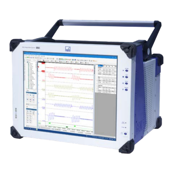
INTRODUCTION Introduction Introducing GEN7iB Welcome! You have made the right choice; your GEN7iB Mobile Data Recorder is one of the most sophisticated and powerful systems on the marketplace and demonstrates the high quality HBM has to offer. GEN7iB is an all-in-one, field-ready, feature-packed unit. Fig. 6.1 Using GEN7iB Some of the main features include: ●... -
Page 67: Mainframe Overview
INTRODUCTION Data archiving is a challenging task when doing data acquisition. GEN7iB offers a variety of storage and archiving options. Internally GEN7iB is equipped with a 960 GB solid state drive. The instrument can be connected to a network using built-in wired interfaces. -
Page 68: Mainframe Feature Comparison
INTRODUCTION 6.2.1 Mainframe feature comparison GEN DAQ Features (1) 1-GEN3i, 1-GEN3iA, 1-GEN7i and 1-GEN7iA/B 1-GEN2tB 1-GEN4tB 1-GEN7tA and 1-GEN17tA 1-GEN7tB and 1-GEN17tB Slots A, B, C only GEN DAQ Features (2) 1-GEN3i, 1-GEN3iA, 1-GEN7i, 1-GEN7iA/B, 1-GEN2tB, 1-GEN4tB, 1-GEN7tA/B and 1-GEN17tA/B GEN7tB INTRODUCTION... -
Page 69: Hardware
INTRODUCTION Hardware The acquisition section of the GEN7iB is based on the successful and proven GEN series Data Acquisition System. In GEN7iB the same concepts are used. Fig. 6.2 Block Diagram GEN7iB Portable Recorder 6.3.1 PCI-e/CPCI backplane GEN7tA/GEN7iB uses a combined PCI-e/CPCI backplane. The PCI-e (Peripheral Compo- nent Interconnect Express) backplane can transfer data at very high speeds to ensure the highest system throughput. -
Page 70: Input Cards
INTRODUCTION Check the detailed specifications of the individual acquisition cards to see whether it uses the fast data storage bus of the GEN7iB if aggregate streaming rates above 200 MB/s are required. 6.3.2 Input cards GEN7iB can accept up to seven input cards. Each input card includes one or more digitizers, a powerful CPU or DSP for filtering, intelligent triggering, and acquisition management. - Page 71 INTRODUCTION Automatic user warnings are initiated using the following diagram (see Fig. 6.3) Fig. 6.3 Thermal protection - Automatic user warnings ● As soon as one of the internal thermocouples measures a temperature above +75 °C for the first time, a single user warning is initiated. As long as the highest temperature measured is above +70 °C and below +80 °C, no additional user warn- ings are initiated.
-
Page 72: Acquisition
INTRODUCTION Acquisition GEN7iB is a multi-channel modular Data Acquisition System. It provides real-time data for waveform and meter displays. It allows unlimited recording duration and file size at a high streaming rate. Statistics are performed in real-time. Its extreme performance signal conditioning includes both Bessel and Butterworth anti-alias filters to provide excellent response. Fig. 6.4 Input channel block diagram It also functions as a transient recorder with a hardware trigger on all channels with hysteresis, delay and logic features. -
Page 73: Statstream
INTRODUCTION 6.4.1 StatStream Most PC-based DAQ systems can easily acquire megabytes of data. But even the most powerful PC is poorly equipped to display and process files of megabytes or gigabytes. In fact, most DAQ systems fail to display over 99% of live data! The exclusive Stat- Stream technology accelerates all aspects of a measurement task with dedicated ®... -
Page 74: Signal Conditioning
INTRODUCTION Signal conditioning GEN7iB supports common analog sensors with the highest performance signal condi- tioning available. All inputs are sampled simultaneously for exact time correlation. Plug-and-play hardware discovery with scalability to any number of channels. Percep- tion software can group and outline similar amplifiers for one-click settings. Extensive diagnostics gives the confidence of correctly wired and working sensors before any test. GEN7tB INTRODUCTION... -
Page 75: Data Storage
INTRODUCTION Data storage In addition to mega samples of on-board RAM, record data directly to the GEN7iB hard drive, or USB device. In addition you can archive your data on a USB stick, or to a network server over the Gigabit Ethernet. GEN7iB always stores to on-board high- speed RAM. Recorded data is then automatically stored at the GEN7iB defined storage location at maximum speed. -
Page 76: Pc Section
INTRODUCTION PC Section GEN7iB has a built-in industrial PC. This PC provides all the standard features that you would expect from an industrial grade quality PC. Features include: ● Intel Core™ i5 processor (6 generation) ® QM170 chipset ● ● Microsoft 64 bit Windows 10 Operating System... -
Page 77: Perception Software
INTRODUCTION Perception Software Perception Software is installed on your GEN7iB for control, analysis, archiving and reporting. Notice For general information on Perception, please refer to user manual for Perception, which is provided separately. 6.8.1 Windows logon password and remote desktop access ®... -
Page 78: Perception Language Settings
INTRODUCTION Perception language settings Various program settings are stored in the Perception preferences. These settings include, but are not limited to, Perception language, start-up options, options for updates, video information, display settings, etc. Fig. 6.6 Preferences dialog To open the Preferences dialog: ●... - Page 79 INTRODUCTION User Interface Language options To startup Perception in a specific User Interface Language: Click Preferences... in the File menu. Select General in the tree view of the Preferences dialog. In the Language drop-down list, you can select from the following choices: Fig. 6.7 User Interface Language area (detail) default: The software detects the operating system language and uses that lan- guage (if available).
-
Page 80: Setting Up The Gen7Ib
SETTING UP THE GEN7iB Setting up the GEN7iB PC connections GEN7iB has a PC motherboard inside. This PC motherboard has a lot of connections that can be used to connect other devices to the GEN7iB system. Fig. 7.1 PC connections I/O connector (trigger in/out, clock in, event in/out, start/stop) See chapter „I/O connector“... - Page 81 SETTING UP THE GEN7iB Digital Event/Timer/Counter See chapter „Digital Event/Timer/Counter“ on page 97. Removable drive bay See chapter „Removable drive bay“ on page 83. GEN7iB SETTING UP THE GEN7iB...
-
Page 82: Usb 3.0 And Usb 2.0 Ports
SETTING UP THE GEN7iB 7.1.1 USB 3.0 and USB 2.0 ports The GEN series integrated system supports both USB2.0 and USB 3.0 ports. USB 3.0 is the third major version of the Universal Serial Bus (USB) standard for com- puter connectivity. Among other improvements, USB 3.0 adds a new transfer mode called "SuperSpeed"... -
Page 83: Removable Drive Bay
SETTING UP THE GEN7iB 7.1.4 Removable drive bay The GEN7iB drive bay supports two different disk options: Removable system Solid State Drive (1-G074) Removable Solid State Drive (1-G075) The removable system Solid State Drive (G074) is a factory installed option. This option consists of two Solid State Drives configured in a RAID 0 volume. RAID volumes require a match between the systems BIOS settings and the configuration of the disk volumes. - Page 84 SETTING UP THE GEN7iB Fig. 7.3 USB-based drive carrier host CAUTION Never use removable disk options that are enabled by RAID together with standard non- RAID disk setups. Also, never mix RAID modes when using removable drives. Your drive bay may no longer be accessible and all data on the RAID bay will be lost.
- Page 85 SETTING UP THE GEN7iB Fig. 7.4 GEN7iB removable drive bay Drive bay Drive carrier Keylock Eject button Inserting a drive carrier: Power off GEN7iB. If the drive bay eject button is released, push it to lock the eject button inside the bay.
- Page 86 SETTING UP THE GEN7iB Drive carrier Safe drive carrier removal: Power off GEN7iB. Insert the key included in delivery into the keylock and turn it 90 degrees counter-clockwise to unlock the drive carrier. Push the eject button below the keylock once to release the button. Push the eject button again to eject the carrier.
-
Page 87: Removing And Installing Input Cards
SETTING UP THE GEN7iB Removing and installing input cards CAUTION HBM uses state-of-the-art electronic components in its equipment. These electronic components can be damaged by discharge of static electricity (ESD). ESD damage is quite easy to induce, often hard to detect, and always costly. Therefore, we must emphasize the importance of ESD preventions when handling a GEN7iB system, its connections or a plug-in card. -
Page 88: Installing Cards
SETTING UP THE GEN7iB Press the inner grey button on each ejector to release the catch. Fig. 7.6 Removing card (Part 2) Press both ejectors outward to release the card. They act as levers to gently pull the card from its backplane sockets Slide the card out of the GEN7iB unit. - Page 89 SETTING UP THE GEN7iB WARNING Screws must be locked to meet CE emissions. Fig. 7.8 Blind panel (1-G009) WARNING Any empty slots must be covered with a blind panel on the back to meet the cooling require- ments of the mainframe. GEN7iB SETTING UP THE GEN7iB...
-
Page 90: Handle
SETTING UP THE GEN7iB Handle The handles are used to carry the GEN7iB system. Only carry the instrument when the handles are in the upright position. Fig. 7.9 GEN7iB with handle in the upright position GEN7iB SETTING UP THE GEN7iB... -
Page 91: Turning The Handle
SETTING UP THE GEN7iB 7.3.1 Turning the handle Put instrument on a flat surface. Push in the button on both sides of the handle. Fig. 7.10 Button on the handle GEN7iB SETTING UP THE GEN7iB... -
Page 92: Feet
SETTING UP THE GEN7iB Feet GEN7iB stands on four rubber feet in normal operation position. Two feet are posi- tioned at the rear and two are at the front of the instrument. Two extra, foldable front feet can be used to lift the instrument. The angle created is about +6 ° in this position. 7.4.1 To turn the feet out: Put the instrument on a flat surface. -
Page 93: Probe Calibration
SETTING UP THE GEN7iB Probe calibration The GEN7iB mainframe is provided with a probe calibration output. This output can be used to calibrate probes used in combination with the Genesis High-speed measure- ment system. The probe calibration output drives a calibration signal with the following characteris- tics: ●... - Page 94 SETTING UP THE GEN7iB Set the trimmer of the probe so that the signal in Perception resembles the input signal. Fig. 7.13 below shows how the signal should look. When the trimmer is positioned incorrectly, undershoot or overshoot is seen in the signal. Fig.
-
Page 95: Dc Power Output
SETTING UP THE GEN7iB DC power output Fig. 7.14 DC power output DC power output The system has a DC power output connector to power additional systems requiring a DC input power. The connection is set up to connect a QuantumX system to the GEN series mainframe directly. - Page 96 SETTING UP THE GEN7iB DC Power Output Fig. 7.15 Connector power out GEN7iB SETTING UP THE GEN7iB...
-
Page 97: Digital Event/Timer/Counter
SETTING UP THE GEN7iB Digital Event/Timer/Counter Fig. 7.16 Digital Event/Timer/Counter Digital Event/Timer/Counter 1 (AB) Digital Event/Timer/Counter 2 (CD) Digital Event/Timer/Counter 3 (EF) The GEN7iB mainframe comes with three Digital Event/Timer/Counter connectors. These connectors are internally connected to Slots A to F of the mainframe. Each Digi- tal Event/Timer/Counter connector is wired to one pair of acquisition Slots;... - Page 98 SETTING UP THE GEN7iB CAUTION Not all GEN series acquisition cards have support for the Digital Event/ Timer/Counter connector. Only the acquisition cards that have support listed in their specification sheet will be able to use this connector. (See „Model overview (Part 2)“ on page 180 for more details).
- Page 99 SETTING UP THE GEN7iB Digital Event/Timer/Counter Fig. 7.18 Logic threshold voltage levels Overvoltage protection ± 30 V DC Timer/Counter Number of channels GN310B/GN311B and Other input cards GN610B/GN611B input cards Four per card Two per card Two cards per connector Two cards per connector Functions See specifications of acquisition cards that support these inputs...
- Page 100 SETTING UP THE GEN7iB Digital Event/Timer/Counter Connector Pin Assignment Fig. 7.19 Pin diagram for Digital Event/Timer/Counter connector Additional Timer/Counter channels are only available if a GN310B/GN311B or GN610B/ GN611B card is installed. GEN7iB SETTING UP THE GEN7iB...
-
Page 101: Isolated Event Adapter
SETTING UP THE GEN7iB 7.7.1 Isolated event adapter Fig. 7.20 Block diagram and image To isolate the Digital Event/Timer/Counter inputs a special adapter is available. It has a maximum 230 V RMS isolation spec and comes with a connection cable to directly connect the adapter to the mainframe. -
Page 102: Torque/Rpm Adapter
SETTING UP THE GEN7iB 7.7.2 Torque/RPM adapter Fig. 7.21 Block diagram and image HBM's Torque and RPM sensors come standard with RS422 digital output signals. As the GEN series Digital Event/Timer/Counter inputs are TTL inputs, signal need to be converted to make both side able to work together. The Torque/RPM adapter is designed to both perform the signal conversion as well as make sure the connectors used support standard Torque and RPM cables. - Page 103 SETTING UP THE GEN7iB Fig. 7.22 Block Diagram Torque/RPM Adapter Using this adapter T12, T40 and alike torque transducer can be directly connected to the GEN series mainframe without additional need to build your own cables. GEN7iB SETTING UP THE GEN7iB...
-
Page 104: Eaxle Setup
SETTING UP THE GEN7iB The adapter also supports a so called T-function. If the need exists to connect the out- put of the Torque/RPM sensor both to a GEN series mainframe and any other receiving system, the T-function output renews the original signal with an RS422 transmit buffer. This setup garantees a point to point connection required for proper RS422 usage. -
Page 105: Accessing The Cpu Section
SETTING UP THE GEN7iB Accessing the CPU section CAUTION HBM uses state-of-the-art electronic components in its equipment. These electronic components can be damaged by discharge of static electricity (ESD). ESD damage is quite easy to induce, often hard to detect, and always costly. Therefore, we must emphasize the importance of ESD preventions when handling a GEN7iB system, its connections or a plug-in card. - Page 106 SETTING UP THE GEN7iB Remove the plugs from the rubber back bumpers. Then remove the rubber bum- pers. Also remove the two indicated screws (see Figure Fig. 7.23). Fig. 7.23 Remove bumpers Screws GEN7iB SETTING UP THE GEN7iB...
- Page 107 SETTING UP THE GEN7iB Remove the blue plastic cover. Fig. 7.24 Remove top panel on back GEN7iB SETTING UP THE GEN7iB...
- Page 108 SETTING UP THE GEN7iB Remove all indicated screws from the GEN7iB. Fig. 7.25 Remove side/top screws GEN7iB SETTING UP THE GEN7iB...
- Page 109 SETTING UP THE GEN7iB Remove the cover of the GEN7iB. Fig. 7.26 Lift cover plate Access the CPU section, e.g. for BIOS battery replacement or removal. For more information about battery replacement, please refer to chapter „Removal and replacement“ on page 55. Close the GEN7iB CPU section in reversed order.
-
Page 110: Air Filter Replacement
SETTING UP THE GEN7iB Air filter replacement CAUTION HBM uses state-of-the-art electronic components in its equipment. These electronic components can be damaged by discharge of static electricity (ESD). ESD damage is quite easy to induce, often hard to detect, and always costly. Therefore, we must emphasize the importance of ESD preventions when handling a GEN7iB system, its connections or a plug-in card. - Page 111 SETTING UP THE GEN7iB Remove the air filter locking bracket. The air filter can be removed from the GEN7iB. The filter can be easily removed if the GEN7iB is placed slightly over the edge of a table. Fig. 7.28 Remove air filter Insert the air filter and close the GEN7iB in reverse order. GEN7iB SETTING UP THE GEN7iB...
-
Page 112: Getting Started
GETTING STARTED Getting Started Front panel control Standby On GEN7iB, the standby button is located on the front panel. When this button is pressed, the instrument state toggles between operating and standby mode. In standby mode, some power is consumed and the instrument is NOT disconnected from the AC supply. - Page 113 GETTING STARTED Fig. 8.2 Acquisition control - Detail Record Stop Pause Trigger USB ports Two USB 2.0 ports are located on the front and in the bottom left-hand corner of the unit for easy access. The remaining USB ports are located on the back of the unit. Fig.
-
Page 114: Getting Started
GETTING STARTED Getting started When GEN7iB is started up for the first time, the software starts and connects to the integrated GEN7iB data acquisition unit automatically. Each time you power off the system, the changes made to the preferences and set- tings are saved automatically. These settings are then loaded the next time you power on GEN7iB. -
Page 115: Acquisition And Storage
ACQUISITION AND STORAGE Acquisition and Storage Introduction From Perception V7 to V8, significant work was done on the acquisition modes: ● The User Interface was improved: everything related to acquisition modes was brought together in a single interface element ● New acquisition modes were added ● Some new terminology was introduced The "Acquisition and Storage" section explains the Acquisition Modes in Perception V8 and, where required, compares them with Perception V7. - Page 116 ACQUISITION AND STORAGE Groups Fig. 9.1 Example of assigning a recorder to a group General area Settings Sheet Recorder column Groups column Editable cell for Groups A measurement setup may consist of several Recorders (C) or Acquisition Cards dis- tributed over one or more mainframes. Perception recorders or acquisition cards can be collected in Groups (D).
- Page 117 ACQUISITION AND STORAGE Sweeps Fig. 9.2 Sweep combined with a continuous recording Perception has the powerful possibility to record certain parts of the recording at a dif- ferent sample rate. Certain intervals of the recording (called sweeps) are recorded at a high sample rate whereas the continuous parts are recorded at a reduced sample rate.
- Page 118 ACQUISITION AND STORAGE Triggers The moment in time where a Sweep interval occurs is determined by Triggers, and the length of a sweep by user specification and possibly by triggers as well. Triggers are caused by user-defined events such as the level crossing of a signal, result of a calcu- lation crossing a level, a rising edge of an external signal, etc. Examples of different types of sweeps are shown below: Fig.
-
Page 119: Terminology
ACQUISITION AND STORAGE 9.1.2 Terminology Perception has very fast drive access. In many cases, the digital recorded data can immediately be stored on the drive. However, in some cases (e.g., many channels at a very high sample rate) even the fastest drives cannot keep up. In such a case, the user can choose to store sweep data first to very fast dedicated trigger memory. The terminology is “to trigger memory first”. -
Page 120: Acquistion Modes - User Interface
ACQUISITION AND STORAGE Acquistion Modes - User Interface Perception V8 Acquisition Modes An overview of the Perception V8 Acquisition Modes User Interface is shown in Fig. 9.6. It consists of the following areas: Fig. 9.6 Overview of the Perception 8 Acquisition Modes User Interface Diagram of what is recorded and when (see Fig. - Page 121 ACQUISITION AND STORAGE Choose the type of Acquisition Mode (see Fig. 9.8) Fig. 9.8 Start of data recording to drive Specify the pre- and post-trigger times (in case triggers are used) (see Fig. 9.9) Fig. 9.9 Pre- and post-trigger duration High sample rate and the reduced sample rate per group can be defined. In this area it should also be indicated which data is to be stored (see Fig.
- Page 122 ACQUISITION AND STORAGE Define how a recording or sweep should be stopped (see Fig. 9.11) Fig. 9.11 Stop of data recording Define how the total data acquisition process should be stopped (see Fig. 9.12) Fig. 9.12 Stop acquisition Further detailed trigger settings (see Fig. 9.13) Fig. 9.13 Trigger Name of the recording file and where it is stored (see Fig. 9.14) Fig. 9.14 Recording file settings GEN7iB ACQUISITION AND STORAGE...
-
Page 123: Setup For The Acquisition Modes
ACQUISITION AND STORAGE Setup for the Acquisition Modes ● On start of acquisition (on page 123) ● Wait for trigger (on page 125) ● Wait for trigger to trigger memory first (on page 127) ● On start of acquisition reduced rate and wait for trigger to trigger memory first (on page 130) 9.3.1 On start of acquisition Fig. 9.15 Acquisition mode: On start of acquisition In Start of data recording to drive area, select the On start of acquisition check box (see Fig. - Page 124 ACQUISITION AND STORAGE In the Stop of data recording area, select the On stop acquisition checkbox (see Fig. 9.17). A continuous recording directly to a drive, from the start to the end of the acquisi- tion time. Neither triggers are required nor used. Fig.
-
Page 125: Wait For Trigger
ACQUISITION AND STORAGE 9.3.2 Wait for trigger Fig. 9.19 Acquisition mode: Wait for trigger In Start of data recording to drive area, select the Wait for trigger check box (see Fig. 9.20) Fig. 9.20 Start of data recording to drive GEN7iB ACQUISITION AND STORAGE... - Page 126 ACQUISITION AND STORAGE In the Stop of data recording area, select the On end of post-trigger check box (see Fig. 9.21) The recording stops after the post-trigger time has elapsed. A single sweep record- ing directly to a drive, based on a single trigger. Fig.
-
Page 127: Wait For Trigger To Trigger Memory First
ACQUISITION AND STORAGE 9.3.3 Wait for trigger to trigger memory first Fig. 9.23 Acquisition mode: Wait for trigger to trigger memory first In Start of data recording to drive area, select the Wait for trigger to memory first check box (see Fig. 9.24) Fig. 9.24 Start of data recording to drive GEN7iB ACQUISITION AND STORAGE... - Page 128 ACQUISITION AND STORAGE A recording with multiple sweeps (in this case 5 triggers specified), first recorded to (very fast) trigger memory and after that collected in a PNRF file on a drive (see Fig. 9.25). Fig. 9.25 Stop acquisition In the Stop of data recording area, select the On end of post-trigger / Every trigger checkboxes (see Fig. 9.26). In this case, the selection was made to (re-)start the post-trigger time at every trigger.
- Page 129 ACQUISITION AND STORAGE Data for Group1 is recorded at 200 kS/s and stored, for Group 2 at 5 kS/s and also stored (see Fig. 9.28) Fig. 9.28 Storage and timebase GEN7iB ACQUISITION AND STORAGE...
-
Page 130: On Start Of Acquisition Reduced Rate And Wait For Trigger To Trigger Memory First
ACQUISITION AND STORAGE 9.3.4 On start of acquisition reduced rate and wait for trigger to trigger memory first Fig. 9.29 Acquisition mode: On start of acquisition and wait for trigger to trigger memory first In Start of data recording to drive area, select the On start of acquisition reduced rate and wait for trigger to trigger memory first check box (see Fig. 9.30). Fig. - Page 131 ACQUISITION AND STORAGE A recording with multiple sweeps (in this case 5 triggers specified), first recorded to (very fast) trigger memory and after that collected in a PNRF file on a drive (see Fig. 9.31). Fig. 9.31 Stop acquisition The recording is combined with a continuous recording, everything stored in a single PNRF file (see Fig. 9.32). Fig. 9.32 On start of acquisition and wait for trigger to trigger memory first - diagram The data is recorded and stored with the following values: ●...
-
Page 132: Digital Trigger Modes
DIGITAL TRIGGER MODES Digital Trigger Modes 10.1 Introduction Within the GEN7iB data acquisition system, every channel is equipped with a trigger detector, which makes it possible to record just the phenomenon of interest, instead of having to search the full memory to find it. The trigger detector gives the system the power to capture elusive, short and unpredictable events. It determines how easily the event of interest can be extracted. -
Page 133: Understanding Digital Triggering
DIGITAL TRIGGER MODES 10.2 Understanding digital triggering Technically speaking, there are two approaches to determine the known, predefined situation of the signal: analog or digital. Each channel in the GEN series system is equipped with a digital trigger detector. Digi- tal triggering has the benefit of stable vertical reference levels, no horizontal jitter, and not depending on signal frequency. A disadvantage of a digital trigger detector is its inability to detect events that occur between two consecutive samples. -
Page 134: Valid Trigger Conditions
DIGITAL TRIGGER MODES For the advanced trigger modes, the single-level trigger detector with programmable hysteresis has been implemented twice to provide a dual-level trigger detector. Levels are usually referenced as primary trigger level and secondary trigger level. 10.2.2 Valid trigger conditions Trigger detection is based on level crossing. A signal has to cross a specified level to be considered a trigger condition. - Page 135 DIGITAL TRIGGER MODES Fig. 10.3 shows the influence of the additional hysteresis. Fundamentally, everything is the same as described earlier. The only difference now is that a second level (H) is used to “arm” the level trigger detector. Otherwise stated, the trigger level has been expanded to be a trigger zone that spans multiple levels. Fig.
-
Page 136: Trigger Modes
DIGITAL TRIGGER MODES 10.3 Trigger modes Using the various trigger modes, GEN7iB data acquisition system is expanded to an extremely versatile transient recorder. The trigger circuits may be configured to trigger on many types of phenomena. In this section, the different trigger modes and their extensions are discussed in detail. 10.3.1 Basic trigger mode The basic trigger mode can be compared to the trigger mode available when using an analog trigger detector, for example as found on a classic scope. -
Page 137: Dual Trigger Mode
DIGITAL TRIGGER MODES 10.3.2 Dual trigger mode In dual trigger mode two detectors are active and working simultaneously: the primary level P and the secondary level S. With two levels, it is possible to define a range that the input signal must be within. As soon as the signal becomes larger than the upper level or smaller than the lower level, the detector generates a trigger. -
Page 138: Trigger Qualifier
DIGITAL TRIGGER MODES 10.3.3 Trigger qualifier The trigger detectors of a channel can also be used as qualifiers. A trigger qualifier is a situation that enables (arms) the recorder trigger features. The recorder trigger features are a combination of various channel, external, between-recorders and other trigger options. There are two qualifier modes: ● Basic single-level qualifier. The level detector operates identical to „10.3.1 Basic trigger mode“ on page 136. ●... -
Page 139: Recorder And System Trigger
DIGITAL TRIGGER MODES 10.4 Recorder and system trigger The trigger modes and features described so far are channel-based. Each analog chan- nel within a GEN series system has a digital trigger detector. The trigger signals of all channels of a single recorder are combined through a logical OR to generate a com- bined trigger. This trigger can be combined with an external trigger and qualifiers. The final result is a recorder trigger. The triggers that are generated by individual recorders can be distributed to other recorders and mainframes. -
Page 140: Channel Alarm
DIGITAL TRIGGER MODES 10.5 Channel alarm Each channel has the capability to generate an alarm. An alarm situation is detected with a basic dual level detector. There are two alarm modes: ● Basic single-level alarm. The alarm line is active for as long as the signal exceeds the level in the specified direction. For more information on the level comparator, please refer to „10.3.1 Basic trigger mode“... -
Page 141: Interface/Controller
INTERFACE/CONTROLLER Interface/Controller 11.1 Introduction The Interface/Controller uses a high-end CPU with an embedded operating system. It is used to communicate with controlling computers and supports extra storage options. Each complete mainframe houses an Interface/Controller, which enables data input and output so that the mainframes can be connected. Fig. -
Page 142: Communication And Control
INTERFACE/CONTROLLER 11.2 Communication and control The GEN series uses standard TCP/IP protocol over Ethernet to communicate with the PC. The Interface/Controller provides access to the Ethernet network. Fig. 11.2 Ethernet LED indicators Link speed RJ45 network Activity LED RJ45 network Activity LED optical network Link speed LED optical network Ethernet LED indicators... -
Page 143: Network Protocols And Ports
INTERFACE/CONTROLLER 11.2.1 Network protocols and ports All tethered GEN DAQ series mainframes use Ethernet protocols to communicate with the controlling PC. The following table gives an overview of the used protocols, ports, packet sizes and frequency of use on the network. General TCP/IP IPv4 with standard Ethernet V2 fames (MTU = 1500 bytes) is used. -
Page 144: Using The 1 Gbit Option Connections
INTERFACE/CONTROLLER 11.2.2 Using the 1 Gbit option connections LC Connection Using the SFP + Option LC optical connections that need an SFP device to enable their use with a LC con- nected optical cable. The GEN series mainframes come with an optional 1 Gbit optical network support in the form of an SFP module. -
Page 145: Master/Sync Connector
INTERFACE/CONTROLLER 11.3 Master/Sync connector The GEN7iB Master/Sync connector supports both standard (compatible with legacy mainframes) and extended synchronization. Fig. 11.3 Interface/Controller Master/Sync connector (optical) Standard Synchronization: Synchronizes the first sample in the recording for each mainframe, prevents frequency drift of the sample rates within each mainframe, synchronously exchanges every channel trigger connected to the Master/Sync trigger bus to/from each connected mainframe and automatically compensates for the cable length delay. - Page 146 INTERFACE/CONTROLLER The Master/Sync connector supports (please refer to chapters „Connecting the Mas- ter/Sync connector“ on page 149 and „Connecting multiple mainframes using the Master/Sync card“ on page 150 for wiring details): ● Directly connect to one mainframe using the Master/Sync connector. Each main- frame can then be Master or Sync mainframe.
- Page 147 INTERFACE/CONTROLLER Master/Sync connector operating modes The Master/Sync connector has three operating modes: ● Master ● Sync ● Stand-alone In stand-alone mode, the Master/Sync connector is not used. Cables can be left attached, as no information is exchanged. Fiber optic cable The Master/Sync connection uses an optical duplex cable with LC connectors that connects two Master/Sync connectors.
- Page 148 INTERFACE/CONTROLLER LED indicators On the front panel of the Master/Sync connector, two LEDs indicate the status of the link. ● icon is used to identify the signal detect function. ● The icon is for data/synchronization identification. Signal detection Data/synchronization identification The following table shows the function and possible combinations of the two LEDs. FRONT PANEL LED INDICATORS Status Description...
-
Page 149: Connecting The Master/Sync Connector
INTERFACE/CONTROLLER 11.3.1 Connecting the Master/Sync connector With the fiber optic cable, connect the Master/Sync connector of two mainframes. In this setup, one mainframe must be set to Master while the other mainframe must then be set to Sync mainframe. In this setup, extended synchronization is used auto- matically. Fig. 11.5 Connecting the Master/Sync Master mainframe Sync mainframe Fiber optic cable... -
Page 150: Connecting Multiple Mainframes Using The Master/Sync Card
INTERFACE/CONTROLLER 11.3.2 Connecting multiple mainframes using the Master/Sync card The multiple mainframe Master/Sync setup only works in a star configuration. All Mas- ter/Sync fiber optic cables are on one side connected to the Master mainframe while the other side connects to one Sync mainframe. The master mainframe needs to be extended with one or more optional option carrier cards (G081). Each option carrier card can be extended with one or two Master output cards (G083). - Page 151 INTERFACE/CONTROLLER Fig. 11.6 Master/Sync configuration with five sync mainframes Master mainframe Sync mainframe Fiber optic cable Connect one of the connectors of the Master Output Card(s) (G083) to the Master/ Sync connector of the Sync mainframe. Connect one of the connectors of the Master Output Card(s) (G083) to the Master/ Sync connector of the second Sync mainframe.
-
Page 152: Setting The Master/Sync Operating Modes
INTERFACE/CONTROLLER 11.3.3 Setting the Master/Sync operating modes Each mainframe can be used as a Master or Sync mainframe. The operating modes are set up using the Perception software. In the Perception work area: Fig. 11.7 Perception work area with Master/Sync Settings tab General group Master/Sync mode column... - Page 153 INTERFACE/CONTROLLER To disable the Master/Sync operation and set the mainframe to Stand-alone mode: Select the mainframe(s) that should be used as Stand-alone. Double-click on the Master/Sync mode cell to open it for modification. In the drop-down list that appears, select Stand-alone. Cables do not have to be removed, as the mainframe does not use the connected cable during stand-alone mode.
-
Page 154: Synchronizing A Master/Sync Setup To External Time Sources
INTERFACE/CONTROLLER 11.3.4 Synchronizing a Master/Sync setup to external time sources In a Master/Sync setup, all time information is recorded by the Master mainframe only. Synchronization source selection on Sync mainframes is disabled as Sync mainframes are dedicated to follow the Master mainframe. For the Master mainframe, the date and time are controlled by either the PC (RTC), PTP master, IRIG or GPS, depending on the synchronization source selected. -
Page 155: I/O Connector
INTERFACE/CONTROLLER 11.4 I/O connector Fig. 11.9 Interface/Controller I/O connector (trigger in/out, clock in, event in/out, start/stop) The I/O connector comes with a BNC breakout cable for direct BNC cable connection to each function (see Fig. 11.10) Fig. 11.10 BNC breakout cable GEN7iB INTERFACE/CONTROLLER... -
Page 156: I/O Connector Input Overvoltage Protection
INTERFACE/CONTROLLER 11.4.1 I/O connector input overvoltage protection All inputs of the I/O connector are over voltage protected. All inputs use the following schematic approach. Fig. 11.11 I/O connector schematic inputs Due to the 20 kΩ pull-up resistor all inputs will be “TTL High” and only need an external short to signal ground to be operated. The 2 kΩ series resistor together with the diode clamps to ground and +5 V protect the digital circuitry up to the specified voltages. The clamping diodes and other parasitic capacitors do create a capacitive load on your signal source and limit the signal bandwidth. -
Page 157: I/O Connector Functions And Connector Pinning
INTERFACE/CONTROLLER 11.4.2 I/O connector functions and connector pinning External Event In This input is software selectable between External Cycle Event In and Trigger Arm. External Cycle Event In can be used in RT-FDB context as cycle source. Trigger Arm can be used to arm triggers within in the mainframe. For more information about External Event In and RT-FDB usage, please refer to chapter „External Event In use with RT-FDB“... - Page 158 INTERFACE/CONTROLLER External Trigger In/Out This input and output are related to the recorder trigger logic. For more informa- tion, please refer to „Recorder and system trigger“ on page 139. External Start In/External Stop Int For more information about External Start In/External Stop In, please refer to chapter „External Event In use with RT-FDB“...
-
Page 159: External Start In/External Stop In
INTERFACE/CONTROLLER 11.4.3 External Start In/External Stop In The External start/stop (see Fig. 11.12) settings are located in the General/Mainframe setting page of the settings spreadsheet. The settings are only visible when Advanced (All settings) is enabled (see Fig. 11.13). Fig. 11.12 General/Mainframe settings External start/stop mode columns To enable the advanced settings, right click on the table header (see Fig. - Page 160 INTERFACE/CONTROLLER The External stopmode setting can be used to configure the external stop input. When selecting Disabled, the signal on the input is ignored. When selecting Rising Edge, a stop is initiated when a rising edge is detected. When selecting Falling Edge, a stop is initiated when a falling edge is detected. The minimum pulse width for both External Start In and External Stop In is 500 ns.
-
Page 161: External Event In Use With Rt-Fdb
INTERFACE/CONTROLLER 11.4.4 External Event In use with RT-FDB The External Event In signal can be used as TTL input in RT-FDB. This signal can be used in the RT-FDB External Cycle Event In function. High frequent noise on the TTL input can be filtered using a debounce filter. The use of the debounce filter delays the signal before an event can be derived. This delay can only be compensated to filter settings up to 2 μs, see table below. -
Page 162: Option - Removable Solid State Drive (Ssd)
INTERFACE/CONTROLLER 11.5 Option - Removable Solid State Drive (SSD) The GEN7iB has a removable Solid State Drive bay built-in. Fig. 11.14 Solid State Drives (SSD) No disk repair and/or data recovery tools exist. Do not attach the disk to a Windows ®... - Page 163 INTERFACE/CONTROLLER For specifications and ordering information, please refer to the GEN7iB Data Sheet. Verification To verify that Local Storage is enabled: Connect to the mainframe Navigate to the Settings tab; Mainframe Disk 1 must be visible: Fig. 11.15 Storage location with Mainframe Disk 1 enabled Storage location option GEN7iB INTERFACE/CONTROLLER...
-
Page 164: Option - Optical 1 Gbit Ethernet Interface
INTERFACE/CONTROLLER 11.6 Option - Optical 1 Gbit Ethernet interface The Interface/Controller supports an optical 1 Gbit Ethernet interface by means of an SFP module. An SFP module is a small, form-factor and pluggable transceiver that supports direct optical network connections. WARNING Laser Safety The system is classified as a Class 1 laser product. - Page 165 INTERFACE/CONTROLLER Selecting cables and cable lengths: Cables need to have different properties when they exceed certain lengths. These cable properties are based on the properties of light in an optical fiber. Single Mode The cable is a type of cable that has a relatively small light-car- rying core. Light in a small core makes fewer internal reflections so that the path of light is close to a straight line. Therefore, the light can travel further distances.
-
Page 166: Option - 10 Gbit Ethernet Interface (Sfp+ Module)
INTERFACE/CONTROLLER 11.7 Option - 10 Gbit Ethernet interface (SFP+ Module) The 10 Gbit Ethernet option is a Factory installed, ready to use Ethernet option with two available Ethernet interfaces. The 10 Gbit Ethernet card can be installed in addition to the standard on-board 1 Gbit Ethernet connection. - Page 167 INTERFACE/CONTROLLER Connections and using the 10 Gbit Option A 10Gbit LC Connection Using the SFP+ Option 10Gbit LC optical connec- tions need an SFP+ module to enable their use with LC connected optical cable. A 10Gbit RJ45 Connection Using the SFP+ Option 10Gbit RJ45 copper connec- tions need an SFP+ module to enable their use with RJ45...
- Page 168 INTERFACE/CONTROLLER Front panel layout The front panel of the10 Gbit Ethernet option has the following layout: Fig. 11.18 Front panel of XMC401 10 Gbit Ethernet card CH B = NIC2 (Requires SFP+ module, not shown) ACT (green): Ethernet Activity (on when active) LNK (green): Ethernet Link (on when active) 10 Gbit (green): Ethernet Speed 10 Gigabit (always on) 1 Gbit (green): Ethernet Speed 1 Gigabit (always on...
- Page 169 INTERFACE/CONTROLLER 10 Gbit Ethernet Option accessories The 10 Gbit Ethernet card supports multiple (10 Gbit) SFP+ modules which are sepa- rately available, see options in the GEN7iB data sheet for ordering. The types of 10 Gbit SFP+ module that are used with this Ethernet card are: ●...
- Page 170 INTERFACE/CONTROLLER Cable selection and lengths: Cables require different properties when they exceed certain lengths based on the properties of light in an optical fiber. Single Mode Cable is a type of cable that has a relatively small light carrying core and therefore makes fewer internal reflections so that the path of light is closer to a straight line and thus can travel further distances.
- Page 171 INTERFACE/CONTROLLER Fig. 11.20 Basic setup - 10 Gbit Ethernet to PC Connecting the 10 Gbit Ethernet Option to a PC To be able to use this option you also need the correct connection or interface attached to your PC. The correct connection is not always an SFP+ module but there must be a network card or adaptor installed that supports the same specifications as the SFP+ modules used on the GENDAQ side.
- Page 172 INTERFACE/CONTROLLER Network Interface selection in Perception With the 10 Gbit Ethernet option installed and ready to go you will be provided with the two following interfaces for selection: ● Optical 10 Gbit NIC1 ● Optical 10 Gbit NIC2 In Perception these interfaces are available in the Settings menu > Mainframe Network Setup see Fig.
-
Page 173: Installing A 1 Gbit Sfp/10 Gbit Sfp+ Module
INTERFACE/CONTROLLER Windows - optimum settings ® Important To best achieve data transfer rates greater than 200 MB/s please make sure the following settings are introduced to your network adaptor via the settings in Windows ® Windows® 10G network adapter settings: ●... - Page 174 INTERFACE/CONTROLLER Warnings Before installing this device, please read and make sure that you have understood the following warnings, which are specific for this device. Description of Electrostatic Discharge (ESD) CAUTION Electrostatic discharge (ESD) can cause damage to electronic devices if discharged into the device. Take steps to avoid such an occurrence. CAUTION HBM uses state-of-the-art electronic components in its equipment.
- Page 175 INTERFACE/CONTROLLER Installation steps First, make sure that the mainframe unit is switched off. Then locate the available SFP slot and remove the plastic plug (if inserted). Fig. 11.23 Interface/Controller SFP location Interface/Controller SFP location Remove cap GEN7iB INTERFACE/CONTROLLER...
- Page 176 INTERFACE/CONTROLLER Grasp the module between fingers and thumb at the end with the small black removal bar. Push the back end into the available SFP slot, until you hear a click. Fig. 11.24 Insert device in SFP slot Insert device GEN7iB INTERFACE/CONTROLLER...
- Page 177 INTERFACE/CONTROLLER Embedded software detects the device and automatically connects to it when the mainframe is powered on. Fig. 11.25 SFP slot with device Device being inserted GEN7iB INTERFACE/CONTROLLER...
-
Page 178: Removing A 1 Gbit Sfp/10 Gbit Sfp+ Module
INTERFACE/CONTROLLER 11.7.2 Removing a 1 Gbit SFP/10 Gbit SFP+ Module To remove the module from the mainframe, first make sure that the mainframe is powered off. Then grasp the small black removal bar and pull it away and out from the mainframe. The spring-loaded removal bar releases the SFP from the front panel. Fig. -
Page 179: Input Cards
INPUT CARDS Input Cards 12.1 Available input cards Model overview (Part 1) GEN series cards Model GN310B GN311B 200 k GN610B GN611B 200 k GN815 GN816 200 k GN840B 500 k GN1640B 500 k GN1202B 100 M GN8101B 250 M GN8102B 100 M GN8103B... - Page 180 INPUT CARDS Model overview (Part 2) GEN series cards Model GN310B 2 GB GN311B 200 k 2 GB GN610B 2 GB GN611B 200 k 2 GB GN815 2 GB GN816 200 k 200 MB GN840B 500 k 2 GB GN1640B 500 k 2 GB GN1202B...
- Page 181 INPUT CARDS Optical Fiber Transmitter Channels Transmitter Every transmitter is a single channel unit. Every unit has an unbalanced differential input, ampli- fier, analog anti-alias filter and ADC with an optical data and control link to the receiver card. The receiver card has the recording logic, sample rate selection and memory. Model Receiver card Power Sample rate Resolution Isolation GN110...
-
Page 182: Gn310B (2 Ms/S), Gn311B (200Ks/S) Power Analyzer Input Cards
INPUT CARDS 12.2 GN310B (2 MS/s), GN311B (200kS/s) Power Analyzer input cards ● Accuracy 0.015% of reading, 0.02% of range ● 3 power channels (U and I) ● 5 voltage ranges up to ± 1500 V DC CAT III ● 7 current ranges up to ±... -
Page 183: Measuring Voltages
INPUT CARDS 12.2.1 Measuring voltages Important High bandwidth and measurement cabling. Due to the high bandwidth measurement capabilities of the acquisition card, combined with the high measurement sensitivity of the card, it is important to pay close attention to the measurement cabling. - Page 184 INPUT CARDS HBM KAB2139 cables are designed to meet this setup: Fig. 12.2 Three wire shielded cable setup More KAB2139 details can be found in the GN310B/GN311B data sheet specifications. ● For high frequency disturbances where high bandwidth measurement is not required, the measurement bandwidth can be reduced by using the lowpass filter of the acquisition card. ● If unshielded cables are used, keep them as close together as possible, i.e. posi- tion them next to each other (to keep the loop small).
- Page 185 INPUT CARDS DANGER DANGER Overvoltage and current protection All voltage inputs are protected against voltage overload and current inputs against current overload. This is specified for the high voltage channels at ± 2 kV DC. ● Current inputs 2.5 A peak for all current ranges. ● Low voltage inputs 60 V peak for all ranges. Exceeding these limits, particularly when connected to potentially high-current sources, can cause severe damage that is not covered by the manufacturer's warranty.
- Page 186 INPUT CARDS DANGER DANGER Connectors and cables Connectors to be used Rating Connectors Example ≤ 60 V DC, ≤ 30 V RMS Not recom- mended by ≤ 1000 V CAT IV, KAB2139 ≤ 1500 V DC CAT III GEN7iB INPUT CARDS...
-
Page 187: Connecting 3-Phase Artificial Star Adapter
INPUT CARDS 12.2.2 Connecting 3-phase Artificial Star Adapter Fig. 12.3 Artificial Star Adapter connections procedure (1) Fig. 12.4 Artificial Star Adapter connections procedure (2) GEN7iB INPUT CARDS... - Page 188 INPUT CARDS A typical setup could look like this: Fig. 12.5 GN310B/GN311B Power card connection GEN7iB INPUT CARDS...
-
Page 189: Measuring Currents
INPUT CARDS 12.2.3 Measuring currents The GN310B/GN311B card offers 3 current channels using a 4-pin LEMO connector. The current channels offer two ways of measuring current: Current as current input to two built-in shunt resistors. Typically used for current transducer measurements. Current as voltage input. - Page 190 INPUT CARDS GN310B/GN311B Current Connector and Pinnings GN310B/GN311B front panel LEMO EPG.1B.304.HLN connector Mating connector LEMO FGG.1B.304.GLAD52 (Check cable collet selection details)* Fig. 12.7 FGG.1B.304.GLAD52 mating LEMO connector Ø Fig. 12.8 Cable collet setup * Cable collet selection: Minimum cable diameter Maximum cable diameter ØB ØB...
- Page 191 INPUT CARDS GN310B/GN311B: Current Channel: Voltage mode and cabling Fig. 12.10 Current channel: Voltage mode block diagram (1-KAB2137-2) Fig. 12.11 Recommended Voltage mode connection (1-KAB2137-2) Fig. 12.12 Alternative Voltage mode connection (1-KAB2136-1) GEN7iB INPUT CARDS...
- Page 192 INPUT CARDS GN310B/GN311B: Current Channel: Current mode and cabling Fig. 12.13 Current channel: Current mode block diagram (1-KAB2136-1) Fig. 12.14 Recommended Current mode connection (1-KAB2136-1) GEN7iB INPUT CARDS...
-
Page 193: Connecting Hbm Current Transducers
INPUT CARDS 12.2.4 Connecting HBM current transducers To connect HBM current transducers (1-CTSxxxID) and the interface unit (1-CTPSIU-6-1U) to the GN310B/GN311B card you need the following cables. ● 1-KAB2134-2 GN31XB-CTPSIU 2M LEMO-XLR CURRENT cable ● 1-KAB2133-xx CURRENT TRANSDUCER POWER SUPPLY cable Use these cables according the diagram below to connect all parts together. -
Page 194: Connecting Lem Current Transducers
INPUT CARDS 12.2.5 Connecting LEM current transducers To connect LEM current transducers and the interface unit to the GN310B/GN311B card you need the following cables. ● 1-KAB2136-1 GN31XB 1M LEMO-BANANA VOLT&CURRENT cable ● 11-KAB2133-xx CURRENT TRANSDUCER POWER SUPPLY cable Use these cable according the diagram below to connect all parts together. Fig. -
Page 195: Understanding The Gn310B/Gn311B Category Rating
INPUT CARDS 12.2.6 Understanding the GN310B/GN311B category rating Safety according to the harmonized standard Fig. 12.17 Category indication in accordance with IEC 61010-2-030:2017 Example: A measurement device is specified as 1000 V CAT IV, maximum input to chassis voltage 1000 V CAT III. Basic insulation test voltages in accordance with IEC 61010-2-030:2017 Nominal voltage IEC 61010-2-030:2017 BASIC insulation [V RMS or V DC] 5 sec. - Page 196 INPUT CARDS Reinforced insulation test voltages in accordance with IEC 61010-2-030:2017 Nominal voltage line-to-neutral IEC 61010-2-030:2017 Reinforced insulation AC RMS or DC of being 5 sec. AC test [V RMS] MAINS measured CAT II CAT III CAT IV ≤ 150 2.700 2.210 3.510 > 150 ≤ 300...
-
Page 197: Understanding The Gn310B/Gn311B High Voltage Input
INPUT CARDS 12.2.7 Understanding the GN310B/GN311B high voltage input The high voltage signal input channels of the GN310B/GN311B are of the balanced type. This means that both inputs within one channel pair are exactly the same. The only difference is an opposite polarity or sign. A (simplified) schematic representation of the input channel can be found below (see Fig. 12.18) The input channels are of the isolated type. -
Page 198: Gn310B/Gn311B Isolation Voltage Channel
INPUT CARDS 12.2.8 GN310B/GN311B Isolation Voltage channel An overview of the GN310B/GN311B card isolation and input is shown in the figures below. The isolation within a voltage channel is qualified as 1500 V DC and 1000 V CAT IV basic. The insulation of the voltage channel to chassis is qualified as 1000 V CAT III and 600 V CAT IV reinforced or double. If one voltage channel has its common mode at +1000 V and one at -1000 V (with respect to chassis), the voltage between the two channels is 2000 V. The standards at which the card is certified is IEC61010-1:2010 and IEC61010-2-030:2010. - Page 199 INPUT CARDS ● The insulation between the voltage channel and chassis is classified as REINFORCED or DOUBLE. This can be seen as double insulation, which is neces- sary because the chassis might be accessible (conductive parts can be touched) to users (personal safety). ● Insulation within a voltage channel is BASIC, since a channel is not accessible. Therefore, there is no direct risk to users (product safety).
- Page 200 INPUT CARDS Fig. 12.21 Environment with CAT II and CAT III Fig. 12.22 Environment with CAT IV GEN7iB INPUT CARDS...
- Page 201 INPUT CARDS Voltage Channel - Safe and unsafe connections In the following figures is shown how a GN310B/GN311B power card has to be connected. Safe connection (see Fig. 12.23), unsafe connections (see Fig. 12.24 and Fig. 12.25). WARNING Make sure the cable connectors are put COMPLETELY into the input of the GN310B/ GN311B power card. Fig.
- Page 202 INPUT CARDS WARNING A differential pair can be recognized by the black box around it. Fig. 12.25 GN310B/GN311B Power card - unsafe connection (2) GEN7iB INPUT CARDS...
-
Page 203: Gn310B/Gn311B Isolation Current Channel
INPUT CARDS 12.2.9 GN310B/GN311B Isolation Current channel The specified ± 20 V DC voltage range of the Current channel inputs in voltage mode is such that it falls below the low voltage limit as specified in IEC61010-1. The isolation of the Current channel inputs is in line with the limit for safe voltage and currents as mentioned above. Current Channels Isolation IEC 61010-2-030:2017 Fig. 12.26 Current channels isolation ratings Current Channels Isolation Input pin to chassis ±... -
Page 204: Gn310B/Gn311B Type Testing Of The Hv Channels
INPUT CARDS 12.2.10 GN310B/GN311B type testing of the HV channels Channel to chassis voltages (and test voltages) To qualify the insulation as 1000 V CAT III and 600 V CAT IV, certain tests are per- formed on some cards during the engineering design qualification phase. These tests are known as type tests. These tests are described in the IEC61010-1:2010 and IEC61010-2-030:2010 standards. - Page 205 INPUT CARDS Within high voltage channel isolation test (harmonized standard) For the channel input test, the AC tests below (see Fig. 12.28) is used. The test value meets the requirements for 1000 V CAT IV BASIC. Tests are conducted for 5 seconds and one minute.
- Page 206 INPUT CARDS High potential test The type tests are performed on a selection of cards to test the design. Every card produced undergoes a production test to verify that the card has been produced cor- rectly and that the card is safe. The tests are called “hipot” (high potential) tests (see Fig.
- Page 207 INPUT CARDS Fig. 12.30 Hipot testing Channel 2 GEN7iB INPUT CARDS...
- Page 208 INPUT CARDS Engineering tests Besides the type tests and the production tests, HBM has also performed several engineering tests to verify the robustness of the design during the engineering design qualification phase. Component tests Every component crossing the isolation barrier is tested and/or examined to make sure it will pass the type test.
-
Page 209: Isolated 1Kv Input Cards
INPUT CARDS 12.3 Isolated 1kV input cards 12.3.1 GN610B, Isolated 1kV 2MS/s input card with real-time formula database ● 6 analog channels ● Isolated, balanced differential inputs ● ± 10 mV to ± 1000 V input range ● Basic accuracy 0.02% ●... -
Page 210: Gn611B, Isolated 1Kv 200Ks/S Input Card With Real-Time Formula Database
INPUT CARDS 12.3.2 GN611B, Isolated 1kV 200kS/s input card with real-time formula database ● 6 analog channels ● Isolated, balanced differential inputs ● ± 10 mV to ± 1000 V input range ● Basic accuracy 0.02% ● Basic power accuracy 0.02% ●... -
Page 211: Using The Gn610B/Gn611B
INPUT CARDS 12.3.3 Using the GN610B/GN611B WARNING High bandwidth and measurement cabling. Due to the high bandwidth measurement capabilities of the acquisition card, combined with the high measurement sensitivity of the card, it is important to pay close attention to the measurement cabling. - Page 212 INPUT CARDS HBM KAB2139 cables are designed to meet this setup: Fig. 12.33 Shielded cable setup More KAB2139 details can be found in the GN310B/GN311B data sheet specifications. ● For high frequency disturbances where high bandwidth measurement is not required, the measurement bandwidth can be reduced by using the lowpass filter of the acquisition card. ● If unshielded cables are used, keep them as close together as possible, i.e. posi- tion them next to each other (to keep the loop small).
- Page 213 INPUT CARDS DANGER DANGER This instrument must be properly grounded. When using this card, HBM advise using the standard GEN series protective ground connections to ensure that the entire unit is grounded. If connection to a protective ground is not possible for any reason, then please refer to the international safety standard EN 50191:2000 DANGER DANGER...
- Page 214 INPUT CARDS DANGER DANGER Connectors and cables Do not use non-protected or non-shrouded connectors. The following connectors are not safe to use with this card and must not be used (see Fig. 12.34) Fig. 12.34 Unsafe connectors The inputs on the 1kV card are compatible with the following connectors and cables (see Fig.
-
Page 215: Understanding The Gn610B/Gn611B Category Rating
INPUT CARDS 12.3.4 Understanding the GN610B/GN611B category rating Fig. 12.36 Category indication in accordance with IEC 61010-2-030:2017 Example: A measurement device is specified as 600 V CAT II, maximum input voltage 1000 V DC. Insulation test voltages in accordance with IEC 61010-2-030:2017 Nominal voltage IEC 61010-2-030:2017 [V RMS or V DC] 5 sec. AC test [V RMS] Impulse test (V) CAT II CAT III... -
Page 216: Understanding The Gn610B/Gn611B Input
INPUT CARDS 12.3.5 Understanding the GN610B/GN611B input The signal input channels of the GN610B/GN611B are of the balanced type. This means that both inputs within one channel pair are exactly the same. The only dif- ference is an opposite polarity or sign. A (simplified) schematic representation of the input channel can be found below. The input channels are of the isolated type. - Page 217 INPUT CARDS Fig. 12.38 Isolated balanced input channel with passive probe Example1: In this setup, U IN(-) is not divided, so it is required that |U IN(-)| ≤ 1 kV. Assuming that U IN(-) is connected to 0 V, the voltages at U and U IN(+) can be calcu- lated: U IN(-) = 0V Assuming: 10:1 probe used, probe input voltage applied is 10* U diff Results in: IN(+) = 10 * U...
-
Page 218: Using The High Precision Differential Probe
INPUT CARDS If the maximum specified U of 1 kV is considered, both U IN(-) and U are way above diff the channels specification. 12.3.6 Using the High Precision Differential Probe Fig. 12.39 High Precision Differential Probe (HDP) The High Precision Differential Probe is designed to reduce the resistive/current load on the device under test by increasing the input impedance to 10 MΩ with 0.2% inaccu- racy. - Page 219 INPUT CARDS Important Although the HDP probe uses a divide by 10 factor, the highest available input range is not scaled by a factor of 10. The HDP is not specified to be used above 1000 V RMS. So both highest input range and maximum isolation voltages are unchanged when using the HDP probe together with the GN610B/GN611B acquisition cards.
-
Page 220: Measuring Currents
INPUT CARDS 12.3.7 Measuring currents Notice The GN610B/GN611B acquisition cards do not support direct current measurements. The use of current shunts, current clamps and/or current transducers is required to measure currents. A typical setup using a HBM Current Transducer could look like this: Fig. -
Page 221: Gn610B/Gn611B Isolation And Type Testing
INPUT CARDS A typical setup using a LEM Current Transducer could look like this: Fig. 12.43 Current transducer connection diagram All required accessories, can be found in the GN610/GN611B data sheets. 12.3.8 GN610B/GN611B Isolation and type testing An overview of the GN610B/GN611B card isolation and input is shown below (see Fig. 12.44). The isolation of the channel to chassis is 1000 V RMS and is also qualified as 600 V CAT II (or 300 V CAT III). - Page 222 INPUT CARDS Isolation Input signal to chassis 1000 V RMS, 600 V CAT II (REINFORCED) Channel to chassis 1000 V RMS, 600 V CAT II (REINFORCED) Channel to channel 2000 V RMS, (BASIC) Fig. 12.44 Isolation 1kV card overview ● The isolation between the channel and chassis is classified as REINFORCED.
- Page 223 INPUT CARDS Channel to chassis isolation test To qualify the isolation as 1000 V RMS and 600 V CAT II (REINFORCED), certain tests are performed on some cards during the engineering design qualification phase. These tests are known as type tests. These tests are described in the IEC61010-1:2010 and IEC61010-2-030:2010 standards. The principle of the tests is described below. For the isolation barrier test, both the DC and AC tests below (see Fig.
- Page 224 INPUT CARDS Fig. 12.46 DC type test channel to chassis GEN7iB INPUT CARDS...
- Page 225 INPUT CARDS Channel to channel isolation test For the channel to channel test, both the DC and AC tests below (see Fig. 12.47 and Fig. 12.48) are used with DC voltage √2 higher than the AC voltage. The test value meets the requirements for 600 V CAT II REINFORCED. The value for 2000 V RMS BASIC is lower and therefore also covered by this test.
- Page 226 INPUT CARDS Fig. 12.48 AC type test channel to channel GEN7iB INPUT CARDS...
- Page 227 INPUT CARDS High potential test The type tests are performed on a selection of cards to test the design. Every card produced undergoes a production test to verify that the card has been designed cor- rectly and that the card is safe. The tests are called “hipot” (high potential) tests (see Fig.
- Page 228 INPUT CARDS Fig. 12.50 Hipot testing Channels 2, 4 and 6 GEN7iB INPUT CARDS...
- Page 229 INPUT CARDS Engineering tests Besides the type tests and the production tests, HBM has also performed several engineering tests to verify the robustness of the design during the engineering design qualification phase. Component tests Every component crossing the isolation barrier is tested and/or examined to make sure it will pass the type test.
-
Page 230: Gn610B/Gn611B Protection Mechanisms
INPUT CARDS Active input switch test To guarantee the stability of the channels, the input relays are tested with the maxi- mum input voltage (1000 V) applied. The inputs of the channels have been switched from isolated GND to DC by the input relay, resulting in the 1000 V being applied to the input as a step pulse. - Page 231 INPUT CARDS Every selected input range allows a 200% overload without any change of input resis- tance or auto ranging. This 200% overrange is designed to allow for smaller voltage overloads without affecting the measurement. Within this 200% overload, the amplifier is also able to respond with normal rise/fall times and the signal is restored within the standard selected range.
- Page 232 INPUT CARDS Thermal monitor of the input channels Any overload results in extra heat being generated within the channel. The extra heat is the result of the extra current flowing through the input resistance. The extra heat is also caused by internal amplifier sections driving their local output to maximum levels, which creates excessive heating within the amplifier. As a third protective mechanism, every input is equipped with a thermal sensor to monitor the local temperature. When the local temperature reaches maximum levels, the system automatically starts changing the input range that has been selected by the user to reduce the dissipated heat.
- Page 233 INPUT CARDS Thermal shutdown in critical conditions This protective scheme allows for any overload that the input could be confronted with during normal operation. For any other failure that could result in excessive heat dissi- pation, the GEN series probes have a last protective stage built in. When local tempera- tures reach critical limits, the system automatically turns off the mains power to pre- vent damage to the system or other systems near the GEN series system.
- Page 234 INPUT CARDS Restore range selected by user automatically As the GEN series system is designed to measure 24 hours a day, 7 days a week, the automatic range switching has the negative side effect of reducing the sensitivity of the amplifier. During the actual overload, the channel is unable to measure the input signal.
-
Page 235: Isolated Basic/Iepe Cards
INPUT CARDS 12.4 Isolated Basic/IEPE cards 12.4.1 GN815, Isolated Basic/IEPE 2MS/s input card ● IEPE transducer support ● TEDS Class 1 support for IEP ● Isolated, unbalanced differential inputs ● ± 10 mV to ± 50 V input range ● Analog/digital anti-alias filters ●... -
Page 236: Gn816, Isolated Basic/Iepe 200Ks/S Input Card
INPUT CARDS 12.4.2 GN816, Isolated Basic/IEPE 200kS/s input card ● IEPE transducer support ● TEDS Class 1 support for IEP ● Isolated, unbalanced differential inputs ● ± 10 mV to ± 50 V input range ● Analog/digital anti-alias filters ● 18 bit at 200 kS/s sample rate ●... -
Page 237: Using The Gn815 And Gn816
INPUT CARDS 12.4.3 Using the GN815 and GN816 WARNING High bandwidth and measurement cabling. Due to the high bandwidth measurement capabilities of the acquisition card, combined with the high measurement sensitivity of the card, it is important to pay close attention to the measurement cabling. - Page 238 INPUT CARDS ● Keep all measurement cables well separated from cables connected to high switching loads or motor cables. ● Separate measurement equipment and cables from potentially interfering equip- ment like frequency inverters or wireless equipment. General cabling remark: Only use properly rated cables to measure the signal. Both the voltage and current rating should be matched to the signal for measurements.
-
Page 239: Understanding The Gn815 And Gn816 Isolation
INPUT CARDS Limit for safe voltage and currents is set in the IEC61010-1 Normal operation Single fault condition Voltage 70 V DC 140 V DC 33 V RMS 55 V RMS 46.7 V peak 78 V peak Current 2 mA DC 15m A DC 0.5 mA RMS 3.5m A RMS... -
Page 240: Understanding The Gn815 And Gn816 Input
INPUT CARDS Limit for safe voltage and currents (GN815 and GN816) Input signal to input signal ± 140 V DC, 55 V RMS (low voltage limit) Input signal-to-chassis ± 70 V DC, 33 V RMS (low voltage limit) Channel to chassis ±... - Page 241 INPUT CARDS The input channels of the GN816 and GN816 are isolated. This means that the input channel and amplifier are fully isolated from (earth) ground. In this context, fully isolated means a very high resistance and a very small capacitive coupling to ground. This is for safety and to avoid ground loops. Characteristics per channel: ●...
-
Page 242: Gn815 And Gn816 Input Overload Protection
INPUT CARDS Fig. 12.60 Input channel with a high voltage 10:1 passive probe 12.4.6 GN815 and GN816 Input overload protection The input section has several methods to protect against voltage overload on the input. Every selected input range allows a 200% overload without any change of input resis- tance or auto ranging. - Page 243 INPUT CARDS Thermal monitor of the input channels Any overload results in extra heat being generated within the channel. The extra heat is the result of the extra current flowing through the input resistance. The extra heat is also caused by internal amplifier sections driving their local output to maximum levels, which creates excessive heating within the amplifier. The second action of the system is to react to the increased temperature in the chan- nel as a result of the overvoltage.
- Page 244 INPUT CARDS Thermal shutdown in critical conditions This protective scheme allows for any overload that the input could be confronted with during normal operation. For any other failure that could result in excessive heat dissi- pation, the GEN series probes have a last protective stage built in. When local tempera- tures reach critical limits, the system automatically turns off the mains power to pre- vent damage to the system or other systems near the GEN series system.
-
Page 245: Basic High Speed Input Card
INPUT CARDS 12.5 Basic high speed input card 12.5.1 GN8101B/GN8102B/GN8103B, Basic 250, 100, 25 M/s input cards ● 8 analog channels ● Single-ended inputs ● 1 MΩ or 50 Ω termination ● ± 10 mV to ± 100 V input range ● Analog/digital anti-alias filters ● 14/16 bit resolution ●... -
Page 246: High Resolution Universal Input Card
INPUT CARDS 12.6 High resolution universal input card 12.6.1 GN840/GN1640 Universal 500 kS/s 8/16 channel input cards ● Ranges ± 0.2 mV/V up to ± 500 mV/V Quarter/Half/Full bridge ● ● 6 wire configuration ● Quick sensor test (shunt) ● Voltage excited sensors ●... - Page 247 INPUT CARDS The digital filter before decimation guarantees a superior phase match, ultra-low noise and alias free result. The optional real-time formula database calculators solve almost any mathematical challenge. Real-time digital cycle detection enables periodic results like PeakToPeak. Real-time channel to channel sample math can reverse calculate crosstalk interdepen- dencies within a three axes force sensor. Calculated results can be used to trigger the recording or signal alarms to the external world.
-
Page 248: Basic Mode And Cabling
INPUT CARDS 12.6.2 Basic mode and cabling Fig. 12.62 Basic mode block diagram Fig. 12.63 Recommended basic voltage differential connection GEN7iB INPUT CARDS... -
Page 249: Bridge Mode And Cabling
INPUT CARDS 12.6.3 Bridge mode and cabling Bridge amplifier configuration Input diagrams and typical connection diagrams for the GN840B/GN1640B bridge mode are shown on this and the following pages. For the maximum versatility, the amplifiers allow a wide range of configurations. A minimum of three wires are neces- sary for a quarter- or half-bridge sensor and four wires for a full bridge. Optional remote sensing of excitation voltage is supported for precision transducer applications, which adds two wires. - Page 250 INPUT CARDS Sense lines Remote sensing of excitation voltage, is commonly recommended for use with preci- sion, commercial transducers to prevent lead-wire resistance changes (due to changes in either temperature or length) from affecting transducer span, or sensitivity. Lead- wire attenuation presents a potentially significant error source in transducers utilizing a Wheatstone bridge circuit.
- Page 251 INPUT CARDS Double shielding is strongly recommended to maximum disturbance reduction. Attach the signal ground to an inner shield of the double shielded cable. The inner shield is as close as possible to a potential that is equal to the common mode voltage of the bridge.
- Page 252 INPUT CARDS Various bridge configurations The diagrams below shows possible bridge configurations. Fig. 12.66 Recommended 6 wire full bridge connection (more options are available) Fig. 12.67 Recommended 6 wire half bridge with shunt resistor connection (more options are available) Fig. 12.68 Recommended 3 wire 350 Ω quarter bridge connection (more options are available) GEN7iB INPUT CARDS...
-
Page 253: Basic Sensor And Cabling
INPUT CARDS 12.6.4 Basic sensor and cabling Fig. 12.69 Basic sensor mode block diagram Fig. 12.70 Recommended 6 wire basic sensor connection (more options are available) GEN7iB INPUT CARDS... -
Page 254: Integrated Electronic Piezoelectric (Iepe) Mode And Cabling
INPUT CARDS 12.6.5 Integrated Electronic Piezoelectric (IEPE) mode and cabling Fig. 12.71 IEPE mode block diagram Fig. 12.72 Recommended IEPE connection GEN7iB INPUT CARDS... -
Page 255: Piezoelectric (Charge) Mode And Cabling
INPUT CARDS 12.6.6 Piezoelectric (Charge) mode and cabling Fig. 12.73 Piezoelectric mode block diagram Fig. 12.74 Recommended piezoelectric connection GEN7iB INPUT CARDS... -
Page 256: Resistive Temperature Detectors (Rtd) Mode And Cabling
INPUT CARDS 12.6.7 Resistive Temperature Detectors (RTD) mode and cabling Fig. 12.75 RTD mode block diagram Fig. 12.76 Recommended 4 wire RTD connection (more options are available) GEN7iB INPUT CARDS... -
Page 257: Resistance Mode
INPUT CARDS 12.6.8 Resistance mode The resistance measurement is based on the bridge of Wheatstone. This measurement can be implemented using two modes: ● Half bridge ● Quarter bridge The impedance of the wiring can influence the measurement. The half bridge setup gives the best trade-off between simple schematics and performance. The quarter bridge schematics are another alternative, but can influence the resistance values of the bridge significantly. - Page 258 INPUT CARDS Fig. 12.77 Half and quarter bridge schematics Fig. 12.78 Resistance mode block diagram signal(+) – signal (-) excitation voltage GEN7iB INPUT CARDS...
- Page 259 INPUT CARDS Fig. 12.79 Resistance U vs. R1 Converting the measured voltage U to resistance via the asymptotic curve goes hand in hand with an increasing non-linear error in the resistance read out. GEN7iB INPUT CARDS...
-
Page 260: Current Loop Mode And Cabling
INPUT CARDS 12.6.9 Current loop mode and cabling Fig. 12.80 Current loop mode block diagram Fig. 12.81 Recommended current loop connection GEN7iB INPUT CARDS... -
Page 261: Thermocouple Mode And Cabling
INPUT CARDS 12.6.10 Thermocouple mode and cabling Fig. 12.82 Thermocouple mode block diagram Fig. 12.83 Recommended thermocouple tools GEN7iB INPUT CARDS... -
Page 262: Din Rail Breakout
INPUT CARDS 12.6.11 DIN rail breakout For quick connect and reconnect din rail breakouts are available. Three different models exist: Generic breakout G088 Fig. 12.84 DIN rail mountable breakout block (1-G088-02) The G088 supports spring/push-in connectors for all wire connection to/from the GN840B/GN1640B card. - Page 263 INPUT CARDS Thermocouple breakout G089 Fig. 12.85 DIN rail mountable breakout block (1-G089-02) The G089 is specifically designed to support thermocouple input connections to/from the GN840B/GN1640B card. The built-in digital cold junction sensor is used by the GN840B/GN1640B card to compensate the thermal errors caused by the sensor to measurement junction. The breakout supports a flash memory to enable TEDS information to be written into the breakout.
- Page 264 INPUT CARDS Basic/IEPE/piezoelectric breakout terminal G090 Fig. 12.86 DIN rail mountable breakout block (1-G090-02) The G090 is specifically designed to support BNC input connections to/from the GN840B/GN1640B card. The breakout supports two isolated metal BNCs to allow full differential input wiring. In basic voltage mode the software allows the selection of differential or single-ended input only.
-
Page 265: Flexible Wiring
INPUT CARDS 12.6.12 Flexible wiring Using the different terminals, cables and other existing support material a flexible wiring setup can be created to match almost any wish list. Fig. 12.87 Flexible wire diagram (bridge probe) Contact custom systems at: customsystems@hbm.com for more options and or sup- port on your wiring requests. -
Page 266: Optical Fiber Isolated Input Card
INPUT CARDS 12.7 Optical fiber isolated input card 12.7.1 GN1202B, Optical fiber isolated 100 MS/s input card ● 12 transmitters per receiver card ● Digital fiber optic connection, noise/error and drift free ● Cable length up to 1000 m ● Automatic cable length phase compensation ● Battery powered transmitter ● Continuous powered transmitter with 1.8 kV RMS isolation ●... - Page 267 INPUT CARDS The real-time formula database calculators offer math routines to solve almost any real-time mathematical challenge. Dynamic digital cycle detection enables real-time storage as well as 1 μs latency digital output of calculation results like True-RMS on all analog, torque, angle, speed and Timer/Counter channels. Channel to channel math creates computed channels with 1 μs latency obtaining mechanical power and/or multiphase (not limited to three) electric power (P, Q, S) or even efficiency calculations. Real-time calculated results can be used to trigger the recording or signal alarms to the external world.
-
Page 268: High Resolution Iepe And Charge Input Cards
INPUT CARDS 12.8 High resolution IEPE and Charge input cards 12.8.1 GN3210 IEPE and charge 250 kS/s input card ● Charge transducer support ● IEPE transducer support ● TEDS class 1 support for IEPE ● 32 analog channels ● Balanced differential inputs ●... - Page 269 INPUT CARDS The second stage feeds the 250 kS/s data stream into a user selectable digital filter, to reduce the signal to the desired maximum bandwidth. The digital filter supports both 11 or 12 orders as well as Bessel/Butterworth or Elliptic filter characteristics. The third stage decimates the 250 kS/s filtered signal to the desired sample rate. The digital filter before decimation guarantees a superior phase match, ultra-low noise and alias free result. For specification and ordering information, please refer to the GN3210 data sheet. GEN7iB INPUT CARDS...
-
Page 270: Gn3211 Basic 20 Ks/S Input Card
INPUT CARDS 12.8.2 GN3211 basic 20 kS/s input card ● 32 analog channels ● Balanced differential inputs ● ± 10 mV to ± 20 V input range ● Analog/digital anti-alias filters 20 kS/s sample rate ● ● 16 bit resolution ● Real-time cycle based calculators with triggering on calculated result ●... - Page 271 INPUT CARDS Fig. 12.88 Pin diagram for top 16 channel connector (left), Bottom 16 channel connector (right) Notice Both positive and negative pins must be connected to avoid erroneous measurement results with noise. Notice There are three output pins available on each connector. Each pin's output voltage is 5 V. The maximum current for each pins is 0.1 A.
-
Page 272: Option Cards
OPTION CARDS Option Cards 13.1 Option Carrier Card (OCC) The option carrier card is used to add all kinds of additional digital interfaces to the outside world. See chapter „Option cards supported“ on page 273 for the supported option cards. Fig. -
Page 273: Option Cards Supported
OPTION CARDS 13.1.1 Option cards supported At release of this manual the following option cards are supported: Option Carrier Card and digital interfaces Part number Function 1-G064 10 Gbit Ethernet card, optical 1-G082 EtherCAT ® 1-G083 Master Output Card (Synchronize Sync mainframes) 1-G084 10 Gbit Ethernet card, electrical 1-4C-PCIE-CAN FD-OC... -
Page 274: Gen Series Synchronization Methods
GEN series SYNCHRONIZATION METHODS GEN series Synchronization Methods 14.1 GEN series synchronization methods compared GEN series systems support four different synchronization methods. Each method has its own advantages and disadvantages. It is mostly the customer’s application use that determines the correct choice. Synchronization overview Master/ IRIG... - Page 275 GEN series SYNCHRONIZATION METHODS A quick and easy verification method uses a square wave and compares the rising edge of the square wave. Make sure to use a square wave signal with a time period that is longer than the expected phase match. This avoids larger phase errors being missed, as the different subsequent rising edges cannot be separated from each other. For example, a square wave of 100 kHz (10 μs period time) and a phase shift of 10 μs would show a 100% synchronized trace. Lowering the square wave frequency to 10 kHz would suddenly show the 10 μs phase error. When in doubt, lower the frequency...
-
Page 276: Trigger Synchronization
GEN series SYNCHRONIZATION METHODS Master/Sync and PTP are typically the best choices for phase synchronizing multiple GEN series systems. PTP does not support trigger exchange and should therefore typically be used when using the continuous recording user mode within Perception. 14.1.2 Trigger synchronization When in Single sweep, Multiple sweep, Slow-Fast Sweep or dual rate mode, the second most important synchronization, after the channel to channel phase match, is the trig-... -
Page 277: Absolute Time Of Day Synchronization
GEN series SYNCHRONIZATION METHODS The measured signals above appear within Perception as follows: Fig. 14.3 Signal phase shift introduced by t alignment caused by trigger transfer delays 14.1.3 Absolute time of day synchronization The relevancy of this synchronization is a pure user application requirement. GEN series systems are synchronized to the controlling PC when Perception makes the first connection to the mainframe. - Page 278 GEN series SYNCHRONIZATION METHODS If GEN series recorded data needs to be correlated to other (GEN series) systems that are not directly synchronized to the same time source, a more accurate absolute time of day is required to enable data correlation at a later point in time. Whenever a GEN series recording is made using any of the available synchronization meth- ods, the need for absolute time of day synchronization is not required to get a correct signal phase match.
-
Page 279: Start/Stop Synchronization
GEN series SYNCHRONIZATION METHODS 14.1.4 Start/Stop synchronization When using multiple mainframes in continuous mode, expectations are typically that the first sample of each channel aligns. However, depending on how the start and stop actions are synchronized, this might not be the reality. The response time within GEN series systems is not specified, e.g. the time from when the Start button has been pressed to when the mainframe actually captures the first sample. The response time varies and is dependent on a number of parameters, e.g. the number of acquisition cards within the mainframe and the speed of the Windows PC. -
Page 280: Synchronization Specification Overview
GEN series SYNCHRONIZATION METHODS 14.1.5 Synchronization specification overview Fig. 14.6 Synchronization specification overview GEN7iB GEN series SYNCHRONIZATION METHODS... - Page 281 GEN series SYNCHRONIZATION METHODS Synchronization overview QuantumX (4) (5) phase start stop trigger Support Synchronization source Master/ ≤ 150 ns ≤ cable delay ≤ 1 s ≤ 150 ns Combined Sync using PTP ≤ 150 ns ≤ 1 s ≤ 1 s ≤ (516 μs + cable delays) No synchronization source Mainframes ≤ 1 s ≤ 1 s ≤ 1 s ≤ 1 s simultaneous connected by Perception Additional...
-
Page 282: Ptp
GEN series SYNCHRONIZATION METHODS 14.2 PTP 14.2.1 PTP technology background Source: Wikipedia the free encyclopedia ® The Precision Time Protocol (PTP) is a protocol used to synchronize clocks throughout a computer network. On a local area network, it achieves clock accuracy in the sub-mi- crosecond range, making it suitable for measurement and control systems. -
Page 283: Ptp Protocol Details
GEN series SYNCHRONIZATION METHODS 14.2.2 PTP Protocol details Synchronization and management of a PTP system is achieved through the exchange of messages across the communications medium. To this end, PTP uses the following message types. ● Sync, Delay_Req, Follow_Up and Delay_Resp messages are used by ordinary and boundary clocks and communicate time-related information used to synchronize clocks across the network. -
Page 284: Best Master Clock Algorithm (Bmc)
GEN series SYNCHRONIZATION METHODS 14.2.3 Best master clock algorithm (BMC) The best master clock (BMC) algorithm performs a distributed selection of the best candidate clock based on the following clock properties: ● Identifier A universally unique numeric identifier for the clock. This is typically constructed based on a device’s MAC address. ●... - Page 285 GEN series SYNCHRONIZATION METHODS HBM systems use the following details for BMC: BMC settings GEN DAQ mainframaes Model GEN3i/GEN3iA/GEN7i/ QuantumX GEN7iA/GEN7iB (B hardware) GEN2tB/GEN4tB/GEN7tA GEN7tB/GEN17tA/GEN17B Priority 1 Class Accuracy Variance FFFF FFFF Priority 2 When using any of the HBM systems listed in this table, the systems in the leftmost column are granted Master rights based on the BMC algorithm.
-
Page 286: Ptp Switch Types
GEN series SYNCHRONIZATION METHODS 14.2.4 PTP switch types Within the PTP specification, two types of switches are defined: ● Boundary clock switches ● Transparent clock switches Boundary clock Boundary clocks are defined within a PTP system to be integrated in place where stan- dard network switches or routers are used. Boundary clocks are defined as PTP clocks with more than a single PTP port, with each port providing access to a separate PTP communication path. The boundary clock acts as an interface between separate PTP domains intercepting and processing all PTP messages and passing all other network traffic. The BMC algorithm is used by the boundary clock to select the best clock any port can see. - Page 287 GEN series SYNCHRONIZATION METHODS Fig. 14.7 Boundary clock versus transparent clock switch synchronization mode Switches using boundary clocks Switches using boundary clocks have a built-in clock and they create separate syn- chronization domains by segmenting the synchronization path from the master clock to several slave clocks.
- Page 288 GEN series SYNCHRONIZATION METHODS Switches using transparent clocks Switches using transparent clocks forward the master clock synchronization mes- sage to every port of the switch. The time required to transfer the message from the incoming port to the outgoing port must be measured and transferred together with the original synchronization message.
- Page 289 GEN series SYNCHRONIZATION METHODS Fig. 14.8 One-Step versus Two-Step clock synchronization HBM systems are designed to work with End-to-End Two-Step PTP protocol only. Switches that do not support the End-to-End Two-Step PTP protocol are not tested or supported by HBM. GEN7iB GEN series SYNCHRONIZATION METHODS...
-
Page 290: Transparent Clock Switch Synchronization
GEN series SYNCHRONIZATION METHODS 14.2.5 Transparent clock switch synchronization The operation of PTP relies on a measurement of the communication path delay between the time source, referred to as a master, and the receiver, referred to as a slave. This process involves a message transaction between the master and slave where the precise moments of transmit and receive are measured - preferably at the hardware level. - Page 291 GEN series SYNCHRONIZATION METHODS Fig. 14.9 Master/Slave offset measurement The message exchange process is as follows: The master sends a Sync message to the slave and notes the time, t , at which it was sent. The slave receives the Sync message and notes the time of reception, t The master conveys the timestamp t to the slave the by either a Embedding the timestamp t...
- Page 292 GEN series SYNCHRONIZATION METHODS After this message exchange, the slave has four timestamps from which both the slave offset (time offset by which the slave clock leads or lags the master) and the network delay (the time taken for packets to traverse the network link between the two nodes) can be determined.
- Page 293 GEN series SYNCHRONIZATION METHODS If two sets of Sync and Follow up messages are sent, then the drift between the two clocks (the phase change rate) can be found by comparing the Δtime between the successive sync messages. Grand masters might have a setting to control the number of synchronization events sent per second time interval. For GEN series system to synchronize to a PTP grandmaster within its published specifications, a minimum of one PTP synchronization per second is required.
-
Page 294: Common Terms Used In Ieee 1588
GEN series SYNCHRONIZATION METHODS 14.2.6 Common terms used in IEEE 1588 (source www.nist.gov/el/isd/ieee/terms1588.cfm) ● Boundary clock: A boundary clock is a clock with more than a single PTP port, with each PTP port providing access to a separate PTP communication path. Boundary clocks are used to eliminate fluctuations produced by routers and similar network elements. -
Page 295: Ptp And Master/Sync
GEN series SYNCHRONIZATION METHODS Synchronized clocks: Two clocks are synchronized to a specified uncertainty if ● they have the same epoch and measurements of any time interval by both clocks differ by no more than the specified uncertainty. The timestamps generated by two synchronized clocks for the same event differ by no more than the specified uncertainty. 14.2.7 PTP and Master/Sync When using PTP in combination with Master/Sync synchronization, these two synchro- nization protocols interact. The Master/Sync master synchronizes to the PTP master clock and the Master/Sync Sync mainframes follow their Master/Sync Master. - Page 296 GEN series SYNCHRONIZATION METHODS The PTP synchronization process “oscillates” due to a certain control strategy. To align PTP synchronization and Master/Sync synchronization the amount of oscillation in this PTP synchronization process needs to be sufficiently large. In fact, this required oscillation range exceeds the tightest PTP tolerance of 150 ns. Therefore, once a main- frame is set to be a MS Master, the PTP tolerance will be fixed to 1000 ns*.
-
Page 297: Gps
GEN series SYNCHRONIZATION METHODS 14.3 GPS 14.3.1 Installation When connecting the GPS antenna to the mainframe, please follow the steps described below. Important As the GPS antenna is typically placed on a roof or otherwise hard to access position, it is highly recommended to connect the GPS antenna to the PoE injector and plug the injector into mains. - Page 298 GEN series SYNCHRONIZATION METHODS WARNING It is highly recommended that the Surge Protector grounding is lightning proof. Connect the cable from the PoE injector to the GEN series mainframe PTP enabled fiber optical Ethernet port. After finishing these steps the G002B option is fully installed and operational. Please refer to Fig. 14.12 for an overview of the installed option. Fig.
-
Page 299: Using The Gps Antenna
GEN series SYNCHRONIZATION METHODS 14.3.2 Using the GPS antenna The antenna used in G002B uses GPS as a time source and acts as a PTP master clock for the rest of the system (see Fig. 14.13). Fig. 14.13 GPS antenna architecture Notice This means that most references in the system setup are PTP related, and not GPS related. - Page 300 GEN series SYNCHRONIZATION METHODS Perception setup To perform time synchronized data acquisition using GEN series mainframes and the G002B option it is necessary to further setup the system. This section explains how to accomplish that using the HBM Perception Data Acquisition software. Notice This section assumes you are familiar with basic operations in Perception such as connect- ing to data acquisition hardware and changing settings.
- Page 301 GEN series SYNCHRONIZATION METHODS In the Sync source column select the required PTP option. Fig. 14.15 Sync source selection GPS OTMC 100 (PTP1 RJ45) and GPS OTMC 100 (PTP2 SFP) options Change the synchronization source to GPS OTM C100 (PTP2 SFP). Notice G002B setup: Using the fiber optic Ethernet connection provides maximum system safety against lightning impact,in this case select GPS OTMC 100 (PTP2 SFP).
- Page 302 GEN series SYNCHRONIZATION METHODS The GPS antenna acts as a highly accurate PTP master in the network, therefore enable Use Accurate Master to ensure that a warning appears if another another PTP node becomes the master in the network (see Fig. 14.17). Fig.
- Page 303 GEN series SYNCHRONIZATION METHODS Verify setup and installation Once the setup is complete there are several steps that can be taken to verify if the setup was successful. Status information The overall system time base information is displayed in the status window. This will give a system wide overview showing the most imprecise time source from all con- nected mainframes.
- Page 304 GEN series SYNCHRONIZATION METHODS The System Topology overview opens (see Fig. 14.21): Fig. 14.21 System Topology In System Topology overview, please verify the following information: States that Synchronization is OK States that GPS OTMC 100 is connected as selected (PTP1 RJ45 for RJ45 connection as shown in Fig.
- Page 305 GEN series SYNCHRONIZATION METHODS Fig. 14.22 PTP synchronization master information PTP master clock information PTP master MAC address Notice Please refer to the chapter „Trouble-shooting guide for G002B“ on page 318 in case this information is not shown or is not correct. GEN7iB GEN series SYNCHRONIZATION METHODS...
- Page 306 GEN series SYNCHRONIZATION METHODS Complex setups ● G002B: GPS Receiver with Master/Sync connected Sync mainframes (see Fig. 14.23) ● G002B: GPS receiver with tethered mainframes plus QuantumX (see Fig. 14.29) Complex setup: G002B: GPS Receiver with Master/Sync connected Sync mainframes It is possible to create synchronized recordings between multiple GEN series main- frames using a single GPS antenna. This section explains how to setup this configura- tion and what the benefits and limitations are.
- Page 307 GEN series SYNCHRONIZATION METHODS Installation Connect the Master mainframe to the G002B GPS antenna and verify if it is operat- ing correctly as explained in the earlier chapters. Connect the Master/Sync optical cables between the Master mainframe and the Sync mainframes (For more information, please refer to „Connecting the Master/ Sync connector“...
- Page 308 GEN series SYNCHRONIZATION METHODS No master Fig. 14.25 Status - No master detected This icon indicates that there is currently no Master found on the Master/Sync bus. The Sync source is not relevant for the Sync mainframes; the time source is the Master in the Master/Sync mode.
- Page 309 GEN series SYNCHRONIZATION METHODS Master detected Fig. 14.27 Status - Master detected Once the Master is found, the icon (A) will change indicating the Master is now the time source. In case no Master is detected it will go back to the No Master mode.
- Page 310 GEN series SYNCHRONIZATION METHODS Connection overview Fig. 14.28 GPS setup for tethered mainframe with Master/Sync connected Sync main- frames GEN7iB GEN series SYNCHRONIZATION METHODS...
- Page 311 GEN series SYNCHRONIZATION METHODS Complex setup: G002B: GPS receiver with tethered mainframes plus QuantumX When using other data acquisition hardware besides GEN series mainframes, it is not possible to connect everything through the Master/Sync mechanism. In this case, using PTP allows multiple mainframes to synchronize against a single GPS antenna. Fig.
- Page 312 GEN series SYNCHRONIZATION METHODS Installation When connecting the GPS antenna to the mainframe, please follow the steps described below. Important As the GPS antenna is typically placed on a roof or otherwise hard to access position, it is highly recommended to connect the GPS antenna to the PoE injector and plug the injector into mains.
- Page 313 GEN series SYNCHRONIZATION METHODS WARNING It is highly recommended that the Surge Protector grounding is lightning proof. Connect the cable from the PoE injector to the PTP switch. Connect the cable between the mainframe RJ45 PTP aware connector and the PTP switch.
- Page 314 GEN series SYNCHRONIZATION METHODS Connection overview Fig. 14.30 GPS setup for tethered mainframes and QuantumX For more information about QuantumX and GEN series mainframes, please refer to chapter „Synchronizing GEN series and QuantumX using PTP“ on page 477. GEN7iB GEN series SYNCHRONIZATION METHODS...
-
Page 315: Setup Comparison
GEN series SYNCHRONIZATION METHODS 14.3.3 Setup comparison GPS and G002B setup Synchronization G002B directly to G002B with Master/ G002B with Teth- characteristic mainframe Sync connected ered mainframes mainframes Accuracy 150 ns to UTC 150 ns to UTC 150 ns to UTC Geographical distri- Worldwide Limited to the... -
Page 316: Gps Antenna Placement
GEN series SYNCHRONIZATION METHODS 14.3.4 GPS antenna placement Fig. 14.31 Recommended GPS antenna positions BEST mounting position with best possible reception of GPS signals. This mounting position provides direct view to the sky. The view is not hindered by any objects and the GPS signals are not influenced by any reflections. POSSIBLE mounting position on pole providing sufficient reception of GPS sig- nals under most conditions. - Page 317 GEN series SYNCHRONIZATION METHODS Notice Mount the OTMC 100 in an upright position with the protective cap to the top only (see Fig. 14.32)! Fig. 14.32 GPS antenna mounting positions Install lightning impact protection rod near antenna. Notice Repeat the test described in chapter „Installation“ on page 297 (Step 1A) to ensure the lightning impact rod does not obstruct satellite detection.
-
Page 318: Gps Antenna Lightning Protection
GEN series SYNCHRONIZATION METHODS 14.3.5 GPS antenna lightning protection CAUTION It is highly recommended to apply lightning protection such as a lightning rod to the place- ment of the GPS antenna (see Fig. 14.33). Fig. 14.33 GPS antenna with applied lightning protection 14.3.6 Trouble-shooting guide for G002B The chapter „GPS OTMC 100 Trouble-shooting“... -
Page 319: Irig
GEN series SYNCHRONIZATION METHODS 14.4 IRIG 14.4.1 System overview G001B: Direct connection setup Fig. 14.34 Block diagram IRIG synchronization GEN7iB GEN series SYNCHRONIZATION METHODS... - Page 320 GEN series SYNCHRONIZATION METHODS G001B: Direct connection setup with optical Ethernet Fig. 14.35 Block diagram IRIG synchronization Notice Use optical Ethernet when there is a large distance between the GMR1000 and the main- frame. GEN7iB GEN series SYNCHRONIZATION METHODS...
- Page 321 GEN series SYNCHRONIZATION METHODS G001B: IRIG to PTP with tethered mainframes plus QuantumX Fig. 14.36 IRIG setup for tethered mainframes and QuantumX GEN7iB GEN series SYNCHRONIZATION METHODS...
-
Page 322: Installation
GEN series SYNCHRONIZATION METHODS 14.4.2 Installation When connecting the G001B option, please follow the steps described below. Connect GMR1000 to power socket using the correct power adapter. Fig. 14.37 GMR1000 Display information LOCK led The LOCK led should light up, stay lit and after a while start to blink. After a while the red digits should start displaying information. -
Page 323: Using The Gmr1000 Module
GEN series SYNCHRONIZATION METHODS 14.4.3 Using the GMR1000 module The GMR1000 unit takes the IRIG signal as time source input and acts as a PTP mas- ter clock for the rest of the system (see Figure Fig. 14.38). Fig. 14.38 G001B architecture Notice This means that most references in the system setup are PTP related, and not IRIG related. - Page 324 GEN series SYNCHRONIZATION METHODS Perception setup To perform time synchronized data acquisition using GEN series mainframes and the G001B option it is necessary to further setup the system. This section explains how to accomplish that using the HBM Perception Data Acquisition software. Notice This section assumes you are familiar with basic operations in Perception such as connect- ing to data acquisition hardware and changing settings.
- Page 325 GEN series SYNCHRONIZATION METHODS In the Sync source column select the required IRIG option. Fig. 14.40 PTP selection IRIG GMR1000 (PTP1 RJ45) and IRIG GMR1000 (PTP2 SFP) options Change the synchronization source to IRIG GMR1000 (PTP1 RJ45). The acquisition system tries to find and synchronize to the PTP signal. The system status goes through the following states: No signal ●...
- Page 326 GEN series SYNCHRONIZATION METHODS Notice If Use Accurate Master is enabled and the GMR1000 becomes the PTP master, Perception will show a warning because the GMR1000 is not a clock class 7 or better PTP master. Fig. 14.42 PTP - Use Accurate Master Fig.
- Page 327 GEN series SYNCHRONIZATION METHODS Verify setup and installation Once the setup is complete there are several steps that can be taken to verify if the setup was successful. Status information The overall system time base information is displayed in the status window. This will give a system wide overview showing the most imprecise time source from all con- nected mainframes.
- Page 328 GEN series SYNCHRONIZATION METHODS The System Topology overview opens (see Fig. 14.46): Fig. 14.46 System Topology In System Topology overview, please verify the following information: States that Synchronization is OK States that GPS OTMC 100 is connected as selected (PTP1 RJ45 for RJ45 connection as shown in Fig.
- Page 329 GEN series SYNCHRONIZATION METHODS Recording information When a recording is created using PTP time synchronization, the PTP master clock information is available in the recorded information in the Yt display in Perception (see Fig. 14.47). Fig. 14.47 PTP synchronization master information PTP master clock information PTP master MAC address Notice...
-
Page 330: Trouble-Shooting Guide For G001B
GEN series SYNCHRONIZATION METHODS 14.4.4 Trouble-shooting guide for G001B The chapter „D.13 IRIG GMR1000 Trouble-shooting“ on page 418 gives some hints on what to check if the GMR1000 does not work as expected. It will first explain how to use Perception to determine if there is a problem and then offer help on diagnosing and solving the issue. GEN7iB GEN series SYNCHRONIZATION METHODS... -
Page 331: Understanding Inputs And Usage Of Probes
UNDERSTANDING INPUTS AND USAGE OF PROBES Understanding Inputs and Usage of Probes 15.1 GEN series inputs Notice Every manufacturer uses different names for similar or even identical types of inputs. Some of the terminology used is described in this section. Balanced Vs Unbalanced A balanced input describes an input stage where both input terminals exhibit the same electrical behavior, such as resistance and capacitance. -
Page 332: Single-Ended Input
UNDERSTANDING INPUTS AND USAGE OF PROBES 15.1.1 Single-ended input A single-ended input is not isolated and uses unbalanced inputs Fig. 15.1 Single-ended amplifier ● One input is connected to ground ● Resistance / Capacitance from each terminal to ground is different ●... - Page 333 UNDERSTANDING INPUTS AND USAGE OF PROBES Fig. 15.2 Single-ended amplifier with passive probe ● An inline resistor acts as a voltage divider using the input resistance of the ampli- fier ● The amplifier itself measures only U ; the total input range is 10 * U ●...
-
Page 334: Balanced Differential Input
UNDERSTANDING INPUTS AND USAGE OF PROBES 15.1.2 Balanced differential input A balanced differential input is not isolated and uses balanced inputs. Fig. 15.3 Balanced differential amplifier ● Resistance / Capacitance from each terminal to ground is identical ● There is NO ISOLATION ●... -
Page 335: Isolated Single-Ended Or Isolated Unbalanced Differential Input
UNDERSTANDING INPUTS AND USAGE OF PROBES 15.1.3 Isolated single-ended or Isolated unbalanced differential input Fig. 15.4 Isolated single-ended or Isolated unbalanced differential amplifier ● Also referred to as unbalanced, isolated or unbalanced differential amplifier ● None of the inputs are connected to ground for safety and to avoid ground loops ●... - Page 336 UNDERSTANDING INPUTS AND USAGE OF PROBES Fig. 15.5 Isolated single-ended or Isolated unbalanced differential amplifier with passive probe ● Also referred to as unbalanced, isolated or unbalanced differential amplifier with probe ● None of the inputs are connected to ground ● The positive (system) input accepts ten times the input voltage of the amplifier ●...
-
Page 337: Isolated Balanced Differential Input
UNDERSTANDING INPUTS AND USAGE OF PROBES 15.1.4 Isolated balanced differential input An isolated balanced differential input is isolated and uses balanced inputs. Isolated measurement ground is not often available. Fig. 15.6 Isolated balanced differential amplifier ● Resistance / Capacitance from each terminal to isolated measurement ground is identical ●... - Page 338 UNDERSTANDING INPUTS AND USAGE OF PROBES Different amplifiers – Pros and Cons Single-ended (to ground) amplifiers ● Cost effective and small ● High bandwidth Easy to use with probes ● ● Potential ground problems ● No safety problems ● No CMRR and no CMV Single-ended isolated amplifier – unbalanced differential ● Can perform differential measurements ●...
-
Page 339: Gen Series Voltage Probe Types
UNDERSTANDING INPUTS AND USAGE OF PROBES 15.2 GEN series voltage probe types HBM offers a variety of probes. Which probe is needed depends on the application and which instrument is being used. It is important to match the compensation of the probe to the instrument. -
Page 340: Passive, Single-Ended Voltage Probes
UNDERSTANDING INPUTS AND USAGE OF PROBES 15.2.1 Passive, single-ended voltage probes Voltage probes divide a single-ended input signal by a specific factor. Fig. 15.7 Typical example of a voltage probe Theoretically, voltage probes are simply passive in-line resistors in series with the positive input of a single-ended amplifier. Together with the input resistor of the ampli- fier, they form a voltage divider so that the voltage in series with the amplifier itself is divided. As there is also a capacitive component in this divider, the input capacitance of the amplifier and the so-called “compensation range” of the probe need to match. - Page 341 UNDERSTANDING INPUTS AND USAGE OF PROBES Voltage probes overview table Part num- Capacitive Cable Divider Bandwidth Maximum compensa- length factor input voltage tion range 1-G901 10 - 25 pF 1.2 m 10 ± 2% 400 MHz 300 V RMS CAT II 1-G903 10 - 50 pF 100 ±...
-
Page 342: Passive, Single-Ended Isolated Voltage Probes
UNDERSTANDING INPUTS AND USAGE OF PROBES 15.2.2 Passive, single-ended isolated voltage probes Passive, single-ended isolated voltage probes divide an isolated input signal by a spe- cific factor. They are designed in an “isolated way” (like plastic BNCs to prevent users from touching the connection) so they can be used in series with an isolated unbal- anced amplifier. They are called “isolated voltage probes”, although the amplifier and not the probe adds the isolation. -
Page 343: Passive, Differential Matched Isolated Voltage Probes
UNDERSTANDING INPUTS AND USAGE OF PROBES 15.2.3 Passive, differential matched isolated voltage probes Passive, differential matched isolated voltage probes are used in series with differen- tial amplifiers and divide a differential input signal by a specific factor. Fig. 15.9 Typical example of a passive differential voltage probe Passive, differential matched isolated voltage probes are – in theory – simply a pair of “normal”... -
Page 344: Active Differential Voltage Probes
UNDERSTANDING INPUTS AND USAGE OF PROBES 15.2.4 Active differential voltage probes Active differential voltage probes are battery-powered, differential amplifiers in series with any input amplifier in single-ended mode. Fig. 15.10 Typical example of an active differential voltage probe The achievable input range and accuracy depends on which active differential probe is used. Active differential probes can be used in series with virtually any amplifier, their performance typically is limited. The fact that they are usually battery-powered may cause some inconvenience, as battery maintenance is required. -
Page 345: Probe Bandwidth Calibration
UNDERSTANDING INPUTS AND USAGE OF PROBES 15.3 Probe bandwidth calibration A probe makes a physical and electrical connection between a test point or signal source and the instrument. Depending on the measurement needs, this connection can be made with something as simple as a length of wire or with something as sophisti- cated as an active differential probe. - Page 346 UNDERSTANDING INPUTS AND USAGE OF PROBES V IN Frequency Fig. 15.12 Frequency response with 1X probe Example: Assuming that the voltage source has a 1 MΩ resistance and the 1X probe has a 50 pF capacitance (a 1X probe has no resistance by itself ), the universal ampli- fier input would have a 1 MΩ resistance and a 100 pF capacitance. This yields a -3dB point at: (EQ1) = 1 / (6.28 x 500 E+3 x 150 E-12) ≈ 2 kHz The loading due to the input impedance of the instrument and the probe capacitance is...
-
Page 347: Probes
UNDERSTANDING INPUTS AND USAGE OF PROBES 15.3.2 10X Probes 10X probes (also called 10:1 probes, divider probes, or attenuating probes) have a resistor and capacitor (in parallel) inserted into the probe. Fig. 15.13 shows the circuit diagram for the 10X probe connected to a high-impedance input of an instrument. Fig. -
Page 348: Probes And Differential Measurements
UNDERSTANDING INPUTS AND USAGE OF PROBES Important To perform the compensation correctly, both impedances must have the same value, i.e. R * C . In practice, R will never be equal to R , but the values can be approximated. The probe’s compensation capacitor is usually adjustable somewhere between 10 pF and 50 pF to compensate for the instrument’s input capacitance. -
Page 349: Current Shunt Measurements
UNDERSTANDING INPUTS AND USAGE OF PROBES 15.4 Current shunt measurements Special care must be taken with shunt measurements. Typical shunt measurements generate signals with an amplitude of only a few volts or even mV. To prevent interfer- ence from higher voltage signals (up to 100 V), the following guidelines apply: ●... -
Page 350: Areal-Time Formula Database Calculators
REAL-TIME FORMULA DATABASE CALCULATORS Real-time Formula Database Calculators Overview Real-time Formula Database Calculators (Option to be ordered separately) The real-time formula database (RT-FDB) option offers an extensive set of math routines to enable almost any real-time mathematical challenge. The database structure enables the user to define a list of mathematical equations similar to the Perception review formula database. - Page 351 REAL-TIME FORMULA DATABASE CALCULATORS Real-time Formula Database Calculators (Option to be ordered separately) Operation Sample based Cycle based Storage in Real-time results syn- results asyn- PNRF recording output chronous chronous Basic calculations * (multiply) / (divide) Enhanced calculations Atan Atan2 Cosine DegreesToRadians Modulo...
- Page 352 REAL-TIME FORMULA DATABASE CALCULATORS Real-time Formula Database Calculators (Option to be ordered separately) Operation Sample based Cycle based Storage in Real-time results syn- results asyn- PNRF recording output chronous chronous Cycle based calculations CycleArea CycleBusDelay CycleCount CycleCrestFactor CycleEnergy CycleFundamental- Phase CycleFundamentalRMS CycleFrequency CycleMax...
- Page 353 REAL-TIME FORMULA DATABASE CALCULATORS Real-time Formula Database Calculators (Option to be ordered separately) Operation Sample based Cycle based Storage in Real-time results syn- results asyn- PNRF recording output chronous chronous FilterChebyshevHP FilterChebyshevLP Special category calculation HarmonicsIEC61000 Integrate Signal transformation DQZeroTransforma- tion (Park) SpaceVectorTrans- formation...
-
Page 354: Bmaintenance
MAINTENANCE Maintenance Preventive maintenance Regularly scheduled HBM preventive maintenance services that include cleaning, adjusting and inspection will help to: ● Assure that the instrument is available whenever it is needed ● Maintain optimum performance ● Avoid expensive unplanned downtime and repair Also, regularly scheduled maintenance is a predictable expenditure. -
Page 355: Preventive Drive Replacement
MAINTENANCE Preventive drive replacement When installed in the instrument, the drive is the "data center" of the instrument. It con- tains all of the programs and recorded data. The CPU may be the "brain" of the system, but the drive is its memory and personality; it is what makes the instrument what it is. CAUTION Do not to exceed the drives warranty period. -
Page 356: Preventive Air Filter Replacement
MAINTENANCE Preventive air filter replacement The GEN7iB is equipped with an air filter to keep unwanted particles from collecting inside the GEN7iB. The air filter needs to be cleaned and replaced regularly, since particles collect in the air filter and can reduce the airflow through the air filter, thus negatively influencing the cooling capacity of the GEN7iB. WARNING Do NOT wash the filter, any residual moisture will be blown inside the instrument and can harm the sensitive electronics. Important In high availability products such as GEN DAQ series systems, equipment maintenance is critical. -
Page 357: Cleaning
MAINTENANCE Cleaning To clean the instrument, disconnect all power sources. Lightly wipe the surfaces with a clean, soft cloth dampened with water. Insert the new filter and close the GEN7iB air filter section in reversed order. GEN7iB MAINTENANCE... -
Page 358: Cleaning And Disinfecting The Touch Screen
MAINTENANCE Cleaning and disinfecting the touch screen Targeted for COVID-19 (Updated: March 24, 2020) This technical bulletin describes the recommended cleaning and disinfecting proce- dure for the touch screen relative to coronavirus Disease 2019 (COVID-19). Included are recommended disinfectant products that are safe for use with touch screen and approved by the US Center for Disease Control and Prevention (CDC) and the US Envi- ronmental Protection Agency (EPA). -
Page 359: Cdc-Recommended Disinfectant Solutions Safe For Touch Screen
MAINTENANCE B.5.3 US CDC-recommended disinfectant solutions safe for touch screen ● Household bleach solution (1/3 cup of bleach per gal. of water) Isopropyl alcohol (≤ 70% alcohol) ● Important More information on disinfecting procedures for Coronavirus Disease 2019 (COVID-19) see: www.cdc.gov/coronavirus/2019-ncov/community/home/cleaningdisinfection.html US EPA-recommended disinfectants safe for touch screen Product Description Clorox Disinfecting... - Page 360 MAINTENANCE Important More information on recommended disinfectants for Coronavirus Disease 2019 (COVID-19) can be found here: www.epa.gov/pesticide-registration/list-n-disinfectants-use-against-sars-cov-2 CAUTION Do NOT use the following materials when cleaning/disinfecting your touch screen: ● Isopropyl Alcohol at concentration > 70% ● Methyl Alcohol or Ethyl Alcohol at concentration > 35% ●...
-
Page 361: Cservice Information
SERVICE INFORMATION Service Information General - Service Information HBM offers comprehensive factory servicing for all HBM Data Acquisition products. Extended warranties for calibration, repair or both are available. Installation, on-site or factory training are also available. Contact the factory or local sales person for more information. -
Page 362: Calibration/Verification
SERVICE INFORMATION Calibration/verification The GEN series Data Acquisition System is factory calibrated when delivered to the customer. Swapping, replacing or removing the cards may result in minor deviations to the original calibration. HBM recommends that the GEN series system should be tested and, if necessary, calibrated once a year or after any major event that may affect calibration. -
Page 363: Dtrouble-Shooting
TROUBLE-SHOOTING Trouble-shooting Boot setup GEN7iB is an acquisition system with a built-in PC. As with any PC, this implies that the system consists of a set of tools that allow the setup of the PC and its hard disk to be set up. - Page 364 TROUBLE-SHOOTING If an external disk needs to be booted, press the F7 key while the BIOS is booting. BIOS displays a selection of all available bootable disks. Select the disk of choice and continue booting from this disk. Notice Text displayed in this dialog can be different, depending on which SSD/RAID disk and USB disk are used.
- Page 365 TROUBLE-SHOOTING Solid State Drive layout The Solid State Drive is partitioned in two partitions. Fig. D.2 Solid State Drive The GENSystem partition has Windows 10 Pro 64 bits installed and all HBM software ® installed on it. It is not a standard Windows 10 Pro installation, as HBM pre-loads all ®...
- Page 366 TROUBLE-SHOOTING Recovery tools disk When pressing the down arrow key during the Integrated system boot process, the recovery partition tools are started. Fig. D.3 Recovery partition boot manager GHS Integrated System Windows Boots the standard Windows software and starts the Perception software. ®...
-
Page 367: Ghs Integrated System Image Restore
TROUBLE-SHOOTING GHS Integrated system image restore Image restore is only useful when the GHS Integrated system has problems booting the Windows operating system or when unexplainable Perception software errors ® occur while using the integrated system. No extra tools are required to restore the system. Restoring the system to the Win- dows factory default setup requires the Windows 10 license to be reactivated. - Page 368 TROUBLE-SHOOTING Turn the mainframe back on and then continually push the up and down arrow keys on the keyboard. This makes the system stop at the boot menu. Use the arrow keys to select the GHS Integrated System Image Restore [EMS Enabled] item in the list.
-
Page 369: Starting Image Restore
TROUBLE-SHOOTING D.2.2 Starting image restore The system starts the image restore process. Check the I understand the consequences box and select Yes. Fig. D.5 Confirmation to start image restore and erase data I understand the consequences The image is applied to the Solid State Drive. The window shows the progress. Fig. - Page 370 TROUBLE-SHOOTING After the image has been applied, a key must be pressed to restart the system. Press any key that the process is complete when prompted. Fig. D.7 Image restore completion GEN7iB TROUBLE-SHOOTING...
- Page 371 TROUBLE-SHOOTING After the reboot is complete, the following screen appears temporarily: Fig. D.8 Windows Boot Manager - Automatic boot Time remaining until automatic boot starts Notice No selection is required. The system automatically boots to the GHS Integrated system Windows and starts the initialization of the restored image.
-
Page 372: Image Restore Phase 1 - Installing Devices
TROUBLE-SHOOTING D.2.3 Image restore phase 1 - Installing devices The installation first initializes the system and scans for devices. Fig. D.9 Image restore phase 1 progress After the devices have been installed, the system reboots. The boot menu appears (see Fig. D.9) for 30 seconds before it continues. No selection is required; simply wait. D.2.4 Image restore phase 2 - Measuring video performance The system is prepared for first use and the video performance is tested. -
Page 373: Image Restore Phase 3 - Windows 10 Welcome
TROUBLE-SHOOTING D.2.5 Image restore phase 3 - Windows 10 welcome Windows 10 language ® Select the appropriate user interface language and click Next. Fig. D.11 User interface language selection GEN7iB TROUBLE-SHOOTING... - Page 374 TROUBLE-SHOOTING Country/region, application language, keyboard Select the appropriate country or region, app language and keyboard layout and click Next. GEN7iB TROUBLE-SHOOTING...
- Page 375 TROUBLE-SHOOTING Windows product key ® The Windows product key can be found on the Microsoft sticker on the top or ® ® back of the instrument. Locate this sticker and enter the Windows product key. ® If the system was previously running an activated version of Windows 10 and the ®...
- Page 376 TROUBLE-SHOOTING Microsoft software license terms ® Carefully read the Microsoft® software license terms. Click Accept to continue. Fig. D.13 Microsoft license terms ® GEN7iB TROUBLE-SHOOTING...
- Page 377 TROUBLE-SHOOTING Finalizing This screen appears while Windows 10 finalizes the setup. ® Fig. D.14 Windows 10 finalization ® GEN7iB TROUBLE-SHOOTING...
- Page 378 TROUBLE-SHOOTING Ready When the settings have been finalized, the Windows 10 Welcome screen appears: ® Fig. D.15 Windows 10 Welcome screen ® GEN7iB TROUBLE-SHOOTING...
- Page 379 TROUBLE-SHOOTING When the installation is finished, the touch screen calibration starts. The cali- bration asks for a confirmation before the process starts. For more information, please refer to „Touch screen calibration“ on page 383. After the touch screen calibration the system reboots and Perception automati- cally starts after signing in. GEN7iB TROUBLE-SHOOTING...
-
Page 380: Potential Problems After Restore
TROUBLE-SHOOTING D.2.6 Potential problems after restore After running the GHS Integrated system image restore, the following problem can occur (see Fig. D.16). Fig. D.16 Required device is not connected or can not be accessed Device is not connected - error message This problem is typically caused after a Windows 10 upgrade and later restoring the ®... - Page 381 TROUBLE-SHOOTING Notice The blue USB ports are USB 3.0 ports and do not work in this procedure. Make sure key- board and mouse are in a black USB port. Fig. D.17 Windows Boot Manager - Restore selection When the message about the consequences of the restore appears (see Figure Fig.
- Page 382 TROUBLE-SHOOTING Press the TAB key until the No button is highlighted. Press the shortcut Ctrl+Shift+Spacebar. When available press the No button. Fig. D.18 Genesis HighSpeed Integrated System Image Restore Put the USB stick in a black or white (front) USB port. Find the drive letter which is assigned to the USB stick by typing the following commands: “E”...
-
Page 383: Touch Screen Calibration
TROUBLE-SHOOTING Touch screen calibration The following startup link is available on the Windows desktop. ® Fig. D.19 Calibration touch screen startup The touch screen calibration can also be started manually whenever re-calibration is required. GEN7iB TROUBLE-SHOOTING... -
Page 384: Elo Touch Screen
TROUBLE-SHOOTING D.3.1 ELO touch screen Notice Be as accurate as possible when tapping with your finger. Any deviation from the indicated point will result in misaligned touch screen operation. The calibration process can be redone to make adjustments for personal usage. Three (3) points need to be tapped on the screen. - Page 385 TROUBLE-SHOOTING After tapping first crosshairs, the second crosshairs appears in the bottom right- hand corner of the screen. Description Move your finger to the center of the target, then lift your finger. To skip calibrating for this monitor, press Esc. Crosshairs Second crosshairs for calibration. GEN7iB TROUBLE-SHOOTING...
- Page 386 TROUBLE-SHOOTING The final crosshairs appear in the upper right-hand corner of the screen. Crosshairs Third crosshairs for calibration. Description Move your finger to the center of the target, then lift your finger. To skip calibrating this monitor, press Esc. GEN7iB TROUBLE-SHOOTING...
- Page 387 TROUBLE-SHOOTING After all points on the grid have been tapped, the calibration can be verified by tapping and dragging on the screen. Description Test touch/drag performance to verify calibration accuracy. Accept Calibration process Retry Calibration process New calibration data is only stored after the Accept button has been clicked. GEN7iB TROUBLE-SHOOTING...
-
Page 388: Backing Up The Recovery Partition
TROUBLE-SHOOTING Backing up the recovery partition For archive reasons a bootable USB stick which contains the original image of the systems recovery partition can be created. Restore of the original Recovery image might be needed because the system drive failed and/or the partition was damaged. The archive copy can also be used to restore the system without the support of HBM service. - Page 389 TROUBLE-SHOOTING Creating the back copy You can create a bootable USB stick that contains the original image of the system. You might need to restore the original image if Windows does not start or if your ® system drive has failed. In order to create an Integrated System Recovery USB disk, you need a USB stick that can store 16 GB or more.
- Page 390 TROUBLE-SHOOTING Select the drive that contains the USB disk and confirm with Create. Fig. D.21 Integrated System Restore Disk Creator dialog The disk will be initialized and formatted and the recovery partition files will be copied to the USB disk. A dialog (see Fig. D.22) will show the progress and notify you when the disk creation process is finished. Fig. D.22 Formatting progress window GEN7iB TROUBLE-SHOOTING...
-
Page 391: Recovery Partition Creation
TROUBLE-SHOOTING Recovery partition creation To create/restore the recovery partition, a USB disk/stick with a back-up copy of the recovery partition is required. If this back-up copy has not been made or is lost, a copy can be ordered from HBM service. D.5.1 Using the Integrated System Recovery USB Disk Power off the mainframe. -
Page 392: Starting Recovery Partition Creation
TROUBLE-SHOOTING D.5.2 Starting recovery partition creation If no recovery partition is found, the recovery partition creation is started. CAUTION All data on the disk will be erased. This includes the GENSystem partition that contains Windows installation and any previously recorded data. ®... -
Page 393: Starting Recovery Partition Restore
TROUBLE-SHOOTING D.5.3 Starting recovery partition restore The recovery partition restore process starts with a confirmation request. CAUTION All data on the recovery partition will be erased. The GENSystem partition that contains Windows installation and any previously recorded data is not erased. ® Check the I understand the consequences box and confirm with Yes. Fig. D.25 Genesis HighSpeed Recovery Partition Restore GEN7iB TROUBLE-SHOOTING... - Page 394 TROUBLE-SHOOTING The recovery partition image is copied to the first partition of the Solid State Drive. A progress window is shown during the copying process (see Fig. D.26). Fig. D.26 Recovery partition image copying progress GEN7iB TROUBLE-SHOOTING...
- Page 395 TROUBLE-SHOOTING After the image has been copied, the sentence Restoring image is finished appears in the progress window (see Fig. D.27). Fig. D.27 Recovery partition image finished Press any key to end the recovery partition restore and reboot the system. GEN7iB TROUBLE-SHOOTING...
-
Page 396: Ghs Integrated System Bios Update
TROUBLE-SHOOTING GHS Integrated system BIOS update The BIOS is password protected. The settings from the manufacturing process ensure the best operation of the system. CAUTION Do not power off the system during the BIOS update. Power off the mainframe. Make sure that a keyboard is connected. Turn the system back on, continually push the arrow down key on the keyboard to start the Boot Manager. - Page 397 TROUBLE-SHOOTING The BIOS update is started and the BIOS is restored with the BIOS version and settings that were used when this system was manufactured. A progress window (see Fig. D.29) appears during the BIOS update. Fig. D.29 BIOS update progress window After the BIOS update is finished, the sentence BIOS has been updated appears in the progress window (see Figure Fig.
-
Page 398: Language Settings In Windows
TROUBLE-SHOOTING Language settings in Windows D.7.1 How to change the Windows 10 display language ® Notice Windows 10 removed all language packs at the end of a Customer Image Restore. There- ® fore the user must always install the language pack in Windows 10 to make the change of ®... - Page 399 TROUBLE-SHOOTING In the Time & Language window, select the Region & language option. Select the Add a language button for the appropriate language and confirm with Set as default. Fig. D.32 Windows 10 Time & Language window ® Add a Windows 10 display language ® GEN7iB TROUBLE-SHOOTING...
- Page 400 TROUBLE-SHOOTING The selected language will be used after the next sign-in. Fig. D.33 Windows 10 Time & Language window ® Windows 10 display language when system is rebooted. ® GEN7iB TROUBLE-SHOOTING...
-
Page 401: Installing A Language Pack In Windows 10
TROUBLE-SHOOTING D.7.2 Installing a Language Pack in Windows 10 Make sure that GEN7iB has access to an internet connection. Windows 10 update ® needs access to Microsoft servers to download the selected language pack. ® Go to Start ► Settings Fig. - Page 402 TROUBLE-SHOOTING The TIME & LANGUAGE windows opens. Select the Region & Language option and select Add a language in the Languages menu. Fig. D.36 Time and language window Add a language GEN7iB TROUBLE-SHOOTING...
- Page 403 TROUBLE-SHOOTING Select the desired language from the list of languages. The languages are sorted using the English name of the language. Fig. D.37 Languages window GEN7iB TROUBLE-SHOOTING...
- Page 404 TROUBLE-SHOOTING Some languages require the selection of a country/region specific dialect. Fig. D.38 Languages window/dialects GEN7iB TROUBLE-SHOOTING...
- Page 405 TROUBLE-SHOOTING Select the language in the Languages menu and click Options. Fig. D.39 Time and language window - Country or region options Options of the added language GEN7iB TROUBLE-SHOOTING...
- Page 406 TROUBLE-SHOOTING Select Download of Download language pack option. Fig. D.40 Language options - Download language pack Download option GEN7iB TROUBLE-SHOOTING...
- Page 407 TROUBLE-SHOOTING Windows 10 downloads and install the language pack. ® Fig. D.41 Download progress status GEN7iB TROUBLE-SHOOTING...
- Page 408 TROUBLE-SHOOTING Click on the arrow in the upper left corner to get back to the TIME & LANGUAGE window. Select the Region & language option. After the language pack has been installed, select Set as default. Fig. D.42 Set region and language as default Set as default GEN7iB TROUBLE-SHOOTING...
- Page 409 TROUBLE-SHOOTING 10. The selected language becomes active after signing out and signing in again. Fig. D.43 Default language Will be display language after next sign-in GEN7iB TROUBLE-SHOOTING...
-
Page 410: Embedded Software Upgrades
TROUBLE-SHOOTING Embedded Software upgrades When a new version of Perception is installed, the embedded software of the main- frames is automatically updated when Perception connects to the mainframe. Notice Some upgrades may take more than ten minutes. Important Do not power off the mainframe, do not disconnect network cables and do not shut down Perception during an embedded software upgrade. - Page 411 TROUBLE-SHOOTING Important Use this switch only when instructed by HBM support. The GEN DAQ mainframe normally should boot in the recovery mode automatically whenever the normal boot fails. When instructed to use the minimum boot mode switch: Power off the mainframe and remove the power cord. Remove all acquisition cards to allow access to the mainframes backplane.
- Page 412 TROUBLE-SHOOTING To enable the recovery mode, use a pointy object (e.g. screwdriver) and move the lever to the side labeled Min. Fig. D.45 Lever to switch the boot mode Lever Re-insert all acquisition cards. Insert the power cord and power on the mainframe. Use Perception software to perform a firmware upgrade.
-
Page 413: Unexpected Mainframe Shutdown
TROUBLE-SHOOTING Unexpected mainframe shutdown If the mainframe has shut down unexpectedly, this can have several causes: ● Power interruption ● Check if the mains cable is still firmly connected. ● Check if other devices on the same mains group have experienced a power interruption. ● Over-temperature or over-voltage: ●... -
Page 414: The Master/Sync Connection Does Not Synchronize
TROUBLE-SHOOTING D.10 The Master/Sync connection does not synchronize If this happens, check the following: ● Check whether the Master/Sync mode setting for each mainframe matches the role of that mainframe. There should be one (and only one) Master and one or more Sync mainframe(s). -
Page 415: Optical Network (Sfp)
TROUBLE-SHOOTING D.11 Optical Network (SFP) If no connection is present on the fiber optic channel, first check the following: Check whether the cable wavelength and SFP module wavelength are the same. Check the wavelength printed on the label of the SFP module with the specification of the cable used. Check the wavelength printed on the label of the SFP module with the specifica- tion of the cable used. Inspect the cable and connectors for any possible faults or breaks that could impede communication. -
Page 416: Master/Sync Connection Verification Procedure
TROUBLE-SHOOTING D.12 Master/Sync connection verification procedure To verify the correct operation of the Master/Sync configuration, proceed as follows: Hardware setup Set up two GEN series mainframes, each with at least one recorder card installed. The system synchronization connector can be used. Connect a TTL level, 1 Hertz signal to the top input in the first recorder card of the master mainframe and to the top input in the first recorder card of the Sync mainframe. Switch on both GEN series mainframes and wait until they have completed the boot process. - Page 417 TROUBLE-SHOOTING The synchronization status will first be Synchronizing for up to three minutes before becoming Synchronized. Fig. D.46 Master/Sync Synchronizing Fig. D.47 Master/Sync Synchronized In the Settings sheet, go to the Trigger group in the task pane and select Channel. Making a multi-mainframe recording Wait for the “Master/Sync” status to display Synchronized before proceeding to the next step.
-
Page 418: Irig Gmr1000 Trouble-Shooting
TROUBLE-SHOOTING D.13 IRIG GMR1000 Trouble-shooting In case the information in this chapter does not solve the problem, call your local HBM Support group. Notice The PTP settings used in this document are displayed only in the Advanced settings mode of Perception. To open the Advanced settings do the following: Open the settings sheet In the main menu select Settings... - Page 419 TROUBLE-SHOOTING How to check synchronization The synchronization status is displayed in the status window of Perception: When IRIG GMR1000 is selected, the system status goes through the following states: ● No signal ● Out of sync ● Synchronizing ● Coarse ●...
- Page 420 TROUBLE-SHOOTING The state remains at “Coarse” Category Description Cause A network switch is causing jitter on the PTP timestamps in the network. Solution Increase the PTP Accuracy, see chapter „Checking the Perception setup“ on page 421. Recording When starting a recording the mainframes are typically not syn- chronized within the specified accuracy. The samples at the start of the recording are expected to be synchronous within 10 times the specified accuracy, but may drift apart as the recording proceeds...
- Page 421 TROUBLE-SHOOTING Finding the system that is causing the problems The status described in the previous section is an overall system status showing the most important status in the system. To verify the synchronization details per main- frame, please refer to the chapter „System topology“ on page 327. Checking the Perception setup The following settings can all be found in the Perception Settings (see Fig.
- Page 422 TROUBLE-SHOOTING PTP Accuracy This is set to a fixed value because of the nature of the IRIG synchronization signal jitter. Notice This setting only needs to be changed if a network switch without PTP support is being used and more jitter is acceptable. Notice Interaction between different time synchronization types in complex set-ups may induce a fixed accuracy.
- Page 423 TROUBLE-SHOOTING Verify the GEN series network port The following section explains how the LEDs on the ports can be used to diagnose system synchronization problems. The images herein are schematic, for actual port images and positioning of the ports in the system, refer to appendix „PTP Synchroniza- tion“...
- Page 424 TROUBLE-SHOOTING GEN series LED status PTP1 Status Activity Speed Description No network Make sure the PoE injector is pow- connection ered by checking the power LED. Make sure PoE injector IN and OUT are correctly connected. Replace the cables used to verify the cables are not causing the problem.
- Page 425 TROUBLE-SHOOTING Activity LED optical network Link speed LED optical network GEN series LED status PTP2 Status Activity Speed Description No network Refer to the “Verify SFP PoE injector” connection section (see details „Checking the Per- ception setup“ on page 421). If no problem is found, swap the SFP with the SFP in the PoE injector and retry.
- Page 426 TROUBLE-SHOOTING Checking the SFP PoE injector The “PoE injector LEDs trouble-shooting diagram” helps to determine the connection problems (see Fig. D.52). The LED names that are referenced in the diagram can be found on the front of the device (see Fig. D.51). PoE injector LEDs Fig.
- Page 427 TROUBLE-SHOOTING Checking the PoE injector LEDs Fig. D.52 PoE injector LEDs trouble-shooting diagram GEN7iB TROUBLE-SHOOTING...
- Page 428 TROUBLE-SHOOTING Checking PoE injector cables When asked to check cables connected to the PoE injector, please use the follow- ing workflow to systematically rule out problems related to the network cables (see Fig. D.53). Fig. D.53 PoE injector cables trouble-shooting diagram PoE injector settings DIP switches can be used to configure settings on the PoE injector. All DIP switches should be in the factory default position. This means that all switches should be in the “up”...
- Page 429 TROUBLE-SHOOTING PoE injector LED status overview The following tables give an overview of the LEDs' status for the PoE injector and can be used as reference. This information is an extract from the GPS antenna’s manual, please refer to that manual directly for more detailed information. Status LED The Perle PoE/PoE +10/100/1000 rate Media convertors have status LEDs located on the front panel of the unit.
- Page 430 TROUBLE-SHOOTING GEN series LED pattern LED pattern incompatible All other LED patterns Internal hardware failure GEN series LED status FDF Status LED Activity LED Description FDF-1/2 Full Duplex (Fiber 1/2 Duplex) Half Duplex GEN series LED status LKF Status LED Activity LED Description LKF-1/2...
- Page 431 TROUBLE-SHOOTING GEN series LED status LKC Status LED Activity LED Description LKC-1/2 (Link Copper link is present status on Copper No Copper link is present port 1/2) Blinking (slow) Copper link appears functional - Copper link has been brought down by Smart Link pass- through Blinking (fast) Copper link up and receiving data...
- Page 432 TROUBLE-SHOOTING Checking the GMR1000 The WinDiscovery tool from Masterclock has to be installed on the PC, refer to the © GMR1000 manual for detailed instructions on how to install and use the software. Start the WinDiscovery tool from Masterclock , this will show the devices on the ©...
- Page 433 TROUBLE-SHOOTING 1A The first time WinDiscovery is started, Windows may show the firewall config- ® uration window. Select both options as shown in Fig. D.57 and confirm with Allow access button. Fig. D.57 Windows Security Alert settings ® Check box for private network(s) Check box for public networks GEN7iB TROUBLE-SHOOTING...
- Page 434 TROUBLE-SHOOTING Expand the tree in the Device Configuration Utility until the specific device is found, which is part of the GMR1000 Master reference -> GMR1000 PTP Server family. Once found, click on the device, this will open the device settings window (see Fig. D.58). Fig. D.58 GMR1000 PTP Device settings Input Control In the device settings, select the Input Control (A).
- Page 435 TROUBLE-SHOOTING In Input Control A dialog, select the Time Code Reader button. Fig. D.59 Input Control - Time Code Reader settings Input Control dialog Time Code Reader window Make sure the settings are set as shown in Fig. D.59: SMPTE Time Code Settings: Select: Ignore date on incoming time code option IRIG Time Code Settings: Select check box Incoming Time Code Reference: Select UTC option Calibration for SMPTE or IRIG: Select Auto mode...
- Page 436 TROUBLE-SHOOTING In the GMR1000 PTP device settings window select the Precision Time Protocol button. Fig. D.60 GMR1000 PTP Device settings Precision Time Protocol option GEN7iB TROUBLE-SHOOTING...
- Page 437 TROUBLE-SHOOTING In PTP- Precision Time Protocol window make sure that the following settings are set: Fig. D.61 PTP - Precision Time Protocol A Domain: Set the value to "0" B Priority 1: Set the value to “128” C Priority 2: Set the value to “128”...
- Page 438 TROUBLE-SHOOTING Click the Advanced (data sets) button (H) in PTP - Precision Time Protocol window (see Fig. D.61) to open the PTP Avanced settings (see Fig. D.62). In PTP Advanced window make sure the followings settings are set: Fig. D.62 PTP Advanced - PTP Data Sets/Time Properties settings A When Master: UTC Offset Set the value to “37”...
- Page 439 TROUBLE-SHOOTING Fig. D.63 GMR1000 PTP Device settings Administrative Functions As the IRIG signal contains no date, this needs to be entered manually. Open the Administrative Functions dialog with the Administrative Functions (A) button (see Fig. D.63) GEN7iB TROUBLE-SHOOTING...
- Page 440 TROUBLE-SHOOTING Edit the date by clicking on the Set Time/Date button in the Administrative Functions dialog (see Fig. D.64). Fig. D.64 Administrative Functions - GMR1000 Set Time/Date option 10. A message will be shown (see Fig. D.65) Fig. D.65 Set Time/Date Confirm with Yes 11.
- Page 441 TROUBLE-SHOOTING Notice Depending on the PC’s settings, the UTC Time and Date from the PC clock or the Custom option button has to be clicked. If the PC’s clock is set correctly select the UTC Time and Date from the PC clock option button (see Fig.
- Page 442 TROUBLE-SHOOTING Confirm the changes with Set Now. 12. Select the Save and Close (A) button to confirm the changes. After a few seconds, the GRM1000 will take over the time from the IRIG source again. Save and Close GEN7iB TROUBLE-SHOOTING...
-
Page 443: Gps Otmc 100 Trouble-Shooting
TROUBLE-SHOOTING D.14 GPS OTMC 100 Trouble-shooting In case the information in this chapter does not solve the problem, call your local HBM Support group. Notice The PTP settings used in this document are displayed only in the Advanced settings mode of Perception. - Page 444 TROUBLE-SHOOTING How to check synchronization The synchronization status is displayed in the status window of Perception: When IRIG GMR1000 is selected, the system status goes through the following states: ● No signal ● Out of sync ● Synchronizing ● Coarse ●...
- Page 445 TROUBLE-SHOOTING The state remains at “No signal” Category Description Feedback Typically, a notification appears and the recording contains a marker to point out the problem. The state remains at “Out of sync” Category Description Cause This problem can be caused by a faulty GPS antenna or malfunc- tioning network peripherals. Solution Check the GPS antenna and network peripherals. Recording When starting a recording the mainframes that are in the state “out of sync”...
- Page 446 TROUBLE-SHOOTING The state remains at “Coarse” Category Description Cause A network switch is causing jitter on the PTP timestamps in the network. Solution Increase the PTP Accuracy, see „Checking the Perception setup“ on page 421. Recording When starting a recording the mainframes are typically not syn- chronized within the specified accuracy. The samples at the start of the recording are expected to be synchronous within 10 times the specified accuracy, but may drift apart as the recording proceeds...
- Page 447 TROUBLE-SHOOTING Finding the system that is causing the problems The status described in the previous section is an overall system status showing the most important status in the system. To verify the synchronization details per main- frame, please refer to the chapter „System topology“ on page 303. Checking the Perception setup The following settings can all be found in the Perception Settings (see Fig.
- Page 448 TROUBLE-SHOOTING PTP Accuracy This is set to a fixed value because of the nature of the IRIG synchronization signal jitter. Notice This setting only needs to be changed if a network switch without PTP support is being used and more jitter is acceptable. Notice Interaction between different time synchronization types in complex set-ups may induce a fixed accuracy.
- Page 449 TROUBLE-SHOOTING Verify the GEN series network port The following section explains how the LEDs on the ports can be used to diagnose system synchronization problems. The images herein are schematic, for actual port images and positioning of the ports in the system, refer to appendix „PTP Synchroniza- tion“...
- Page 450 TROUBLE-SHOOTING GEN series LED status PTP1 Status Activity Speed Description No network Make sure the PoE injector is pow- connection ered by checking the power LED. Make sure PoE injector IN and OUT are correctly connected. Replace the cables used to verify the cables are not causing the problem.
- Page 451 TROUBLE-SHOOTING PTP2 Optical 1 Gbit network connection Activity LED optical network Link speed LED optical network GEN series LED status PTP2 Status Activity Speed Description No network Refer to the „Checking the SFP PoE injec- connection tor“ on page 452. If no problem is found, swap the SFP with the SFP in the PoE injector and retry.
- Page 452 TROUBLE-SHOOTING Checking the SFP PoE injector The “PoE injector LEDs trouble-shooting diagram” helps to determine the connection problems (see Fig. D.71). The LED names that are referenced in the diagram can be found on the front of the device (see Fig. D.70). PoE injector LEDs Fig.
- Page 453 TROUBLE-SHOOTING Checking the PoE injector LEDs Fig. D.71 PoE injector LEDs trouble-shooting diagram GEN7iB TROUBLE-SHOOTING...
- Page 454 TROUBLE-SHOOTING Checking PoE injector cables When asked to check cables connected to the PoE injector, please use the follow- ing workflow to systematically rule out problems related to the network cables (see Fig. D.72). Fig. D.72 PoE injector cables trouble-shooting diagram PoE injector settings DIP switches can be used to configure settings on the PoE injector. All DIP switches should be in the factory default position. This means that all switches should be in the “up”...
- Page 455 TROUBLE-SHOOTING PoE injector LED status overview The following tables give an overview of the LEDs' status for the PoE injector and can be used as reference. This information is an extract from the GPS antenna’s manual, please refer to that manual directly for more detailed information. Status LED The Perle PoE/PoE +10/100/1000 rate Media convertors have status LEDs located on the front panel of the unit.
- Page 456 TROUBLE-SHOOTING GEN series LED status PoE injector LED pattern incompatible All other LED patterns Internal hardware failure GEN series LED status FDF Status LED Activity LED Description FDF-1/2 Full Duplex (Fiber 1/2 Duplex) Half Duplex GEN series LED status LKF Status LED Activity LED Description...
- Page 457 TROUBLE-SHOOTING GEN series LED status LKC Status LED Activity LED Description LKC-1/2 (Link Copper link is present status on Copper No Copper link is present port 1/2) Blinking (slow) Copper link appears functional - Copper link has been brought down by Smart Link pass- through Blinking (fast) Copper link up and receiving data...
- Page 458 TROUBLE-SHOOTING Checking the GPS antenna The status of the antenna can be checked by the LED under the antenna. GEN series GPS Antenna status Status LED Description Green Antenna is booting Antenna has no power Blinking Antenna internal problem, please refer to the GPS antenna manual for detailed information.
- Page 459 TROUBLE-SHOOTING The Omnicron device browser (for the OTMC GPS antenna) has to be installed on the ® PC, refer to the GPS antenna manual for detailed instructions on how to install and use the software. Fig. D.76 Omnicron device browser ®...
- Page 460 TROUBLE-SHOOTING Verify the PTP Master MAC-address In Overview ► Network option, the MAC address is shown (see Fig. D.78). Fig. D.78 OTMC 100 MAC/IP address IP address MAC address GEN7iB TROUBLE-SHOOTING...
- Page 461 TROUBLE-SHOOTING Verify the usable GPS antenna satellite reception In Status ► GPS option, a minimum of six satellites is recommended for proper PTP operation (see Fig. D.79). Fig. D.79 OTMC 100 GPS status information GPS/Synchronization status GPS status of satellites PTP Settings The antenna should work with Perception using the factory default settings, however it is possible to change the PTP settings.
- Page 462 TROUBLE-SHOOTING In Status ► PTP option, the settings should match the values shown in the image below (see Fig. D.80) for the Port and Default sections. The only exceptions are Profile ID and Clock identify as these may vary per antenna and their value does not affect the PTP protocol operation.
- Page 463 TROUBLE-SHOOTING Network settings In Configuration ► Network option, make sure that Precision Time Protocol (PTP) is enabled (see Fig. D.81). Fig. D.81 OTMC 100 Network status information Precision Time Protocol (PTP) Other For more detailed GPS antenna related troubleshooting, use of the web interface and resetting the antenna to its factory defaults, please refer to the manual delivered with the GPS antenna.
-
Page 464: Diagnostics Web
TROUBLE-SHOOTING D.15 Diagnostics web page interface It is possible to gather the diagnostic information of the Genesis HighSpeed main- frame. The embedded web page of the instrument is used to show the diagnostic files. Access diagnostics web page: Open compatible web browser (e.g. “Google Chrome”, “Firefox”, other browser may work as well). Enter the address of the equipment (IP address or network name) in the browser address bar (A). -
Page 465: Efrequently Asked Questions
FREQUENTLY ASKED QUESTIONS Frequently Asked Questions Overview GEN series Trigger Arm Question: Answer: Can Trigger Arm be used in a multi main- Yes, Trigger Arm can be used in a multi frame setup using Master/Sync connec- mainframe setup using Master/ Sync tion? connection when the arm signal is provided to all mainframes like the TTL... -
Page 466: Frack Mount Instructions
RACK MOUNT INSTRUCTIONS Rack Mount Instructions Mount GEN7iB in a 19-inch rack A 19-inch rack is a standardized (EIA 310-D, IEC 60297 and DIN 41494 SC48D) system for mounting various electronic units in a rack, 19-inches (482.6 mm) wide. Equipment designed to be placed in a rack is described as rack-mount or a rack-mounted system. - Page 467 RACK MOUNT INSTRUCTIONS There are only two screws that fastened to the upper portion of both sides of the brackets as shown in Fig. F.2. Fig. F.2 GEN7iB with installed 19-inch brackets Screw location GEN7iB RACK MOUNT INSTRUCTIONS...
-
Page 468: Gptp Synchronization
PTP SYNCHRONIZATION PTP Synchronization Mainframe PTP connections Notice GEN DAQ mainframes support two 1 Gigabit PTP ports. However, these ports can not be used as a bridge. Notice GEN DAQ mainframes do not forward PTP information (or any other message/data) from one port to the other port. -
Page 469: Gen7Ia/Gen7Ib
PTP SYNCHRONIZATION G.1.2 GEN7iA/GEN7iB Fig. G.2 GEN7iA/GEN7iB PTP enabled ports PTP enabled network RJ45 PTP enabled network optical SFP slot (SFP module is optional) GEN7iB PTP SYNCHRONIZATION... -
Page 470: Gen7Ta/Gen7Tb
PTP SYNCHRONIZATION G.1.3 GEN7tA/GEN7tB Fig. G.3 GEN7tA/GEN7tB PTP enabled ports PTP enabled network RJ45 PTP enabled network optical SFP slot (SFP module is optional) GEN7iB PTP SYNCHRONIZATION... -
Page 471: Gen2Tb
PTP SYNCHRONIZATION G.1.4 GEN2tB Fig. G.4 GEN2tB PTP enabled ports PTP enabled network RJ45 PTP enabled network optical SFP slot (SFP module is optional) GEN7iB PTP SYNCHRONIZATION... -
Page 472: Gen4Tb
PTP SYNCHRONIZATION G.1.5 GEN4tB Fig. G.5 GEN4tB PTP enabled ports PTP enabled network RJ45 PTP enabled network optical SFP slot (SFP module is optional) GEN7iB PTP SYNCHRONIZATION... -
Page 473: Gen3I
PTP SYNCHRONIZATION G.1.6 GEN3i Fig. G.6 GEN3i PTP enabled ports PTP enabled network RJ45 PTP enabled network optical SFP slot (SFP module is optional) GEN7iB PTP SYNCHRONIZATION... -
Page 474: Gen3Ia
PTP SYNCHRONIZATION G.1.7 GEN3iA Fig. G.7 GEN3iA PTP enabled ports PTP enabled network optical SFP slot (SFP module is optional) PTP enabled network RJ45 GEN7iB PTP SYNCHRONIZATION... -
Page 475: Gen17Ta/Gen17B
PTP SYNCHRONIZATION G.1.8 GEN17tA/GEN17B Fig. G.8 GEN17tA/GEN17tB PTP enabled ports PTP enabled network RJ45 PTP enabled network optical SFP slot (SFP module is optional) GEN7iB PTP SYNCHRONIZATION... -
Page 476: Perception Settings
PTP SYNCHRONIZATION Perception settings Set "Sync Source“ to PTP1 (RJ45) or to PTP2 (optical): Fig. G.9 Perception - Sync source option (PTP 1) or (PTP 2) Sync source option PTP 1 PTP 2 GEN7iB PTP SYNCHRONIZATION... -
Page 477: Synchronizing Gen Series And Quantumx Using Ptp
PTP SYNCHRONIZATION Synchronizing GEN series and QuantumX using PTP G.3.1 GEN3i with single QuantumX "B" version module Fig. G.10 GEN3i with single MX1609KB/MX1609TB - Overview Notice Setup only shows GEN3i. GEN3i can be replaced by GEN3iA/GEN7i/GEN7iA/GEN7iB. Notice Setup only shows MX1609KB, MX471B (CAN) could also be used. Notice With Perception SW version 7.40 the QuantumX support will be stopped. -
Page 478: Gen3I With Single Somatxr "B" Version Module
PTP SYNCHRONIZATION G.3.2 GEN3i with single SomatXR "B" version module Fig. G.11 GEN3i with single Somat MX1609KB-R - Overview Notice Setup only shows GEN3i. GEN3i can be replaced by GEN3iA/GEN7i/GEN7iA/GEN7iB. Notice With Perception SW version 7.40 the QuantumX support will be stopped. In future versions of Perception, the QuantumX modules can then be integrated via CAN at tethered main- frames. -
Page 479: Gen3I With Up To Three Quantumx "B" Version Modules
PTP SYNCHRONIZATION G.3.3 GEN3i with up to three QuantumX "B" version modules Fig. G.12 GEN3i with a mix of three QuantumX "B" version modules Notice Setup only shows GEN3i. GEN3i can be replaced by GEN3iA/GEN7i/GEN7iA/GEN7iB. Notice * All modules must be “B“ versions; one module must set to “clock master“ and connected to the GEN3i PTP Ethernet. - Page 480 PTP SYNCHRONIZATION GEN series IP adress setup Example setup: GEN3i network 1: 192.168.1.10 mask 255.255.255.0 GEN3i network 2: 192.168.2.10 mask 255.255.255.0 GEN3i network 3: 192.168.3.10 mask 255.255.255.0 QuantumX module 1: 192.168.1.11 mask 255.255.255.0 QuantumX module 2: 192.168.2.11 mask 255.255.255.0 QuantumX module 3: 192.168.3.11 mask 255.255.255.0 Background network details If the network ports are configured for DHCP setup, each of the connections using...
-
Page 481: Gen3I With Standard Network Switch And Four Or More Of Quantumx "B" Version
PTP SYNCHRONIZATION G.3.4 GEN3i with standard network switch and four or more of QuantumX "B" version modules Fig. G.13 GEN3i with multiple QuantumX "B" version modules Notice Setup only shows GEN3i. GEN3i can be replaced by GEN3iA/GEN7i/GEN7iA/GEN7iB. Notice * Multiple QuantumX modules requires more than one power supply; see QuantumX docu- mentation. - Page 482 PTP SYNCHRONIZATION This setup uses multiple network ports on the GEN3i PC section. Use fixed IP address setup with different base IP address and non-overlapping IP-ranges (Combination of base IP address and net mask) for each of the GEN3i network ports to make sure the setup always works.
-
Page 483: Gen3I With Ptp Network Switch And Four Or More Of Quantumx "B" Version
PTP SYNCHRONIZATION G.3.5 GEN3i with PTP network switch and four or more of QuantumX "B" version modules Fig. G.14 GEN3i with multiple MX1609KB/MX1609TB - Using PTP switch Notice Setup only shows GEN3i. GEN3i can be replaced by GEN3iA/GEN7i/GEN7iA/GEN7iB. Notice * Multiple QuantumX modules requires more than one power supply; see QuantumX docu- mentation. - Page 484 PTP SYNCHRONIZATION Perception V6.72 allows the PTP synchronization within the GEN series mainframes to be reduce to lower accuracies. With the lower sample rates used within the QuantumX this might be very acceptable within your application. Normal switches without PTP support can then be used without PTP synchronization error reports.
-
Page 485: Gen7Ta/Gen7Tb With Multiple Quantumx "B" Version Modules
PTP SYNCHRONIZATION G.3.6 GEN7tA/GEN7tB with multiple QuantumX "B" version modules Fig. G.15 GEN7tA/GEN7tB with single QuantumX "B" version module Notice Setup only shows GEN7tA/GEN7tB. GEN7tA/GEN7tB can be replaced by GEN17tA/GEN17tB. Notice With Perception SW version 7.40 the QuantumX support will be stopped. In future versions of Perception, the QuantumX modules can then be integrated via CAN at tethered main- frames. -
Page 486: Gen7Ta/Gen7Tb With Single Quantumx "B"; Version Module
PTP SYNCHRONIZATION G.3.7 GEN7tA/GEN7tB with single QuantumX "B"; version module Fig. G.16 GEN7tA/GEN7tB with multiple MX1609KB/MX1609TB - Using PTP switch Notice Setup only shows GEN7tA/GEN7tB. GEN7tA/GEN7tB can be replaced by GEN17tA/GEN17tB. Notice * Multiple QuantumX modules requires more than one power supply; see QuantumX docu- mentation. -
Page 487: Genesis Using Gps-To-Ptp Bridge With Master/Sync Connected Systems
PTP SYNCHRONIZATION G.3.8 Genesis using GPS-to-PTP bridge with Master/Sync Connected Systems Fig. G.17 GPS setup for tethered mainframe with Master/Sync connected Sync main- frames GEN7iB PTP SYNCHRONIZATION... -
Page 488: Ptp Grandmasters
PTP SYNCHRONIZATION G.3.9 PTP Grandmasters IRIG or GPS to PTP bridge ● Successfully tested Symmetricom SyncServer S350 ® ● Equivalent model Symmetricom Xli GPS receiver (Model 1510-713) Fig. G.18 Symmetricom Xli GPS receiver For more information please refer to: www.microsemi.com/ GPS to PTP Bridge Successfully tested OTMC 100i Grand Master Clock. -
Page 489: Hbk Ul-0265 Gigabit Ptp Switch
PTP SYNCHRONIZATION G.3.10 HBK UL-0265 gigabit PTP switch The HBK UL-0265 gigabit PTP switch has been successful tested with GEN DAQ and QuantumX systems. Fig. G.21 HBK UL-0265 gigabit PTP switch GEN7iB PTP SYNCHRONIZATION... -
Page 490: Siemens Scalance Xr234-12M Ptp Switch
PTP SYNCHRONIZATION G.3.11 Siemens Scalance XR234-12M PTP switch Successfully tested Siemens scalance xr324-12m Fig. G.22 Siemens scalance xr324-12m For more information, please refer to the Siemens Scalance XR234-12M product page: support.industry.siemens.com/cs/pd/515156?pdti=pi&dl=en&lc=en-NO GEN7iB PTP SYNCHRONIZATION... -
Page 491: Ptp Configuration Errors
PTP SYNCHRONIZATION G.3.12 PTP configuration errors Fig. G.23 Example of incorrect PTP usage This is not possible! ● Set "Sync Source“ to PTP1 (RJ45) to PTP2 (optical) ● Both at the same time is not possible: we don’t “bridge” PTP1 to PTP2 GEN7iB PTP SYNCHRONIZATION... -
Page 492: Happlication Specific Usage
APPLICATION SPECIFIC USAGE Application Specific Usage Calculating maximum fiber cable length Maximum optical fiber length is determined by two major factors: optical loss and bandwidth limit. These types of optical fiber performance and quality are defined in the ISO standard ISO/IEC 11801. Calculating fiber cable lengths OMx/OCx = ISO/ Optical Cable loss Coupler BW Length IEC 11801 wavelength power loss. limit standard (optical budget ANSI/TIA/ fiber type) EIA-568-A OM1 = Multi Mode 850 nm 8 dB -3.5 dB/km -0.75 dB 200 MHz*km 62.5/125 µm... - Page 493 APPLICATION SPECIFIC USAGE Standard GHS systems use VCSEL 850 nm optical transmitters/receivers; they have an optical power budget of 8 dB. Calculating the maximum length of optical cable can be done in the following manner: Optical budget GHS system 850 nm: 8 dB Maximum fiber cable length: L (km) optical...
-
Page 494: Wake-On-Lan Support (Wol)
APPLICATION SPECIFIC USAGE Wake-on-LAN support (WOL) Several of the GEN series mainframes support Wake-on-LAN features (WOL). WOL is only supported on copper or optical networks. WOL is not supported by wireless networks. At the time of this manual's release, the following mainframes support WOL: ●... - Page 495 APPLICATION SPECIFIC USAGE WAN (Wide Area Network) support As the name WOL indicates (Wake-on-LAN), there is no direct support outside the boundaries of your LAN (Local Area Network). A LAN typically ends as soon as routers or layer 3 switches are used to transfer network data from point A to point B. Routers are typically used to access the internet.
-
Page 496: Locating Gen3I, Gen3Ia, Gen7I, Gen7Ia And Gen7Ib Mac/Physical Address
APPLICATION SPECIFIC USAGE H.2.1 Locating GEN3i, GEN3iA, GEN7i, GEN7iA and GEN7iB MAC/Physical address For GEN3i, GEN3iA, GEN7i, GEN7iA and GEN7iB the MAC/Physical address can be found in Windows in the following manner: ® Connect the required network port. Go to Windows Network and Sharing Center. - Page 497 APPLICATION SPECIFIC USAGE The Local Area Connection Status dialog opens. Select Details. Fig. H.2 Local Area Connection Status The Network Connection Details dialog opens. Fig. H.3 Network Connection Details MAC/Physical address The MAC/Physical address of the selected network connection is displayed in the Network Connection Details dialog as a twelve character string.
-
Page 498: Locating Gen3T, Gen7Ta/Gen7Tb And Gen17Ta/Gen17Tb Mac/Physical
APPLICATION SPECIFIC USAGE H.2.2 Locating GEN3t, GEN7tA/GEN7tB and GEN17tA/GEN17tB MAC/Physical ad- dress For GEN7iB/GEN7iB and GEN17tA/GEN17tB the MAC/Physical address can be found in Perception in the following manner: Start the Perception software Connect to either GEN7tA/GEN7iB or GEN17tA/GEN17tB. Enable the Properties Window (see Fig. H.5); this can be found in the Perception “Windows”... - Page 499 APPLICATION SPECIFIC USAGE The MAC/Physical address of the selected network connection is displayed in the Properties window as a twelve character string. Fig. H.5 Properties window in Perception MAC/Physical address GEN7iB APPLICATION SPECIFIC USAGE...
-
Page 500: Eaxle Configuration
APPLICATION SPECIFIC USAGE eAxle configuration Application example Fig. H.6 Example set-up of KAB2148 with two Input Cards and four Torque Transducers Example: With KAB2148 it is possible to connect in total four torque transducers to two input cards: Torque transducers (T1) and (T2) are connected to a G070A, torque trans- ducers (T3) and (T4) to an additional G070A. - Page 501 APPLICATION SPECIFIC USAGE Digital Event/Timer/Counter Connector 1; 2 and 3 Pin Assignment Fig. H.7 Pin diagram for Digital Event/Timer/Counter connector 1; 2 and 3 GEN7iB APPLICATION SPECIFIC USAGE...
-
Page 502: Configuring An Encoder With Direction And Reset
APPLICATION SPECIFIC USAGE Configuring an encoder with direction and reset Pins and Connectors: Fig. H.8 Connecting T12 to GEN7iB The following descriptions shows how to configure the encoder: ● Pins and connectors from encoder to level converter (see chapter „Configuring an encoder with direction and reset“ on page 502). ● Pins and connectors from level converter to digital I/O connector on the mainframe (see chapter „From level converter to Digital I/O connector on the mainframe“ on page 505). - Page 503 APPLICATION SPECIFIC USAGE T12 Speed / Txx adapter speed T12 speed Txx adapter speed Plug pin Assignment adapter Speed Rotational speed measurement signal Pin 12 (pulse string, 5 V; 0°) Reference signal (1 pulse/revolution, 5 V ) Pin 2 Pin 15 Rotational speed measurement signal (pulse string, 5 V;...
- Page 504 APPLICATION SPECIFIC USAGE The signal from the encoder has the following characteristics: Fig. H.9 Rotational speed signals at level converter GEN7iB APPLICATION SPECIFIC USAGE...
-
Page 505: From Level Converter To Digital I/O Connector On The Mainframe
APPLICATION SPECIFIC USAGE H.4.2 From level converter to Digital I/O connector on the mainframe This cable is included with the level converter (1-G070). Fig. H.10 Connecting a GEN7iB from level converter to a digital I/O connector H.4.3 Activate Digital I/O channels with Perception In order to activate the Digital I/O channels, including the counter/timer channels, a module that supports the Digital I/O connector must be installed. - Page 506 APPLICATION SPECIFIC USAGE The Timer/Counter channels that are active depend on which pins of the Digital I/O connector are used: Fig. H.11 Pin diagram for Digital Event/Timer/Counter connector Card A-Txx CON2 Speed Channel A9 Card A-Channel A8 Card B-Txx CON2 Speed Channel B9 Card A-Channel B8 In this example (see Fig.
- Page 507 APPLICATION SPECIFIC USAGE The two counter timer channels supported by Recorder B are Channel B8 (Timer/Coun- ter2A, see Fig. H.11) and Channel B9 (Time/Counter2A, see Fig. H.11). In Perception, the channels are named Ch B8 and Ch B9 (see Fig. H.12). For this example, connect one B-Txx CON2 Speed and wire it to the Ch B9 counter (Pins 13, 14, 15 on the digital input connector).
- Page 508 APPLICATION SPECIFIC USAGE To activate Channel 8 or Channel 9 in Perception Change the resolution of Recorder B to 18 bit. Fig. H.13 Activating Channel 8 or Channel 9 in Perception Recorder B with 18 bit resolution Configure the B-Txx CON2 in Ch B9 (Perception): Fig. H.14 Configuration of the B-Txx CON2 connector in Perception Signal coupling mode In quadrature mode, the counter supports three ways of tracking the quadrature states defined by the signal coupling.
- Page 509 APPLICATION SPECIFIC USAGE Fig. H.15 Signal coupling/precision modes ● In single precision, the counter only increments/decrements on the rising edge of the signal input. This is the default traditional quadrature count mode. ● In double precision, the counter increments/decrements on both the rising and falling edge of the signal input.
- Page 510 APPLICATION SPECIFIC USAGE Unless other requirements do not allow the quad precision mode to be selected, using this mode is strongly advised due to it higher accuracy. Timer Counter mode: Count Quadrature -> counters monitor the transition of the four different states the signal can be in. Reset Mode: Each External Pulse ->...
- Page 511 APPLICATION SPECIFIC USAGE Another possibility is to configure the counter channel using the Perception Sensor Database: Fig. H.16 Perception Sensor Database (Configuring the counters channel) Sensor groups/Counters: F1 + F2 Quadrature General information/Name: F1 + F2 Quadrature Assign the sensor F1+F2_Quadrature sensor to Channel Ch B9. Notice Disable the Invert reset pin option manually. All other settings are set correctly after the sensor has been selected.
- Page 512 APPLICATION SPECIFIC USAGE Fig. H.17 Configuration of the B-Txx CON2 connector in Perception Sensor Invert reset pin The settings of the the frequencies F1+, F1-, reset and the counter signal on ChB9 are displayed in the following window (see Fig. H.18) GEN7iB APPLICATION SPECIFIC USAGE...
- Page 513 APPLICATION SPECIFIC USAGE Fig. H.18 F1+, F1- , Reset Angular variation (Perception) Reset Angular variation GEN7iB APPLICATION SPECIFIC USAGE...
- Page 514 INDEX Index Current shunt measurements ..... 349 Data storage ........... 75 Accessing the CPU section ....105 DC power output ........95 Acquisition ..........72 Digital Event/Timer/Counter ....97 StatStream ..........73 Isolated event adapter ......101 Acquisition and Storage ...... 115 Torque/RPM adapter ........
- Page 515 INDEX G002B Complex setups ........306 Input Cards ........... 179 Installation ..........306 3-phase Artificial Star Adapter ....187 Perception setup ........300 Basic high speed input card ....245 Recording information ......304 Basic mode and cabling ......248 Setup comparison ........315 Bridge mode and cabling ......
- Page 516 INDEX 100, 25 M/s input cards ......245 I/O connector HBM current transducers......193 External Event In use with RT-FDB ... 161 High potential test ........227 External Start In/External Stop In .... 159 High Precision Differential Probe .... 218 Functions and connector pinning....
- Page 517 INDEX Power and frequency ......60 Master/Sync ..........487 HBK UL-0265 gigabit PTP switch .... 488 Probe calibration ........93 Mainframe connections ......468 Probes Perception settings ........476 1X Probes ..........345 PTP configuration errors ......491 10X Probes ..........347 PTP Grandmasters ........
- Page 518 INDEX Synchronization Trouble-shooting (G002B) Absolute time of day ........ 277 Checking the GPS antenna ...... 458 GEN series Synchronization Methods ..274 Checking the Perception setup ....447 Signal phase shift ........274 Check synchronization ......444 Start/Stop synchronization ..... 279 GPS antenna satellite reception ....
- Page 519 Hottinger Brüel & Kjaer GmbH www.hbkworld.com info@hbkworld.com...
Need help?
Do you have a question about the GEN7iB GEN Series and is the answer not in the manual?
Questions and answers