HBK 2255 Instruction Manual
Sound level meter for use with microphone type 4966
Hide thumbs
Also See for 2255:
- User manual (127 pages) ,
- Getting started (4 pages) ,
- User manual (111 pages)

Related Manuals for HBK 2255


Summary of Contents for HBK 2255
- Page 1 INSTRUCTION MANUAL HBK 2255 Sound Level Meter for use with Microphone Type 4966 BE 1917 – 13...
- Page 3 Sound Level Meter Type 2255 with Microphone Type 4966 From Hardware Version 1.5 Firmware variants: FW-2255-000 FW-2255-001 FW-2255-002 Instruction Manual BE 1917-13 November 2022 bksv.com/2255...
- Page 4 Instruction Manual Sound Level Meter Type 2255 – Page 2 of 133...
-
Page 5: Table Of Contents
Instruction Manual Sound Level Meter Type 2255 – Page 3 of 133 Contents Table of Contents Chapter 1 Introduction ..................6 About This Manual................6 1.1.1 Conventions Used in this Manual ..........6 System Overview ................7 1.2.1 Hard ware and Firmware on the Sound Level Meter ...... 7 1.2.2... - Page 6 Instruction Manual Sound Level Meter Type 2255 – Page 4 of 133 Wi-Fi and Bluetooth During Tests ............40 Mounting f or Acoustical Tests............. 40 Periodic Testing of Acoustical Frequency Responses ......41 Mounting f or Mechanical Vibrations Tests ........... 41 Testing 1/1-octave Band and 1/3-octave Band Filters......
- Page 7 Instruction Manual Sound Level Meter Type 2255 – Page 5 of 133 Wi-Fi ..................74 4.13.2 4.13.3 Regulatory Inf ormation ............. 74 4.14 Electrical Interf ace to the Sound Level Meter ........75 4.14.1 Voltage Output................. 75 4.14.2 Digital Interf aces ..............76 Charge / Power Interf ace ............
-
Page 8: Chapter 1 Introduction
Introduction About This Manual This instruction manual for Sound Level Meter Type 2255 with Microphone Type 4966 has been created to fulfil the documentation requirements of the national and international standards that the sound level meter and this microphone conform to. These standards are listed in section 4.2. -
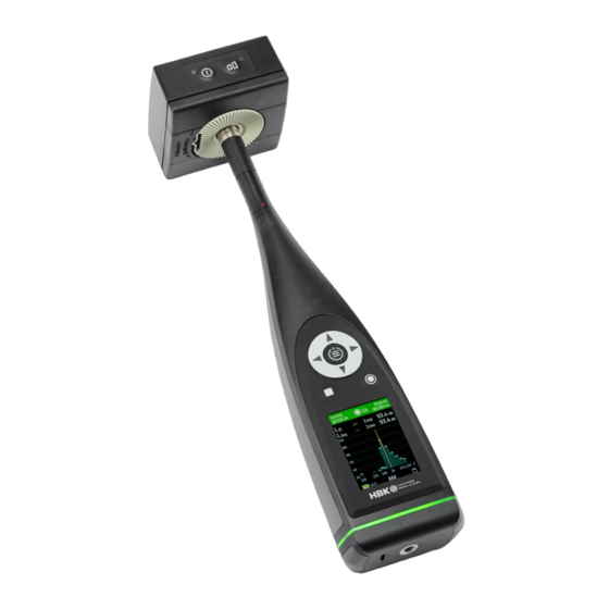
Page 9: System Overview
The three firmware variants fulfil the specifications described in this manual. The FW-2255-000 variant is a superset of the other variants. The three firmware variants are identical, except for the following restrictions on FW-2255-001 and FW-2255-002 compared to FW-2255-000: Installing and updating firmware can only be done by authorized personnel •... - Page 10 Instruction Manual Sound Level Meter Type 2255 – Page 8 of 133 Fig. 1.1 Hardware overview...
- Page 11 Instruction Manual Sound Level Meter Type 2255 – Page 9 of 133 Table 1.1 Hardware components needed for conformance testing of Sound Level Meter Type 2255 Quantity HBK Part Number Description Type 4966 Prepolarized Free-field ½" Condenser Microphone ZC-0043 Microphone Preamplifier...
-
Page 12: Block Diagrams
Instruction Manual Sound Level Meter Type 2255 – Page 10 of 133 1.2.4 Block Diagrams The block diagram of the sound level meter is shown in Fig. 1.2. Fig. 1.2 Block diagram of Type 2255... -
Page 13: Chapter 2 Short Guide To The Sound Level Meter
Instruction Manual Sound Level Meter Type 2255 – Page 11 of 133 Chapter 2 Short Guide to the Sound Level Meter Introduction This chapter contains a brief guide to the use of the sound level meter. The user interface of the sound level meter has: •... -
Page 14: About
2.3.1 About Go to About to see the sound level meter’s serial number, hardware version, firmware variant, and currently installed firmware version. 2.3.2 Measurement Settings The sound level meter can handle different applications with dedicated application-specific user Setup mode interfaces. Use to select the right interface. - Page 15 Instruction Manual Sound Level Meter Type 2255 – Page 13 of 133 Go to Measurement settings > Input to select: Microphone – This is automatically set when the preamplifier • has been connected. The preamplifier contains TEDS (Transducer Electronic Data Sheet) with information about the preamplifier and microphone.
- Page 16 Instruction Manual Sound Level Meter Type 2255 – Page 14 of 133 Go to Measurement settings > Broadband parameters to select the frequency weightings to use and the broadband parameters to measure. Use the arrow keys on the sound level meter to navigate...
-
Page 17: Display Settings
Instruction Manual Sound Level Meter Type 2255 – Page 15 of 133 Go to Measurement settings > Statistical parameters to select the Basis parameter for the or LAS) and spectrum statistics (LXF, LXS, LXeq) and up to broadband statistics (LAeq five percentiles. -
Page 18: System Settings
Instruction Manual Sound Level Meter Type 2255 – Page 16 of 133 2.3.4 System Settings Go to System settings to control regional settings, power settings, storage settings, network settings, advanced service settings and timer settings. Go to System settings > Regional settings > Language to select your preferred user interface language. - Page 19 Instruction Manual Sound Level Meter Type 2255 – Page 17 of 133 Go to System settings > Data management to set up backup settings for automatic backup and data retention. Data retention to Automatic or Manual. When set to Automatic, data that has been transferred to the PC apps or...
- Page 20 Instruction Manual Sound Level Meter Type 2255 – Page 18 of 133 Go to System settings > Network settings > Wi-Fi settings to Wi-Fi mode connect to the Wi-Fi. Set Airplane mode to switch Wi-Fi and Bluetooth off completely •...
-
Page 21: Status
Instruction Manual Sound Level Meter Type 2255 – Page 19 of 133 Go to System settings > Advanced settings to define many settings and functions that require the sound level meter to be Service mode set into before they can be accessed to prevent accidental changes to these settings. -
Page 22: Calibration
Instruction Manual Sound Level Meter Type 2255 – Page 20 of 133 Calibration Calibration is an adjustment of your sound level meter to measure and display correct values. The sensitivity of the microphone as well as the response of the electronic circuitry can vary slightly over time or could be affected by environmental conditions such as temperature and humidity. - Page 23 Instruction Manual Sound Level Meter Type 2255 – Page 21 of 133 Calibrate 5) Navigate up to and press ▷ to start the calibration process. 6) Fit Sound Calibrator Type 4231 carefully onto the microphone of the sound level meter. To avoid handling vibrations that disturb the calibration, rest the assembly in a roughly horizontal position on a table or other flat surface.
-
Page 24: Calibration Check Procedure
If the calibration deviates more than ±1.5 dB (±1.1 dB for firmware variant FW-2255-002) from the initial calibration, then the calibration is stopped without changing the calibration of the sound level meter. You can verify calibrations by navigating from the main menu: Calibration history > Calibrations. - Page 25 Instruction Manual Sound Level Meter Type 2255 – Page 23 of 133 4) Fit Sound Calibrator Type 4231 carefully onto the microphone of the sound level meter. To avoid handling vibrations that disturb the calibration, rest the assembly in a roughly horizontal position on a table or other flat surface.
-
Page 26: Measuring With The Sound Level Meter
Instruction Manual Sound Level Meter Type 2255 – Page 24 of 133 Please note: You can disable the automatic calibration check in System settings > Advanced settings > Calibration. Measuring with the Sound Level Meter Before a measurement is started and after it is stopped, the sound level meter displays an instantaneous Display settings broadband measurement. -
Page 27: Overload And Underrange
Instruction Manual Sound Level Meter Type 2255 – Page 25 of 133 2.5.3 Overload and Underrange The presence of overloads and underrange is shown in the measurement display. See section 2.15. Viewing Measurements There are several measurement displays (SLM, List, Spectrum, Profile, and About data). To navigate between them, use the △... -
Page 28: Viewing Saved Measurements
Instruction Manual Sound Level Meter Type 2255 – Page 26 of 133 Viewing Saved Measurements and in the main menu, go to Data explorer: To view saved measurements, press The internal disk can hold up to 1,300,000 single measurements with just one broadband parameter, or up to 800,000 single measurements with all broadband parameters, including broadband and spectral statistics and ten 1/3-octave spectra. -
Page 29: Mounting The Microphone/Sound Level Meter On A Tripod
Instruction Manual Sound Level Meter Type 2255 – Page 27 of 133 The optimum position for the microphone is best found by trying different positions and observing the resulting sound levels. For outdoor noise measurements (or indoor measurements exposed to air movement), mount Windscreen UA-1650 onto the microphone and preamplifier combination, ensuring it snaps into place over the windscreen sensor. -
Page 30: Measuring At Low Static Pressure
Instruction Manual Sound Level Meter Type 2255 – Page 28 of 133 2.11 Measuring at Low Static Pressure The microphone’s sensitivity and frequency response depend on the static ambient pressure. This is due to changes in air stiffness in the cavity behind the diaphragm, and changes in air mass in the small gap between the diaphragm and the backplate. -
Page 31: Mechanical Vibration
Instruction Manual Sound Level Meter Type 2255 – Page 29 of 133 2.12 Mechanical Vibration Mechanical vibration can affect indicated levels at low levels. Section 4.12.4 gives an indication of the level of these errors. The primary source to the vibration sensitivity is the microphone. It is most sensitive to vibrations coming from a direction perpendicular to the diaphragm. -
Page 32: Measured Quantities
Instruction Manual Sound Level Meter Type 2255 – Page 30 of 133 Table 2.1 Frequency weighting design goals Frequency Weightings Exact Nominal (1 decimal) Frequency Frequency (dB) (6 digits) (Hz) (Hz) 10.0000 -70.4 -38.2 -14.3 12.5893 -63.4 -33.2 -11.2 15.8489 -56.7... - Page 33 Instruction Manual Sound Level Meter Type 2255 – Page 31 of 133 Overload is indicated as a flashing (colour: red) on the screen and by a flashing red light ring. Overload is common to all results of instantaneous measurements. Underrange...
- Page 34 Instruction Manual Sound Level Meter Type 2255 – Page 32 of 133 The I time-weighted sound level is a continuous function of time and is expressed in decibels (dB). not displayed but is the base for AImax Instantaneous Time-weighted Sound Level...
-
Page 35: Timed Broadband Measurements
Instruction Manual Sound Level Meter Type 2255 – Page 33 of 133 2.14.2 Timed Broadband Measurements These measurements are only executed when is pressed and are paused when is pressed again Preset time or when has been pressed or when has expired, whichever occurs first. - Page 36 Instruction Manual Sound Level Meter Type 2255 – Page 34 of 133 Started • is the start time of the measurement, indicated as Elapsed • Δ is the measuring period, indicated as The maximum time-weighted sound level is expressed in decibels (dB).
- Page 37 Instruction Manual Sound Level Meter Type 2255 – Page 35 of 133 where ξ is a dummy variable of time integration over the averaging time interval. The symbol used by the sound level meter for A-frequency-weighted equivalent continuous I-weighted sound levels is:...
-
Page 38: Spectrum Measurements
Instruction Manual Sound Level Meter Type 2255 – Page 36 of 133 The symbols used by the sound level meter for sound exposure levels are (for A, B, C, and Z frequency weighting): Peak Sound Level The peak sound level,... -
Page 39: Timed Spectrum Measurements
Instruction Manual Sound Level Meter Type 2255 – Page 37 of 133 The symbols used by the sound level meter for instantaneous time-weighted sound level spectra are (for A, B, C, and Z frequency weighting and F and S time weighting): Overload is common to the broadband measurements. -
Page 40: Underrange
Instruction Manual Sound Level Meter Type 2255 – Page 38 of 133 2.15.2 Underrange Underrange indicates that one or more of the measured quantities time-weighted sound level, time- averaged sound level, or sound exposure level is momentary below the specified lower limit of the Linear Operating Range. -
Page 41: Chapter 3 Conformance Testing
Instruction Manual Sound Level Meter Type 2255 – Page 39 of 133 Chapter 3 Conformance Testing Introduction This chapter contains the information needed to conduct conformance testing according to the specified standards. Microphone, Accessories and Sound Fields The acoustical frequency response and calibration depends on the sound field, the microphone, the microphone accessories in use, and the electrical frequency response. -
Page 42: Electrical Substitute For Microphones
Instruction Manual Sound Level Meter Type 2255 – Page 40 of 133 The adjustment data, according to IEC 61672-1 paragraph 5.2.4, for Microphone Type 4966 with Sound Calibrator Type 4231 is 93.90 dB for the 94 dB setting of the calibrator. This value is built into the firmware... -
Page 43: Periodic Testing Of Acoustical Frequency Responses
Instruction Manual Sound Level Meter Type 2255 – Page 41 of 133 • The microphone and preamplifier assembly can be mounted separately in the Microphone Holder UA-1317. The Microphone Holder can be mounted using the tripod mount thread. To minimise the influence of reflections from the Microphone Holder, bend the holder part to an angle of 45°... -
Page 44: Emc Test Procedures
Instruction Manual Sound Level Meter Type 2255 – Page 42 of 133 EMC Test Procedures For Wi-Fi settings, see section 3.4. 3.9.1 Signal Sources for Immunity Test Acoustical Source for Testing According to IEC 61672 The acoustic signal, which is used during the immunity test according to IEC 61672, is applied to the microphone through a ½"... -
Page 45: Securing Of Cables During Emc Test
Instruction Manual Sound Level Meter Type 2255 – Page 43 of 133 3.9.3 Securing of Cables during EMC Test During test, any excessive cable is folded back on itself in an even number of figure eights. The microphone and preamplifier assembly is arranged approximately 25 cm above the sound level meter. - Page 46 Instruction Manual Sound Level Meter Type 2255 – Page 44 of 133 Fig. 3.4 The direction for the least immunity to radio-frequency fields Fig. 3.5 The direction for the least immunity to magnetic power-frequency fields Testing Immunity as a Sound Level Meter According to IEC 61672...
- Page 47 Instruction Manual Sound Level Meter Type 2255 – Page 45 of 133 Testing Immunity as a Frequency Analyzer According to IEC 61260 The highest Susceptibility (Susceptibility = 1/Immunity) for the filter sets is achieved when the sound level meter is set up as follows: 1) Make the connections described in section 3.9.4.
-
Page 48: Chapter 4 Specif Ications
The international IEC standards are adopted as European standards by CENELEC. When this happens, the letters IEC are replaced with EN and the number is retained. Sound Level Meter Type 2255 also conforms to these EN standards. -
Page 49: Reference Conditions For Acoustic Calibration
Instruction Manual Sound Level Meter Type 2255 – Page 47 of 133 Reference Conditions for Acoustic Calibration Reference Level Range: Only one level range exists and this is the reference level range. Reference Sound Pressure Level: 94.00 dB re. 20 μPa... -
Page 50: Frequency Responses
Expanded Uncertainties of Measurement with a probability of 95%. Please note: This range is not related to the production spread. The range is for a specific typical unit. The factory acceptance tests at HBK ensure that the ranges for all units are within limits in IEC 61672-1. 4.6.1 Electrical Frequency Responses The uncompensated electrical frequency response for the different frequency weightings is given in Fig. -
Page 51: Typical Low-Frequency Responses
Instruction Manual Sound Level Meter Type 2255 – Page 49 of 133 Fig. 4.1 Uncompensated electrical frequency response, corresponds to Table A.1 B&C 1000 10000 220012 4.6.2 Typical Low-frequency Responses The typical low-frequency responses for Z-frequency weighting are given in Fig. 4.2. -
Page 52: Acoustical Frequency Responses
Instruction Manual Sound Level Meter Type 2255 – Page 50 of 133 4.6.3 Acoustical Frequency Responses All the acoustical frequency responses are given for Z-frequency weighting. The A-, B-, and C-weighted acoustical frequency responses can be found by adding the appropriate response from the “Add to Acoustical Responses”... - Page 53 Instruction Manual Sound Level Meter Type 2255 – Page 51 of 133 Fig. 4.5 Free-field 0° frequency response for Microphone Type 4966, Microphone Preamplifier ZC-0043 and the sound level meter with the microphone preamplifier mounted directly on the sound level meter. Corresponds to the “Acoustical Response”...
-
Page 54: Diffuse-Field Frequency Responses
Instruction Manual Sound Level Meter Type 2255 – Page 52 of 133 4.6.5 Diffuse-field Frequency Responses The diffuse-field frequency responses (also called random-incidence frequency responses) with Z- frequency weighting are provided in Fig. 4.8 to Fig. 4.9 and Table A.6 to Table A.7. -
Page 55: Directional Responses
Instruction Manual Sound Level Meter Type 2255 – Page 53 of 133 Directional Responses This section gives directional responses for plane progressive sinusoidal sound waves normalised to the response in the reference direction. Influence of Windscreen UA-1650 is given as tables in Appendix A. - Page 56 Instruction Manual Sound Level Meter Type 2255 – Page 54 of 133 Fig. 4.10 Directional response for Microphone Type 4966 and Microphone Preamplifier ZC-0043 with the microphone preamplifier connected to a microphone extension cable. Corresponds to Table A.9 to Table A.11...
- Page 57 Instruction Manual Sound Level Meter Type 2255 – Page 55 of 133 Fig. 4.11 Sensitivity variations for Microphone Type 4966 and Microphone Preamplifier ZC-0043 with the microphone preamplifier connected to a microphone extension cable, at sound incidence angles with ± Ɵ° from the reference direction.
- Page 58 Instruction Manual Sound Level Meter Type 2255 – Page 56 of 133 Fig. 4.12 Directional response for Microphone Type 4966, Microphone Preamplifier ZC-0043 and the sound level meter with the microphone preamplifier mounted directly on the sound level meter, measured in a plane parallel...
- Page 59 Instruction Manual Sound Level Meter Type 2255 – Page 57 of 133 Fig. 4.13 Directional response for Microphone Type 4966, Microphone Preamplifier ZC-0043 and the sound level meter with the microphone preamplifier mounted directly on the sound level meter, measured in a plane...
- Page 60 Instruction Manual Sound Level Meter Type 2255 – Page 58 of 133 Fig. 4.14 Sensitivity variations of Microphone Type 4966, Microphone Preamplifier ZC-0043 and the sound level meter with the microphone preamplifier mounted directly on the sound level meter, at sound incidence angles within ±...
- Page 61 Instruction Manual Sound Level Meter Type 2255 – Page 59 of 133 Fig. 4.15 Directional response for Windscreen UA-1650, Microphone Type 4966 and Microphone Preamplifier ZC-0043 with the microphone preamplifier connected to a microphone extension cable. Corresponds to Table A.20...
- Page 62 Instruction Manual Sound Level Meter Type 2255 – Page 60 of 133 Fig. 4.16 Sensitivity variations for Windscreen UA-1650, Microphone Type 4966 and Microphone Preamplifier ZC-0043 with the microphone preamplifier connected to a microphone extension cable, at sound incidence angles within ±...
- Page 63 Instruction Manual Sound Level Meter Type 2255 – Page 61 of 133 Fig. 4.17 Directional response for Windscreen UA-1650, Microphone Type 4966, Microphone Preamplifier ZC-0043 and the sound level meter with the microphone preamplifier mounted directly on the sound level meter, measured...
- Page 64 Instruction Manual Sound Level Meter Type 2255 – Page 62 of 133 Fig. 4.18 Directional response for Windscreen UA-1650, Microphone Type 4966, Microphone Preamplifier ZC-0043 and the sound level meter with the microphone preamplifier mounted directly on the sound level meter, measured...
- Page 65 Instruction Manual Sound Level Meter Type 2255 – Page 63 of 133 Fig. 4.19 Sensitivity variations of Windscreen UA-1650, Microphone Type 4966, Microphone Preamplifier ZC-0043 and the sound level meter with the microphone preamplifier mounted directly on the sound level meter, at sound incidence angles within ±...
-
Page 66: Self-Generated Noise
Instruction Manual Sound Level Meter Type 2255 – Page 64 of 133 Self-generated Noise Self-generated noise is given for nominal microphone Open Circuit Sensitivity, with Measurement settings > Input > Sound field set to Free-field and no microphone accessories selected. -
Page 67: Typical Self-Generated Noise Spectra
Instruction Manual Sound Level Meter Type 2255 – Page 65 of 133 4.8.3 Typical Self-generated Noise Spectra Typical spectra for self-generated noise are shown in Fig. 4.20 to Fig. 4.21. Fig. 4.20 Typical self-generated noise, 1/1-octave band Microphone Electrical Total 220030 Fig. -
Page 68: Measuring Ranges
Instruction Manual Sound Level Meter Type 2255 – Page 66 of 133 Measuring Ranges The "Upper Limit" in the following sections is based on the guaranteed worst-case limit for the sound level meter and the nominal Open Circuit Sensitivity of the microphone. The Overload Limit can, due to tolerances in the sound level meter, be up to 0.6 dB higher than the Upper Limit specified in this manual,... -
Page 69: Indicator Range
Instruction Manual Sound Level Meter Type 2255 – Page 67 of 133 4.9.4 Indicator Range Indicator Range according to the international standard IEC 60804: Table 4.5 Indicator Range Lower Limit Upper Limit Z-weighting A-weighting B-weighting C-weighting Z-weighting (dB) Extended (dB) -
Page 70: Pulse Range
Instruction Manual Sound Level Meter Type 2255 – Page 68 of 133 4.9.6 Pulse Range Pulse Range according to the international standard IEC 60804 is the difference between the Upper Limit and Lower Limit in the following table: Table 4.7 Pulse Range... -
Page 71: Detectors
Instruction Manual Sound Level Meter Type 2255 – Page 69 of 133 4.10 Detectors Display-update Rates: broadband bars and spectra every 0.25 seconds; all other spectra and numbers every 1 second. 4.10.1 Exponential Averaging Exponential Averaging Times: Fast (250 ms), Slow (2000 ms), Impulse (70 ms + 1500 ms hold time... -
Page 72: Linear Averaging
Instruction Manual Sound Level Meter Type 2255 – Page 70 of 133 4.10.2 Linear Averaging Linear Averaging Times: 1 second to 32 days, in steps of 1 second Settling Time According to IEC 60804: <3 seconds Nominal Delay Time between operation of the reset facility and re-initiation of a measurement according to IEC 61672-1: <2 seconds... -
Page 73: 1/3-Octave Band Centre Frequencies
Instruction Manual Sound Level Meter Type 2255 – Page 71 of 133 Fig. 4.23 The shapes of the 1/1-octave band filters (from 0 to –3.5 dB). The innermost and outermost curves show IEC 61260 limits 4.11.2 1/3-octave Band Centre Frequencies Nominal: 12.5 Hz, 16 Hz, 20 Hz, 25 Hz, 31.5 Hz, 40 Hz, 50 Hz, 63 Hz, 80 Hz, 100 Hz, 125 Hz, 160 Hz, 200 Hz,... -
Page 74: Linear Operating Range
Instruction Manual Sound Level Meter Type 2255 – Page 72 of 133 Fig. 4.25 The shapes of the 1/3-octave band filters (from 0 to –3.5 dB). The innermost and outermost curves show IEC 61260 limits 4.11.3 Linear Operating Range Linear Operating Range according to the international standard IEC 61260, for electrical input, for all filters in the filter banks: Table 4.11 Linear Operating Range... -
Page 75: Octave Band Time Constants
Instruction Manual Sound Level Meter Type 2255 – Page 73 of 133 4.11.5 Octave Band Time Constants At low centre frequencies, the B*T product for time weightings becomes too small to give statistically reliable measurements. To overcome this, the Fast time constant (125 ms) and the Slow time constant (1000 ms) are replaced by progressively longer time constants with decreasing centre frequencies (and corresponding bandwidths). -
Page 76: Wireless Interface To The Sound Level Meter
Sound Level Meter Type 2255 incorporates a Wi-Fi/Bluetooth radio module, which has been tested to comply with European Radio Equipment directive (RED) 2014/53/EU. Sound Level Meter Type 2255 has been tested by a qualified test house and complies with the requirements in the EN 62209-2:2010 specifications for body-worn use and for hand-held use. -
Page 77: Electrical Interface To The Sound Level Meter
Instruction Manual Sound Level Meter Type 2255 – Page 75 of 133 WARNING: Any changes or modifications not expressly approved by the party responsible for compliance could void the user’s authority to operate the equipment. Prohibition of Co-location: This device and its antenna(s) must not be co-located or operated in conjunction with any other antenna or transmitter. -
Page 78: Digital Interfaces
Instruction Manual Sound Level Meter Type 2255 – Page 76 of 133 Load Impedance: >15 kΩ ⵏⵏ< 1 nF for <0.2 dB attenuation from DC to 20 kHz, short-circuit proof witho ut affecting the measurement results Max DC Offset: ±15 mV 4.14.2... -
Page 79: Battery
Instruction Manual Sound Level Meter Type 2255 – Page 77 of 133 4.15.2 Battery Built-in rechargeable Li-Ion battery Voltage: 3.6 V (nominal) Capacity: 6.7 Ah (typical at 25°C) Typical Operating Time: >13 hours. However, if the sound level meter is used in low temperatures or there is extensive use of the display backlight, this may reduce the time Battery Cycle Life: >500 complete charge/discharge cycles with 80% of initial capacity remaining... -
Page 80: Mark Compliance
Instruction Manual Sound Level Meter Type 2255 – Page 78 of 133 4.18 Mark Compliance... - Page 81 Instruction Manual Sound Level Meter Type 2255 – Page 79 of 133 Please note: The above is only guaranteed using accessories listed in Table 1.2.
-
Page 82: Appendix A Tables
Instruction Manual Sound Level Meter Type 2255 – Page 80 of 133 Appendix A Tables Electrical Frequency Responses Uncompensated electrical frequency responses for the different frequency weightings. Please see the instructions in section 3.2.2 on how to ensure an uncompensated electrical frequency response. - Page 83 Instruction Manual Sound Level Meter Type 2255 – Page 81 of 133 Table A.1 Uncompensated electrical frequency responses Nominal Exact Electrical responses Add to Acoustic Responses Frequency Frequency A-weighting B-weighting C-weighting Z-weighting A-weighting B-weighting C-weighting 63.0957 -26.24 -9.39 -0.86 0.00 -26.24...
-
Page 84: Free-Field Frequency Responses
Instruction Manual Sound Level Meter Type 2255 – Page 82 of 133 Free-field Frequency Responses Frequency responses with Z-frequency weighting. Measured with plane progressive sinusoidal sound Sound field set to Free-field, see waves incident from the reference direction and the sound level meter’s... - Page 85 Instruction Manual Sound Level Meter Type 2255 – Page 83 of 133 Table A.2 Free-field 0° frequency response for Microphone Type 4966, Microphone Preamplifier ZC-0043 and the sound level meter’s electrical response with the microphone preamplifier connected to a microphone extension cable...
- Page 86 Instruction Manual Sound Level Meter Type 2255 – Page 84 of 133 Table A.3 Free-field 0° frequency response for Microphone Type 4966, Microphone Preamplifier ZC-0043 and the sound level meter with the microphone preamplifier mounted directly on the sound level meter...
- Page 87 Instruction Manual Sound Level Meter Type 2255 – Page 85 of 133 Table A.4 Free-field 0° frequency response for Windscreen UA-1650, Microphone Type 4966, Microphone Preamplifier ZC-0043 and the sound level meter’s electrical response, with the microphone preamplifier connected to a microphone extension cable...
- Page 88 Instruction Manual Sound Level Meter Type 2255 – Page 86 of 133 Table A.5 Free-field 0° frequency response for Windscreen UA-1650, Microphone Type 4966, Microphone Preamplifier ZC-0043 and the sound level meter with the microphone preamplifier mounted directly on the sound level meter...
-
Page 89: Diffuse-Field Frequency Responses
Instruction Manual Sound Level Meter Type 2255 – Page 87 of 133 Diffuse-field Frequency Responses Diffuse-field frequency responses with Z-frequency weighting. Measured with sounds at random incidence Sound field set to Diffuse-field, see section 4.6. and the sound level meter’s... - Page 90 Instruction Manual Sound Level Meter Type 2255 – Page 88 of 133 Table A.6 Diffuse-field frequency response for Microphone Type 4966, Microphone Preamplifier ZC-0043 and the sound level meter with or without the microphone preamplifier connected to a microphone extension cable...
- Page 91 Instruction Manual Sound Level Meter Type 2255 – Page 89 of 133 Table A.7 Diffuse-field frequency response for Windscreen UA-1650, Microphone Type 4966, Microphone Preamplifier ZC-0043 and the sound level meter with or without the microphone preamplifier connected to a microphone extension cable...
-
Page 92: Free-Field Frequency Responses For Diffuse-Field Calibrated Instruments
Instruction Manual Sound Level Meter Type 2255 – Page 90 of 133 Free-field Frequency Responses for Diffuse-field Calibrated Instruments Free-field frequency response in the reference direction for diffuse-field calibrated instruments according to IEC 60651 and IEC 60804. Measured with plane progressive sinusoidal sound waves incident from the Sound field set to Diffuse-field, see section 4.6. - Page 93 Instruction Manual Sound Level Meter Type 2255 – Page 91 of 133 Table A.8 Free-field 0° frequency response with the Sound Field Correction parameter set to Diffuse-field for the configurations for which there are specified normal free-field responses Nominal Exact...
-
Page 94: Directional Responses
Instruction Manual Sound Level Meter Type 2255 – Page 92 of 133 Directional Responses Directional responses for plane progressive sinusoidal sound waves normalised to the response in the reference direction, including sensitivity variations. - Page 95 Instruction Manual Sound Level Meter Type 2255 – Page 93 of 133 Table A.9 Directional response for microphone and preamplifier connected to the sound level meter using a microphone extension cable, 250 Hz – 2.8 kHz Nominal Frequency Angle 250 Hz...
- Page 96 Instruction Manual Sound Level Meter Type 2255 – Page 94 of 133 Table A.10 Directional response for microphone and preamplifier connected to the sound level meter using a microphone extension cable, 3.15 kHz – 10 kHz Nominal Frequency Angle 3.15 kHz 3.55 kHz...
- Page 97 Instruction Manual Sound Level Meter Type 2255 – Page 95 of 133 Table A.11 Directional response for microphone and preamplifier connected to the sound level meter using a microphone extension cable, 10.6 kHz – 20 kHz Nominal Frequency Angle 10.6 kHz 11.2 kHz...
- Page 98 Instruction Manual Sound Level Meter Type 2255 – Page 96 of 133 Table A.12 Sensitivity variations for microphone and preamplifier connected to the sound level meter using a microphone extension cable, at sound incidence angles within ±Ɵ ° from the reference direction...
- Page 99 Instruction Manual Sound Level Meter Type 2255 – Page 97 of 133 Table A.13 Directional response for microphone and preamplifier mounted directly on the sound level meter, measured in a plane parallel to the display and along the microphone’s axis, 250 Hz – 2.8 kHz...
- Page 100 Instruction Manual Sound Level Meter Type 2255 – Page 98 of 133 Table A.14 Directional response for microphone and preamplifier mounted directly on the sound level meter, measured in a plane parallel to the display and along the microphone’s axis, 3.15 kHz – 10 kHz Nominal Frequency Angle 3.15 kHz...
- Page 101 Instruction Manual Sound Level Meter Type 2255 – Page 99 of 133 Table A.15 Directional response for microphone and preamplifier mounted directly on the sound level meter, measured in a plane parallel to the display and along the microphone’s axis, 10.6 kHz – 20 kHz...
- Page 102 Instruction Manual Sound Level Meter Type 2255 – Page 100 of 133 Table A.16 Directional response for microphone and preamplifier mounted directly on the sound level meter, measured in a plane perpendicular to the display and along the microphone’s axis, 250 Hz – 2.8 kHz...
- Page 103 Instruction Manual Sound Level Meter Type 2255 – Page 101 of 133 Table A.17 Directional response for microphone and preamplifier mounted directly on the sound level meter, measured in a plane perpendicular to the display and along the microphone’s axis, 3.15 kHz – 10 kHz Nominal Frequency Angle 3.15 kHz...
- Page 104 Instruction Manual Sound Level Meter Type 2255 – Page 102 of 133 Table A.18 Directional response for microphone and preamplifier mounted directly on the sound level meter, measured in a plane perpendicular to the display and along the microphone’s axis, 10.6 kHz – 20 kHz...
- Page 105 Instruction Manual Sound Level Meter Type 2255 – Page 103 of 133 Table A.19 Sensitivity variations for microphone and preamplifier mounted directly on the sound level meter, at sound incidence angles within ±Ɵ ° from the reference direction Nominal Exact...
- Page 106 Instruction Manual Sound Level Meter Type 2255 – Page 104 of 133 Table A.20 Directional response for microphone and preamplifier with windscreen UA-1650 connected to the sound level meter using a microphone extension cable, 250 Hz – 2.8 kHz Nominal Frequency...
- Page 107 Instruction Manual Sound Level Meter Type 2255 – Page 105 of 133 Table A.21 Directional response for microphone and preamplifier with windscreen UA-1650 connected to the sound level meter using a microphone extension cable, 3.15 kHz – 10 kHz Nominal Frequency Angle 3.15 kHz...
- Page 108 Instruction Manual Sound Level Meter Type 2255 – Page 106 of 133 Table A.22 Directional response for microphone and preamplifier with windscreen UA-1650 connected to the sound level meter using a microphone extension cable, 10.6 kHz – 20 kHz Nominal Frequency Angle 10.6 kHz...
- Page 109 Instruction Manual Sound Level Meter Type 2255 – Page 107 of 133 Table A.23 Sensitivity variations for microphone and preamplifier with windscreen UA-1650 connected to the sound level meter using a microphone extension cable, at sound incidence angles within ±Ɵ ° from the reference direction...
- Page 110 Instruction Manual Sound Level Meter Type 2255 – Page 108 of 133 Table A.24 Directional response for microphone and preamplifier with windscreen UA-1650 mounted directly on the sound level meter, measured in a plane parallel to the display and along the microphone’s axis, 250 Hz – 2.8 kHz...
- Page 111 Instruction Manual Sound Level Meter Type 2255 – Page 109 of 133 Table A.25 Directional response for microphone and preamplifier with windscreen UA-1650 mounted directly on the sound level meter, measured in a plane parallel to the display and along the microphone’s axis, 3.15 kHz – 10 kHz Nominal Frequency Angle 3.15 kHz...
- Page 112 Instruction Manual Sound Level Meter Type 2255 – Page 110 of 133 Table A.26 Directional response for microphone and preamplifier with windscreen UA-1650 mounted directly on the sound level meter, measured in a plane parallel to the display and along the microphone’s axis, 10.6 kHz – 20 kHz...
- Page 113 Instruction Manual Sound Level Meter Type 2255 – Page 111 of 133 Table A.27 Directional response for microphone and preamplifier with windscreen UA-1650 mounted directly on the sound level meter, measured in a plane perpendicular to the display and along the microphone’s axis, 250 Hz – 2.8 kHz...
- Page 114 Instruction Manual Sound Level Meter Type 2255 – Page 112 of 133 Table A.28 Directional response for microphone and preamplifier with windscreen UA-1650 mounted directly on the sound level meter, measured in a plane perpendicular to the display and along the microphone’s axis, 3.15 kHz – 10 kHz Nominal Frequency Angle 3.15 kHz...
- Page 115 Instruction Manual Sound Level Meter Type 2255 – Page 113 of 133 Table A.29 Directional response for microphone and preamplifier with windscreen UA-1650 mounted directly on the sound level meter, measured in a plane perpendicular to the display and along the microphone’s axis, 10.6 kHz – 20 kHz...
- Page 116 Instruction Manual Sound Level Meter Type 2255 – Page 114 of 133 Table A.30 Sensitivity variations for microphone and preamplifier with windscreen UA-1650 mounted directly on the sound level meter, at sound incidence angles within ±Ɵ ° from the reference direction...
- Page 117 Instruction Manual Sound Level Meter Type 2255 – Page 115 of 133 Table A.31 Influence of the sound level meter body on the directional response, measured in a plane parallel to the display and along the microphone’s axis, 250 Hz – 2.8 kHz...
- Page 118 Instruction Manual Sound Level Meter Type 2255 – Page 116 of 133 Table A.32 Influence of the sound level meter body on the directional response, measured in a plane parallel to the display and along the microphone’s axis, 3.15 kHz – 10 kHz Nominal Frequency Angle 3.15 kHz...
- Page 119 Instruction Manual Sound Level Meter Type 2255 – Page 117 of 133 Table A.33 Influence of the sound level meter body on the directional response, measured in a plane parallel to the display and along the microphone’s axis, 10.6 kHz – 20 kHz...
- Page 120 Instruction Manual Sound Level Meter Type 2255 – Page 118 of 133 Table A.34 Influence of the sound level meter body on the directional response, measured in a plane perpendicular to the display and along the microphone’s axis, 250 Hz – 2.8 kHz...
- Page 121 Instruction Manual Sound Level Meter Type 2255 – Page 119 of 133 Table A.35 Influence of the sound level meter body on the directional response, measured in a plane perpendicular to the display and along the microphone’s axis, 3.15 kHz – 10 kHz Nominal Frequency Angle 3.15 kHz...
- Page 122 Instruction Manual Sound Level Meter Type 2255 – Page 120 of 133 Table A.36 Influence of the sound level meter body on the directional response, measured in a plane perpendicular to the display and along the microphone’s axis, 10.6 kHz – 20 kHz...
- Page 123 Instruction Manual Sound Level Meter Type 2255 – Page 121 of 133 Table A.37 Influence of Windscreen UA-1650 on the directional response, with or without Microphone Preamplifier ZC-0043 connected to a microphone extension cable, 250 Hz – 2.8 kHz Nominal Frequency...
- Page 124 Instruction Manual Sound Level Meter Type 2255 – Page 122 of 133 Table A.38 Influence of Windscreen UA-1650 on the directional response, with or without Microphone Preamplifier ZC-0043 connected to a microphone extension cable, 3.15 kHz – 10 kHz Nominal Frequency Angle 3.15 kHz...
- Page 125 Instruction Manual Sound Level Meter Type 2255 – Page 123 of 133 Table A.39 Influence of Windscreen UA-1650 on the directional response, with or without Microphone Preamplifier ZC-0043 connected to a microphone extension cable, 10.6 kHz – 20 kHz Nominal Frequency Angle 10.6 kHz...
-
Page 126: Periodic Testing Of Acoustical Frequency Responses
Instruction Manual Sound Level Meter Type 2255 – Page 124 of 133 Periodic Testing of Acoustical Frequency Responses This section gives the correction data that shall be applied to sound levels displayed in response to the sound pressure produced by Multifunction Acoustic Calibrator Type 4226, or in response to simulation of... - Page 127 Instruction Manual Sound Level Meter Type 2255 – Page 125 of 133 Table A.41 Correction data for acoustical test with Electrostatic Actuator UA-0033. Data are given for microphone and preamplifier mounted directly on the sound level meter Nominal Exact Microphone Expanded Mic.
-
Page 128: Appendix B Cross-Ref Erences To Standards
Instruction Manual Sound Level Meter Type 2255 – Page 126 of 133 Appendix B Cross-references to Standards Introduction This appendix provides cross-references between specific paragraphs in the standards that require topics to be documented in an instruction manual and the corresponding sections in this manual that conform to those paragraphs. - Page 129 Instruction Manual Sound Level Meter Type 2255 – Page 127 of 133 5.3.3.1 Table A.4 Table A.7 Table A.20 - Table A.22 5.3.4.1 A.2, A.3 5.3.5.1 3.6, Table A.6 5.4.5 5.5.5 4.7, A.5 5.5.8 2.13 5.6.10 4.9.7 5.6.11 4.9.7 5.7.1 4.8.1...
- Page 130 Instruction Manual Sound Level Meter Type 2255 – Page 128 of 133 6.2.2 2.11 6.3.2 B.3 e 6.5.2 B.3 g 6.6.1 3.9.5 6.6.3 3.9.5 6.6.5 B.3 h 6.6.10 B.3 h 2.12 4.6, 4.7, Table A.4 Table A.7 Table A.20 - Table A.22 2.3, 2.6...
- Page 131 Instruction Manual Sound Level Meter Type 2255 – Page 129 of 133 9.2.3 d 4.15.1 9.2.4 a 9.2.4 b 9.2.4 c 9.2.5 a A.2, A.3, A.5 9.2.5 b 4.6.4, 4.6.5, A.2, A.3 9.2.5 c Table A.4, Table A.7 Table A.20 - Table A.22 9.2.5 d...
- Page 132 Instruction Manual Sound Level Meter Type 2255 – Page 130 of 133 9.3 f 4.9.7 9.3 g 4.9.7 9.3 h 3.3.2 9.3 i 4.8, 4.8.1 9.3 j 4.9.1, 3.3.2 9.3 k B.3 m 9.3 l 4.12.1 9.3 m B.3 g 9.3 n...
- Page 133 Instruction Manual Sound Level Meter Type 2255 – Page 131 of 133 IEC 61260:2014 Standard’s This Manual’s Paragraph Section 5.1.4 1.2.3, 3.8, 3.9 5.9.1 4.11 5.9.2 B.3 i 5.13.1 4.11.3 5.13.6 B.3 a 5.13.8 4.11.3 5.14.4 4.11.1, 4.11.2 5.17.1 2.15.1 5.18.1...
- Page 134 Instruction Manual Sound Level Meter Type 2255 – Page 132 of 133 7.3 c) B.3 i 7.3 d) B.3 k 7.3 e) B.3 l, 4.14.1 7.3 f) 1.2.3, 3.8, 3.9 7.3 g) B.3 f 7.3 h) 3.9.5 7.3 i) 7.3 j) 7.3 k)
-
Page 135: Irrelevant Topics
Instruction Manual Sound Level Meter Type 2255 – Page 133 of 133 Irrelevant Topics This section provides a list of the cross-references to topics that are not provided in, or are irrelevant to this product. References in the previous tables are made to the following items: a. - Page 138 www.bksv.com...
Need help?
Do you have a question about the 2255 and is the answer not in the manual?
Questions and answers