Table of Contents
Advertisement
Quick Links
UG349: MGM13S12 Blue Gecko Module
Radio Board User's Guide
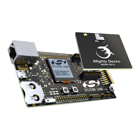
A Wireless Starter Kit with the BRD4305E Radio Board is an ex-
cellent starting point to get familiar with the MGM13S Mighty
Gecko SiP Module. It also provides the necessary tools for devel-
oping a Silicon Labs wireless application.
BRD4305E contains the MGM13S12 Module, and it is a plug-in board for the Wireless
Starter Kit Mainboard.
The Wireless Starter Kit Mainboard contains an on-board J-Link debugger with a Packet
Trace Interface and a virtual COM port, enabling application development and debugging
the attached radio board as well as external hardware. The mainboard also contains
sensors and peripherals for easy demonstration of some of the MGM13S's many capa-
bilities.
This document describes how to use the BRD4305E Radio Board together with a Wire-
less Starter Kit Mainboard.
silabs.com | Building a more connected world.
BRD4305E RADIO BOARD FEATURES
• MGM13S Mighty Gecko SiP Module with
512 kB Flash, 64 kB RAM. Fully integrated
chip antenna, RF matching network, RF
crystal and decoupling capacitors
(MGM13S12F512GA-V2).
• 32.768 kHz crystal for LFXO
• 8 Mbit low-power serial flash for over-the-
air upgrades.
WIRELESS STK MAINBOARD FEATURES
• Advanced Energy Monitor
• Packet Trace Interface
• Virtual COM Port
• SEGGER J-Link on-board debugger
• External device debugging
• Ethernet and USB connectivity
• Silicon Labs Si7021 Relative Humidity and
Temperature sensor
• Low Power 128x128 pixel Memory LCD
• User LEDs / Pushbuttons
• 20-pin 2.54 mm EXP header
• Breakout pads for Module I/O
• CR2032 coin cell battery support
SOFTWARE SUPPORT
• Simplicity Studio™
• Energy Profiler
• Network Analyzer
ORDERING INFORMATION
• SLWRB4305E
Rev. 1.0
Advertisement
Table of Contents

Related Manuals for Silicon Laboratories UG349: MGM13S12


Summary of Contents for Silicon Laboratories UG349: MGM13S12
- Page 1 UG349: MGM13S12 Blue Gecko Module Radio Board User's Guide A Wireless Starter Kit with the BRD4305E Radio Board is an ex- cellent starting point to get familiar with the MGM13S Mighty BRD4305E RADIO BOARD FEATURES Gecko SiP Module. It also provides the necessary tools for devel- •...
-
Page 2: Table Of Contents
Table of Contents 1. Introduction ....... . 4 1.1 Radio Boards ......4 1.2 Ordering Information . - Page 3 7.1 Introduction.......25 7.2 Theory of Operation ......25 7.3 AEM Accuracy and Performance .
-
Page 4: Introduction
UG349: MGM13S12 Blue Gecko Module Radio Board User's Guide Introduction 1. Introduction The MGM13S12 Mighty Gecko Module is featured on a radio board that plugs directly into a Wireless Starter Kit (WSTK) Mainboard. The mainboard features several tools for easy evaluation and development of wireless applications. An on-board J-Link debugger ena- bles programming and debugging on the target device over USB or Ethernet. -
Page 5: Hardware Overview
UG349: MGM13S12 Blue Gecko Module Radio Board User's Guide Hardware Overview 2. Hardware Overview 2.1 Hardware Layout The layout of the MGM13S12 Mighty Gecko Module Wireless Starter Kit is shown in the figure below. Radio Board Breakout Pads Plug-in Radio Board... -
Page 6: Block Diagram
UG349: MGM13S12 Blue Gecko Module Radio Board User's Guide Hardware Overview 2.2 Block Diagram An overview of the MGM13S12 Mighty Gecko Module Wireless Starter Kit is shown in the figure below. Wireless STK Mainboard Board USB Mini-B Controller RJ-45 Ethernet... -
Page 7: Connectors
UG349: MGM13S12 Blue Gecko Module Radio Board User's Guide Connectors 3. Connectors This chapter gives you an overview of the Wireless STK Mainboard connectivity. The placement of the connectors are shown in the figure below. Ethernet Connector J-Link USB Connector... -
Page 8: Breakout Pads
UG349: MGM13S12 Blue Gecko Module Radio Board User's Guide Connectors 3.3 Breakout Pads Most pins of the MGM13S are routed from the radio board to breakout pads at the top and bottom edges of the Wireless STK Main- board. A 2.54 mm pitch pin header can be soldered on for easy access to the pins. The figure below shows you how the pins of the MGM13S map to the pin numbers printed on the breakout pads. -
Page 9: Exp Header
UG349: MGM13S12 Blue Gecko Module Radio Board User's Guide Connectors 3.4 EXP Header The EXP header is an angled 20-pin expansion header provided to allow connection of peripherals or plugin boards to the kit. It is loca- ted on the right-hand side of the mainboard, and it contains a number of I/O pins that can be used with most of the MGM13S Mighty Gecko's features. -
Page 10: Exp Header Pinout
UG349: MGM13S12 Blue Gecko Module Radio Board User's Guide Connectors 3.4.1 EXP Header Pinout The pin-routing on the MGM13S is very flexible, so most peripherals can be routed to any pin. However, many pins are shared between the EXP header and other functions on the Wireless STK Mainboard. The table below includes an overview of the mainboard features that share pins with the EXP header. -
Page 11: Debug Connector
UG349: MGM13S12 Blue Gecko Module Radio Board User's Guide Connectors 3.5 Debug Connector The debug connector serves multiple purposes based on the "debug mode" setting which can be configured in Simplicity Studio. When the debug mode is set to "Debug IN", the debug connector can be used to connect an external debugger to the MGM13S on the radio board. -
Page 12: Simplicity Connector
UG349: MGM13S12 Blue Gecko Module Radio Board User's Guide Connectors 3.6 Simplicity Connector The Simplicity Connector enables the advanced debugging features, such as the AEM, the virtual COM port, and the Packet Trace Interface, to be used towards an external target. The pinout is illustrated in the figure below. -
Page 13: Debug Adapter
UG349: MGM13S12 Blue Gecko Module Radio Board User's Guide Connectors 3.7 Debug Adapter BRD8010A STK/WSTK Debug Adapter is an adapter board which plugs directly into the debug connector and the Simplicity Connector on the mainboard. It combines selected functionality from the two connectors to a smaller footprint 10-pin connector, which is more suitable for space constrained designs. -
Page 14: Power Supply And Reset
UG349: MGM13S12 Blue Gecko Module Radio Board User's Guide Power Supply and Reset 4. Power Supply and Reset 4.1 Radio Board Power Selection The MGM13S on a Wireless Starter Kit can be powered by one of these sources: • The debug USB cable •... -
Page 15: Board Controller Power
UG349: MGM13S12 Blue Gecko Module Radio Board User's Guide Power Supply and Reset 4.2 Board Controller Power The board controller is responsible for important features, such as the debugger and the AEM, and is powered exclusively through the USB port in the top left corner of the board. This part of the kit resides on a separate power domain, so a different power source can be selected for the target device while retaining debugging functionality. -
Page 16: Peripherals
UG349: MGM13S12 Blue Gecko Module Radio Board User's Guide Peripherals 5. Peripherals The starter kit has a set of peripherals that showcase some of the features of the MGM13S. Be aware that most MGM13S I/O routed to peripherals are also routed to the breakout pads. This must be taken into consideration when using the breakout pads for your application. -
Page 17: Memory Lcd-Tft Display
UG349: MGM13S12 Blue Gecko Module Radio Board User's Guide Peripherals 5.2 Memory LCD-TFT Display A 1.28-inch SHARP Memory LCD-TFT is available on the kit to enable interactive applications to be developed. The display has a high resolution of 128 by 128 pixels and consumes very little power. It is a reflective monochrome display, so each pixel can only be light or dark, and no backlight is needed in normal daylight conditions. -
Page 18: Serial Flash
UG349: MGM13S12 Blue Gecko Module Radio Board User's Guide Peripherals 5.3 Serial Flash The BRD4305E Radio Board is equipped with an 8 Mbit Macronix MX25R SPI flash that is connected directly to the MGM13S. The figure below shows how the serial flash is connected to the MGM13S. -
Page 19: Si7021 Relative Humidity And Temperature Sensor
UG349: MGM13S12 Blue Gecko Module Radio Board User's Guide Peripherals 5.4 Si7021 Relative Humidity and Temperature Sensor The Si7021 I C relative humidity and temperature sensor is a monolithic CMOS IC integrating humidity and temperature sensor ele- ments, an analog-to-digital converter, signal processing, calibration data, and an I C Interface. -
Page 20: Virtual Com Port
UG349: MGM13S12 Blue Gecko Module Radio Board User's Guide Peripherals 5.5 Virtual COM Port An asynchronous serial connection to the board controller is provided for application data transfer between a host PC and the target MGM13S. This eliminates the need for an external serial port adapter. -
Page 21: Host Interfaces
UG349: MGM13S12 Blue Gecko Module Radio Board User's Guide Peripherals 5.5.1 Host Interfaces Data sent to the board controller through the VCOM interface is available in two different ways to the user. At the same time, data can be sent to the target device using these interfaces: •... -
Page 22: Hardware Handshake
UG349: MGM13S12 Blue Gecko Module Radio Board User's Guide Peripherals 5.5.3 Hardware Handshake The VCOM peripheral supports basic RTS/CTS flow control. VCOM_CTS (target clear to send) is a signal that is output from the board controller and input to the target device. The board controller de-asserts this pin whenever its input buffer is full and it is unable to accept more data from the target device. -
Page 23: Board Controller
UG349: MGM13S12 Blue Gecko Module Radio Board User's Guide Board Controller 6. Board Controller The Wireless STK Mainboard contains a dedicated microcontroller for some of the advanced kit features provided. This microcontroller is referred to as the board controller and is not programmable by the user. The board controller acts as an interface between the host PC and the target device on the radio board, as well as handling some house-keeping functions on the board. -
Page 24: Command Examples
UG349: MGM13S12 Blue Gecko Module Radio Board User's Guide Board Controller 6.1.3 Command Examples PTI Configuration pti config 0 efruart 1600000 Configures PTI to use the "EFRUART" mode at 1.6 Mb/s. Serial Port Configuration serial config vcom handshake enable Enables hardware handshake on the VCOM UART connection. -
Page 25: Advanced Energy Monitor
UG349: MGM13S12 Blue Gecko Module Radio Board User's Guide Advanced Energy Monitor 7. Advanced Energy Monitor 7.1 Introduction Any embedded developer seeking to make his embedded code spend as little energy as the underlying architecture supports needs tools to easily and quickly discover inefficiencies in the running application. -
Page 26: Aem Accuracy And Performance
UG349: MGM13S12 Blue Gecko Module Radio Board User's Guide Advanced Energy Monitor 7.3 AEM Accuracy and Performance The AEM is capable of measuring currents in the range of 0.1 µA to 95 mA. For currents above 250 µA, the AEM is accurate within 0.1 mA. -
Page 27: On-Board Debugger
UG349: MGM13S12 Blue Gecko Module Radio Board User's Guide On-Board Debugger 8. On-Board Debugger The Wireless STK Mainboard contains an integrated debugger, which can be used to download code and debug the MGM13S. In addi- tion to programming a target on a plug-in radio board, the debugger can also be used to program and debug external Silicon Labs EFM32, EFM8, EZR32, and EFR32 devices connected through the debug connector. -
Page 28: Debug Modes
UG349: MGM13S12 Blue Gecko Module Radio Board User's Guide On-Board Debugger 8.2 Debug Modes Programming external devices is done by connecting to a target board through the provided debug connector and by setting the debug mode to [Out]. The same connector can also be used to connect an external debugger to the MGM13S Module on the kit, by setting debug mode to [In]. -
Page 29: Debugging During Battery Operation
UG349: MGM13S12 Blue Gecko Module Radio Board User's Guide On-Board Debugger Note: For "Debug IN" to work, the kit board controller must be powered through the Debug USB connector. 8.3 Debugging During Battery Operation When the MGM13S is powered by battery and the J-Link USB is still connected, the on-board debug functionality is available. If the USB power is disconnected, the Debug IN mode will stop working. -
Page 30: Kit Configuration And Upgrades
UG349: MGM13S12 Blue Gecko Module Radio Board User's Guide Kit Configuration and Upgrades 9. Kit Configuration and Upgrades The kit configuration dialog in Simplicity Studio allows you to change the J-Link adapter debug mode, upgrade its firmware, and change other configuration settings. To download Simplicity Studio, go to http://www.silabs.com/simplicity. -
Page 31: Schematics, Assembly Drawings, And Bom
UG349: MGM13S12 Blue Gecko Module Radio Board User's Guide Schematics, Assembly Drawings, and BOM 10. Schematics, Assembly Drawings, and BOM Schematics, assembly drawings, and bill of materials (BOM) are available through Simplicity Studio when the kit documentation pack- age has been installed. -
Page 32: Kit Revision History
UG349: MGM13S12 Blue Gecko Module Radio Board User's Guide Kit Revision History 11. Kit Revision History The kit revision can be found printed on the kit packaging label, as outlined in the figure below. MGM13S12 Mighty Gecko Module Radio Board... -
Page 33: Document Revision History
UG349: MGM13S12 Blue Gecko Module Radio Board User's Guide Document Revision History 12. Document Revision History Revision 1.0 March 2018 • Initial version. silabs.com | Building a more connected world. Rev. 1.0 | 33... - Page 34 Trademark Information Silicon Laboratories Inc.® , Silicon Laboratories®, Silicon Labs®, SiLabs® and the Silicon Labs logo®, Bluegiga®, Bluegiga Logo®, Clockbuilder®, CMEMS®, DSPLL®, EFM®, EFM32®, EFR, Ember®, Energy Micro, Energy Micro logo and combinations thereof, "the world’s most energy friendly microcontrollers", Ember®, EZLink®, EZRadio®, EZRadioPRO®, Gecko®, ISOmodem®, Micrium, Precision32®, ProSLIC®, Simplicity Studio®, SiPHY®, Telegesis, the Telegesis Logo®, USBXpress®, Zentri and others are trademarks or registered...
- Page 35 Mouser Electronics Authorized Distributor Click to View Pricing, Inventory, Delivery & Lifecycle Information: Silicon Laboratories SLWRB4305E...
Need help?
Do you have a question about the UG349: MGM13S12 and is the answer not in the manual?
Questions and answers