Table of Contents
Advertisement
Quick Links
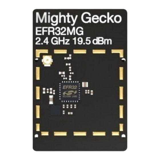
EFR32MG 2.4 GHz 19.5 dBm Radio Board
BRD4154A Reference Manual
The EFR32MG family of Wireless SoCs deliver a high perform-
ance, low energy wireless solution integrated into a small form
factor package.
By combining a high performance 2.4 GHz RF transceiver with an energy efficient 32-bit
MCU, the family provides designers the ultimate in flexibility with a family of pin-compati-
ble devices that scale from 128/256 kB of flash and 16/32 kB of RAM. The ultra-low
power operating modes and fast wake-up times of the Silicon Labs energy friendly 32-
bit MCUs, combined with the low transmit and receive power consumption of the 2.4
GHz radio, result in a solution optimized for battery powered applications.
To develop and/or evaluate the EFR32 Mighty Gecko the BRD4154A Radio Board can
be connected to the Wireless Starter Kit Mainboard to get access to display, buttons and
additional features from Expansion Boards.
silabs.com | Smart. Connected. Energy-friendly.
RADIO BOARD FEATURES
• Wireless SoC:
EFR32MG1P732F256GM32
• CPU core: ARM Cortex-M4 with FPU
• Flash memory: 256 kB + 512 kB
• RAM: 32 kB
• Operation frequency: 2.4 GHz
• Transmit power: 19.5 dBm
• Integrated PCB antenna, UFL connector
(optional).
• Crystals for LFXO and HFXO: 32.768 kHz
and 38.4 MHz.
Rev. 1.0
Advertisement
Table of Contents

Subscribe to Our Youtube Channel
Related Manuals for Silicon Laboratories EFR32MG


Summary of Contents for Silicon Laboratories EFR32MG
- Page 1 EFR32MG 2.4 GHz 19.5 dBm Radio Board BRD4154A Reference Manual The EFR32MG family of Wireless SoCs deliver a high perform- RADIO BOARD FEATURES ance, low energy wireless solution integrated into a small form factor package. • Wireless SoC: EFR32MG1P732F256GM32 By combining a high performance 2.4 GHz RF transceiver with an energy efficient 32-bit •...
-
Page 2: Introduction
BRD4154A Reference Manual Introduction 1. Introduction The EFR32 Mighty Gecko Radio Boards provide a development platform (together with the Wireless Starter Kit Mainboard) for the Silicon Labs EFR32 Mighty Gecko Wireless System on Chips and serve as reference designs for the matching network of the RF inter- face. -
Page 3: Radio Board Connector
BRD4154A Reference Manual Radio Board Connector 2. Radio Board Connector 2.1 Introduction The board-to-board connector scheme allows access to all EFR32MG1 GPIO pins as well as the RESETn signal. For more information on the functions of the available pin functions, we refer you to the EFR32MG1 Datasheet. 2.2 Radio Board Connector Pin Associations The figure below shows the pin mapping on the connector to the radio pins, to the I/O Expander pins (shown in brackets) and their function on the Wireless Starter Kit Mainboard. -
Page 4: Radio Board Block Summary
BRD4154A Reference Manual Radio Board Block Summary 3. Radio Board Block Summary 3.1 Introduction This section gives a short introduction to the blocks of the BRD4154A Radio Board. 3.2 Radio Board Block Diagram The block diagram of the BRD4154A Radio Board is shown in the figure below. EFM8 I/O Expander Connector... -
Page 5: Inverted-F Antenna
BRD4154A Reference Manual Radio Board Block Summary For detailed description of the matching network see Chapter 4.2.1 Description of the 2.4 GHz RF Matching. 3.3.5 Inverted-F Antenna The BRD4154A Radio Board includes a printed Inverted-F antenna (IFA) tuned to have close to 50 Ohm impedance at the 2.4 GHz band. -
Page 6: Rf Section
BRD4154A Reference Manual RF Section 4. RF Section 4.1 Introduction This section gives a short introduction to the RF section of the BRD4154A. 4.2 Schematic of the RF Matching Network The schematic of the RF section of the BRD4154A Radio Board is shown in the following figure. 2.4 GHz Inverted-F Matching... -
Page 7: Inverted-F Antenna
BRD4154A Reference Manual RF Section 4.5 Inverted-F Antenna The BRD4154A Radio Board includes an on-board printed Inverted-F Antenna tuned for the 2.4 GHz band. Due to the design restric- tions of the Radio Board the input of the antenna and the output of the matching network can't be placed directly next to each other thus a 50 Ohm transmission line was necessary to connect them. -
Page 8: Mechanical Details
BRD4154A Reference Manual Mechanical Details 5. Mechanical Details The BRD4154A EFR32 Mighty Gecko Radio Board is illustrated in the figures below. PAVDD Supply DC-DC Filtering Inductor DC-DC & Supply Filter Caps. 30 mm EFR32xx Frame of Optional Shielding 45 mm Figure 5.1. -
Page 9: Emc Compliance
BRD4154A Reference Manual EMC Compliance 6. EMC Compliance 6.1 Introduction Compliance of the fundamental and harmonic levels is tested against the following standards: • 2.4 GHz: • ETSI EN 300-328 • FCC 15.247 6.2 EMC Regulations for 2.4 GHz 6.2.1 ETSI EN 300-328 Emission Limits for the 2400-2483.5 MHz Band Based on ETSI EN 300-328 the allowed maximum fundamental power for the 2400-2483.5 MHz band is 20 dBm EIRP. -
Page 10: Rf Performance
BRD4154A Reference Manual RF Performance 7. RF Performance 7.1 Conducted Power Measurements During measurements the BRD4154A Radio Board was attached to a Wireless Starter Kit Mainboard which was supplied by USB. The voltage supply for the Radio Board was 3.3 V. 7.1.1 Conducted Measurements in the 2.4 GHz band The BRD4154A board was connected directly to a Spectrum Analyzer through its UFL connector (the R1 resistor (0 Ohm) was removed and a 0 Ohm resistor was soldered to the R2 resistor position). -
Page 11: Radiated Power Measurements
BRD4154A Reference Manual RF Performance 7.2 Radiated Power Measurements During measurements the BRD4154A Radio Board was attached to a Wireless Starter Kit Mainboard which was supplied by USB. The voltage supply for the Radio Board was 3.3 V. The radiated power was measured in an antenna chamber by rotating the DUT in 360 degree with horizontal and vertical reference antenna polarizations in the XY, XZ and YZ cuts. -
Page 12: Emc Compliance Recommendations
BRD4154A Reference Manual EMC Compliance Recommendations 8. EMC Compliance Recommendations 8.1 Recommendations for 2.4 GHz ETSI EN 300-328 compliance As it was shown in the previous chapter the radiated power of the fundamental of the BRD4154A EFR32 Mighty Gecko Radio Board complies with the 20 dBm limit of the ETSI EN 300-328 in case of the conducted measurement but due to the high antenna gain the radiated power is higher than the limit by approx. - Page 13 BRD4154A Reference Manual Revision History 9. Revision History Table 9.1. Document Revision History Revision Number Effective Date Change Description 06.05.2016 Initial release. silabs.com | Smart. Connected. Energy-friendly. Rev. 1.0 | 12...
- Page 14 BRD4154A Reference Manual Board Revisions 10. Board Revisions Table 10.1. BRD4154A Radio Board Revisions Radio Board Revision Description Initial release Added solder jumpers and pulled buttons in to IO-expander. Updated EFR32 part number. Note: The silkscreen marking on the board (e.g. PCBxxxx A00) denotes the revision of the PCB. The revision of the actual Radio Board can be read from the on-board EEPROM.
-
Page 15: Table Of Contents
Table of Contents 1. Introduction ....... . 1 2. Radio Board Connector ......2 2.1 Introduction. - Page 16 9. Revision History ......10. Board Revisions......Table of Contents .
- Page 17 The products are not designed or authorized to be used within any Life Support System without the specific written consent of Silicon Laboratories. A "Life Support System" is any product or system intended to support or sustain life and/or health, which, if it fails, can be reasonably expected to result in significant personal injury or death.
Need help?
Do you have a question about the EFR32MG and is the answer not in the manual?
Questions and answers