Omron S82J Series Product Manual
Switch mode power supply
Hide thumbs
Also See for S82J Series:
- Manual (23 pages) ,
- Instruction manual (2 pages) ,
- Technical information (16 pages)
Table of Contents
Advertisement
Quick Links
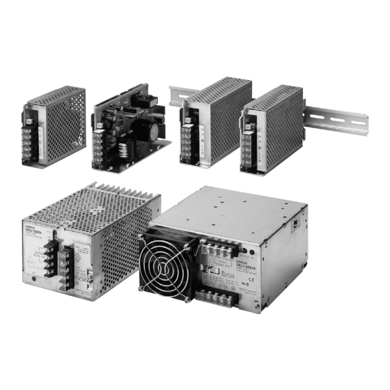
Switch Mode Power Supply
S82J (10/25/50/100/150/300/600-W Models)
Low-cost Global Power Supply with CE
Marking
• Safety standards:
UL: UL508, No.60950-1 Class 2,
CSA: cUL: C22.2 No. 14, cUR: 60950-1 Class 2,
EN60950-1 (=VDE0805 Teil 1), EN50178 (=VDE0160)
• EMC: Conforms to EN61204-3 Class A
• Mounting bracket available for standard models
Front-mounting bracket type
DIN Rail mounting type (except 300 W and 600 W)
Note: Refer to Precautions for Safe Use on page 17.
Model Number Structure
■ Model Number Legend
Note: Not all combinations are possible. Please refer to the list of models in Ordering Information on pages 2 and 3.
S82J -
1
2
1. Power Ratings
010:
10 W
025:
25 W
050:
50 W
100:
100 W
150:
150 W
300:
300 W
600:
600 W
2. Output Voltage
05:
5 V
12:
12 V
15:
15 V
24:
24 V
3
4
3. Configuration
10-/25-/50-/100-/150-W models
A:
Open-frame type, front terminals
D:
Covered type, front terminals
Mounting bracket
None: With mounting bracket
N:
Without mounting bracket
4. Mounting Bracket
None:
Front-mounting bracket type
D:
DIN Rail mounting bracket type
Switch Mode Power Supply
S82J
1
Advertisement
Table of Contents

Subscribe to Our Youtube Channel
Related Manuals for Omron S82J Series


Summary of Contents for Omron S82J Series
- Page 1 Note: Refer to Precautions for Safe Use on page 17. Model Number Structure ■ Model Number Legend Note: Not all combinations are possible. Please refer to the list of models in Ordering Information on pages 2 and 3. S82J - 1. Power Ratings 3.
-
Page 2: Ordering Information
Ordering Information ■ List of Models Note: For details on normal stock models, contact your nearest OMRON representative. Front-mounting Bracket Type Configuration Input Voltage Power ratings Output voltage Output current Front-mounting bracket types (Front terminals) Open-frame type 100 to 240 VAC (free) - Page 3 DIN Rail Mounting Bracket Type Configuration Input Voltage Power ratings Output voltage Output current DIN Rail mounting bracket types (Front terminals) Open-frame type 100 to 240 VAC (free) 10 W S82J-01005AD 12 V S82J-01012AD 15 V 0.7 A S82J-01015AD 24 V 0.5 A...
-
Page 4: Specifications
100 M Ω min. (between all outputs and all inputs/ PE terminals) at 500 VDC Insulation resistance Vibration resistance 10 to 55 Hz, 0.375-mm single amplitude for 2h each in X, Y, and Z directions , 3 times each in ± X, ± Y, ± Z directions Shock resistance... -
Page 5: Block Diagrams
Refer to the Overload Protection section on page 10 for details. 2. Do not use the Inverter output for the Power Supply. Inverters with an output frequency of 50/60 Hz are available, but the rise in the internal temperature of the Power Supply may result in ignition or burning. - Page 6 Control circuit Detection circuit Overcur- rent de- tection circuit Photocoupler Over- voltage detector Overvoltage protection circuit (5 V only) S82J-10024@@ (100 W, 24-V Output) Fuse (5 A) AC(L) DC Output Input Noise filter −V AC(N) Rectification Inrush current Smoothing...
- Page 7 Photocoupler Overvoltage detection circuit Photocoupler Note: Short-circuit the input voltage selector terminals if the input is 100 to 120 VAC. Keep the terminals open if the input is Parallel operation selector 200 to 230 VAC. S82J-60024@ (600 W) Fuse Rectification and...
- Page 8 2. AC Input Terminals: Connect the input lines to these terminals. AC (L) Note: 1. The fuse is located on the (L) side. It is NOT user replaceable. AC (N) −V 2. For DC input (10-W, 25-W models), use the (L) −V...
-
Page 9: Engineering Data
(1 m /min) (Side mounting) Natural cooling (Side mounting) Ambient temperature (°C) Ambient temperature (°C) Note: Provide a minimum clearance of 20 mm between the Power Supplies. 600-W Model Single Operation Parallel Operation Standard Mounting 20 mm min. 20 mm min. -
Page 10: Overload Protection
To reset the S82J, turn OFF the power, leave the S82J for at least three minutes if it is a 600-W model or at least 90 seconds if it is a 300-W model, and then turn it back ON again. - Page 11 Dimensions Note: All units are in millimeters unless otherwise indicated. Open-frame type and covered type have the same dimensions. ■ Front-mounting Bracket Type Mounting Holes S82J-010@@@ (10 W) (Surface Screw Mounting) 12 max. 90± Side Mounting Output indicator (Green) Two, M3...
- Page 12 VOLTAGE SELECT SHORT 100-120V OPEN 200-230V SHORT BAR OPERATION OMRON Corporation MADE IN JAPAN PARALLEL SINGLE 50±0.5 120± 150± Four, M4 holes (depth: 8 max.) 150±0.5 Bottom Mounting Four, 4.5 dia. 100± 100±0.5 150±0.5 150± S82J Switch Mode Power Supply...
- Page 13 Using the Mounting Bracket Attach the mounting bracket to the panel and 15±0.2 loosely tighten the two screws. Insert the projected parts of the bracket (b) to the square holes of the power supply (a). Then securely tighten the screws. Two, 3.5 dia.
- Page 14 300-W and 600-W Models Note: A mounting bracket is included with the S82J-30024 and S82J-60024, but not with the S82J-30024N and S82J-60024N. Front-mounting Bracket Dimensions with Mounting Brackets Attaching the Mounting Brackets For 300-W Models (S82Y-J30F) For 300-W Models For 300-W Models 10 dia.
- Page 15 ■ DIN Rail Mounting Bracket Type S82J-010@@@D (10 W) 7 max. 12 max. (Sliding: 9 max.) S82J-025@@@D (25 W) 7 max. 12 max. (Sliding: 9 max.) S82J-050@@@D (50 W) 7 max. 12 max. (Sliding: 9 max.) S82J-10024@D 7 max. 12 max.
- Page 16 Bracket Three, M4 t = 1.6 Note: These Front-mounting brackets cannot be used with S82J 100-W (5, 12, or 15-V) or 150-W models. ■ DIN Rail Mounting Bracket (Order Separately) Can be used with 10-W to 150-W Front-mounting bracket models.
-
Page 17: Safety Precautions
Do not disassemble, modify, or repair the Product or touch the interior of the Product. The input voltage can be switched between 100 and 200 V by Minor burns may occasionally occur. Do not touch the shorting or opening the input voltage selection terminals. Set the Product while power is being supplied or immediately required voltage as shown below. -
Page 18: Parallel Operation
Set the parallel operation selector to PARALLEL if the Units are in parallel operation and make sure that the thickness and the length of all wires connected to the load are the same to ensure that the wires will have no voltage drop differences. - Page 19 S82J Switch Mode Power Supply...
- Page 20 CONTRACT, WARRANTY, NEGLIGENCE, OR STRICT LIABILITY. In no event shall the responsibility of OMRON for any act exceed the individual price of the product on which liability is asserted. IN NO EVENT SHALL OMRON BE RESPONSIBLE FOR WARRANTY, REPAIR, OR OTHER CLAIMS REGARDING THE...
Need help?
Do you have a question about the S82J Series and is the answer not in the manual?
Questions and answers