Omron S8VK-G Series Manual
Switch mode power supply
Hide thumbs
Also See for S8VK-G Series:
- Instruction manual (2 pages) ,
- Instruction manual (2 pages) ,
- Manual (71 pages)
Table of Contents
Advertisement
New Product
Switch Mode Power Supply
S8VK-G
Reliable and Easy Operation-Worldwide Power Supply
Resistant in tough environments
Easy and fast installation
The most compact class on the market
• Universal input for worldwide applications:
100 to 240 VAC (85 to 264 VAC)
• DC input can be available: 90 to 350 VDC
• Possible for 2-phase input usage.
• Wide operation temperature range: –40 to 70 °C
• Power Boost function at 120%
• Safety standards:
UL508/60950-1, CSA C22.2 No. 107.1/60950-1
EN50178, EN60950-1.
Lloyd's standards, EN60204-1 PELV
Safety of Power Transformers: EN61558-2-16
• ANSI/ISA 12.12.01 (excluding 480-W models)
• CSA C22.2 No.213 (excluding 480-W models)
• 15-W,30-W, and 60-W models conform to
UL Class 2 output Standards
• EMS: EN 61204-3
EMI: EN 61204-3 Class B
• Three years Warranty *1
*1. Refer to Period and Terms of Warranty on page 22.
(15/30/60/120/240/480-W Models)
!
Refer to Safety Precautions for All Power Supplies and Safety
Precautions on page 17.
1
Advertisement
Table of Contents

Related Manuals for Omron S8VK-G Series


Summary of Contents for Omron S8VK-G Series
- Page 1 New Product Switch Mode Power Supply S8VK-G (15/30/60/120/240/480-W Models) Reliable and Easy Operation-Worldwide Power Supply Resistant in tough environments Easy and fast installation The most compact class on the market • Universal input for worldwide applications: 100 to 240 VAC (85 to 264 VAC) •...
-
Page 2: Ordering Information
24: 24 V 120: 120 W 48: 48 V 240: 240 W 480: 480 W Ordering Information Note: For details on normal stock models, contact your nearest OMRON representative. Power ratings Input voltage Output Voltage Output current Boost Current Model number 3.6 A... - Page 3 S8VK-G030@@: 350 VDC min, 4 A *11. Clamp filter “ZCAT2035-0930” manufactured by TDK Corporation. or equivalent should be installed in the cable connected to the input - output terminals of S8VK-G series. Noise filter “FN2080-10-06” manufactured by SCHAFFNER Corporation. or equivalent should be connected to the Input terminals of S8VK-G series.
- Page 4 S8VK-G12024: 350 VDC min, 5 A *11. Clamp filter “ZCAT2035-0930” manufactured by TDK Corporation. or equivalent should be installed in the cable connected to the input - output terminals of S8VK-G series. Noise filter “FN2080-10-06” manufactured by SCHAFFNER Corporation. or equivalent should be connected to the Input terminals of S8VK-G series.
- Page 5 S8VK-G480@@: 350 VDC min, 12 A *11. Clamp filter “ZCAT2035-0930” manufactured by TDK Corporation. or equivalent should be installed in the cable connected to the input - output terminals of S8VK-G series. Noise filter “FN2080-10-06” manufactured by SCHAFFNER Corporation. or equivalent should be connected to the Input terminals of S8VK-G series.
- Page 6 S8VK-G Connections Block Diagrams S8VK-G015@@ (15 W) Fuse: 250 VAC 3.15 A HBC AC (L) INPUT Noise filter DC OUTPUT −V AC (N) Rectifier/ Inrush Smoothing Rectifier −V current smoothing circuit protection circuit Drive control circuit Voltage detection circuit Overcurrent Overvoltage detection circuit detection circuit...
- Page 7 S8VK-G S8VK-G12024 (120 W) Fuse: 250 VAC 5.0 A HBC AC (L) INPUT DC OUTPUT Noise filter −V AC (N) −V Rectifier Harmonic current Inrush current Smoothing Rectifier/smoothing circuit suppression circuit protection circuit (Power factor improvement) circuit −V Drive control circuit Voltage detection circuit...
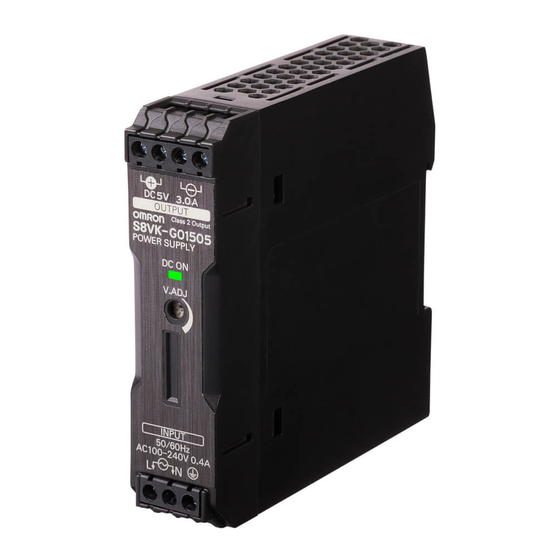
- Page 8 S8VK-G Construction and Nomenclature Nomenclature 15-W Models 30-W Models 60-W Models S8VK-G015@@ S8VK-G030@@ S8VK-G060@@ 120-W Models 240-W Models 480-W Models S8VK-G12024 S8VK-G240@@ S8VK-G480@@ Name Function Connect the input lines to these terminals. *1 Input terminals (L), (N) Protective Earth terminal (PE) Connect the ground line to this terminal.
-
Page 9: Engineering Data
S8VK-G Engineering Data Derating Curve 15, 30, 240 W (S8VK-G015@@, S8VK-G030@@, S8VK-G240@@) 120 W (S8VK-G12024) −40 −25 −10 0 10 20 −40 −25 −10 0 10 20 30 40 50 60 70 80 30 40 50 60 70 80 Ambient temperature (°C) Ambient temperature (°C) Note: 1. -
Page 10: Overvoltage Protection
S8VK-G Mounting Overvoltage Protection Consider the possibility of an overvoltage and design the system so (B) Face-up mounting (A) Standard (Vertical) mounting that the load will not be subjected to an excessive voltage even if the feedback circuit in the Power Supply fails. If an excessive voltage that is approximately 130% of the rated voltage or more is output, the output voltage is shut OFF. -
Page 11: Reference Value
S8VK-G Two phases application for Single phase models For All Single phase Models, S8VK-G Basically OMRON single phase power supply can be used on two- phases of a 3–phase-system when some of conditions satisfy like below. 1. The supplying voltage is below the maximum rated input. - Page 12 S8VK-G Dimensions (Unit: mm) S8VK-G015@@ (15 W) 22.5 ±1 ±1 75.4 ±1 5.08 Rail Stopper (Sliding: 10 max.) S8VK-G030@@ (30 W) ±1 ±1 75.4 ±1 7.62 Rail Stopper (Sliding: 10 max.) S8VK-G060@@ (60 W) ±1 ±1 75.4 ±1 7.62 Rail Stopper (Sliding: 10 max.)
- Page 13 S8VK-G S8VK-G12024 (120 W) 122.2 ±1 117.8 ±1 6.35 112.2 104.6 ±1 6.35 Rail Stopper (10) 19.8 (Sliding: 7.5 max.) S8VK-G240@@ (240 W) ±1 145.6 ±1 6.35 104.6 ±1 6.35 (10) Rail Stopper 19.8 (Sliding: 7.5max.) S8VK-G480@@ (480 W) ±1 145.6 ±1 ±1...
- Page 14 S8VK-G DIN Rail (Order Separately) Note: All units are in millimeters unless otherwise indicated. Mounting Rail (Material: Aluminum) PFP-100N PFP-50N 7.3 ± 0.15 35 ± 27 ± 0.15 15(5) * 1,000 (500) * * Values in parentheses are for the PFP-50N. Mounting Rail (Material: Aluminum) PFP-100N2 35 ±...
-
Page 15: Mounting Brackets
S8VK-G Mounting Brackets Name Model Front-mounting bracket (for 15, 30 and 60 W models) S82Y-VS10F Front-mounting bracket (for 120, 240 and 480 W models) S82Y-VK10F Side-mounting bracket (for 15 W models) S82Y-VK15P Side-mounting bracket (for 30 and 60 W models) S82Y-VS10S Side-mounting bracket (for 120 W models) S82Y-VK10S... - Page 16 S8VK-G Type Model Dimensions Appearance Left-side mounting Right-side mounting ±0.1 4.5 dia. Side-mounting ±0.1 bracket S82Y-VS10S (For 30 and 60 W models) ±0.1 t = 2.0 Left-side mounting Right-side mounting 15.5 ±0.1 ±0.1 4.5 dia. ±0.1 Side-mounting bracket S82Y-VK10S ±0.1 (For 120 W Left-side mounting Right-side mounting...
-
Page 17: Safety Precautions
S8VK-G Safety Precautions Warning Indications Indicates a potentially hazardous situation which, if not avoided, may CAUTION result in minor or moderate injury or in property damage. Supplementary comments on what to Precautions for do or avoid doing, to use the product Safe Use safely. -
Page 18: Precautions For Safe Use
S8VK-G Precautions for Safe Use Wiring • Connect the ground completely. A protective earthing terminal stipulated in safety standards is used. Electric shock or malfunction may occur if the ground is not connected completely. • Minor fire may possibly occur. Ensure that input and output terminals are wired correctly. •... - Page 19 S8VK-G Installation Environment To dismount the Block, pull down portion (C) with a flat-blade screwdriver and pull out the Block. • Do not use the Power Supply in locations subject to shocks or vibrations. In particular, install the Power Supply as far away as possible from contactors or other devices that are a vibration source.
-
Page 20: Series Operation
S8VK-G Series Operation Parallel Operation Two power supplies can be connected in series. Parallel operation is used when the output current from one Power Supply is insufficient for the load. Power Supplies are connected in Correct parallel to increase the output current. AC (L) The parallel operation of S8VK-G is possible to increase the output −V... -
Page 21: Backup Operation
S8VK-G Backup Operation Backup operation is possible if you use two Power Supplies of the same model. Even if one Power Supplies fails, operation can be continued with the other Power Supply. Make sure that the maximum load does not exceed the capacity of one Power Supply. -
Page 22: Terms Of Warranty
(5) Failures caused by factors that could not be anticipated with the scientific or technical knowledge available when the product was shipped (6) Failures caused by other causes for which OMRON is not responsible, such as natural disasters and other acts of God This warranty is limited to the individual product that was delivered and does not cover any secondary, subsequent, or related damages. -
Page 23: Terms And Conditions Agreement
Data presented in Omron Company websites, catalogs and other materials is provided as a guide for the user in determining suitability and does not constitute a warranty. It may represent the result of Omron’s test conditions, and the user must correlate it to actual application requirements. - Page 24 The Netherlands Hoffman Estates, IL 60169 U.S.A. Tel: (31)2356-81-300/Fax: (31)2356-81-388 Tel: (1) 847-843-7900/Fax: (1) 847-843-7787 © OMRON Corporation 2013-2016 All Rights Reserved. OMRON (CHINA) CO., LTD. OMRON ASIA PACIFIC PTE. LTD. In the interest of product improvement, Room 2211, Bank of China Tower, No.
Need help?
Do you have a question about the S8VK-G Series and is the answer not in the manual?
Questions and answers