Table of Contents
Advertisement
Quick Links
www.ti.com
EVM User's Guide: TPSM64406EVM-4PH
TPSM64406 4-Phase, 36V, Single 12A Output,
Synchronous, Buck Module Evaluation Module
Description
This TPSM64406 evaluation board showcases the
features and performance of multiple TPSM64406
buck DC/DC modules with integrated power
MOSFETs and inductors in a multi-phase, single
output configuration. The EVM provides a single
output capable of loading up to 12A. The output
voltages can be individually programmed to a fixed
3.3V, 5V or adjustable using external feedback
resistors and jumpers.
The default switching frequency at full load is
programmed to 1MHz. The switching mode at the light
load is selectable between FPWM and PFM mode.
Each channel can be enabled or disabled by a jumper
selection. Finally, spread spectrum can be enabled
or disabled by a configuration resistor selection. The
TPSM64406EVM-4PH is designed to demonstrate the
full capabilities of two stacked devices on a single
PCB design.
Features
•
Functional Safety-Capable
–
Documentation available to aid functional safety
system design
•
Versatile dual output voltage or multiphase single
output synchronous buck module
– Integrated MOSFETs, inductor, and controller
– Wide input voltage range of 6.3V to 36V
– Adjustable output voltage from 0.8V to 16V
SLVUCT1 – APRIL 2024
Submit Document Feedback
•
•
•
•
•
•
Applications
•
•
•
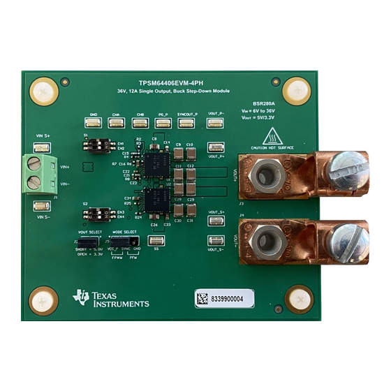
TPSM64406EVM-4PH Board (Top View)
TPSM64406 4-Phase, 36V, Single 12A Output, Synchronous, Buck Module
Copyright © 2024 Texas Instruments Incorporated
– 6.5mm × 7.0mm × 2mm over-molded package
– –40°C to 125°C junction temperature range
– Negative output voltage capability
Ultra-high efficiency across the full load range
– Peak efficiency of 94%+
– External bias option for improved efficiency
– Exposed Pad for low thermal impedance. EVM
θ
= 20 °C/W.
JA
Ultra-low conducted and radiated EMI signatures
– Low-noise package with dual input paths and
integrated capacitors reduces switch ringing
– Input EMI filter with electrolytic capacitor for
parallel damping
– Resistor selectable spread spectrum
– Constant-frequency FPWM mode of operation
– Meets CISPR 11 and 32 Class B emissions
An excellent choice for scalable power supplies
4-layer, 2-oz PCB design
Inherent protection features for robust design
– Precision enable input and open-drain PGOOD
indicator for sequencing, control, and V
– Over-current and thermal shutdown protections
Create a custom design using the TPSM64406
with the
WEBENCH
®
Design
Test and
measurement,
aerospace and defense
Factory automation and control
Buck
and
inverting buck-boost
Description
UVLO
IN
Tool.
power supplies
1
Evaluation Module
Advertisement
Table of Contents

Related Manuals for Texas Instruments TPSM64406EVM-4PH


Summary of Contents for Texas Instruments TPSM64406EVM-4PH
- Page 1 An excellent choice for scalable power supplies or disabled by a configuration resistor selection. The • 4-layer, 2-oz PCB design TPSM64406EVM-4PH is designed to demonstrate the • Inherent protection features for robust design full capabilities of two stacked devices on a single –...
-
Page 2: Kit Contents
Dual 2A / 2A or stackable 4A Enhanced QFN (25) 6.50mm × 7.0mm TPSM64406(-Q1) Dual 3A / 3A or stackable 6A TPSM64406 4-Phase, 36V, Single 12A Output, Synchronous, Buck Module SLVUCT1 – APRIL 2024 Evaluation Module Submit Document Feedback Copyright © 2024 Texas Instruments Incorporated... - Page 3 Remove any jumper when programing the regulation target using an external resistor divider. Populate the external feedback resistor divider. Probe point for power-good indicator. A pullup resistor is connected to VCC. SLVUCT1 – APRIL 2024 TPSM64406 4-Phase, 36V, Single 12A Output, Synchronous, Buck Module Submit Document Feedback Evaluation Module Copyright © 2024 Texas Instruments Incorporated...
-
Page 4: Evm Setup
2-1. Set the load to constant- resistance mode or constant-current mode at 0A before applying input voltage. TPSM64406 4-Phase, 36V, Single 12A Output, Synchronous, Buck Module SLVUCT1 – APRIL 2024 Evaluation Module Submit Document Feedback Copyright © 2024 Texas Instruments Incorporated... -
Page 5: Electronic Load
Figure 3-4. Efficiency, VOUT = 5.0V, AUTO Mode Figure 3-3. Efficiency, VOUT = 5.0V, FPWM Mode SLVUCT1 – APRIL 2024 TPSM64406 4-Phase, 36V, Single 12A Output, Synchronous, Buck Module Submit Document Feedback Evaluation Module Copyright © 2024 Texas Instruments Incorporated... - Page 6 Figure 3-7. Load Regulation, VOUT = 5.0V, FPWM Figure 3-8. Load Regulation, VOUT = 5.0V, AUTO Mode Mode TPSM64406 4-Phase, 36V, Single 12A Output, Synchronous, Buck Module SLVUCT1 – APRIL 2024 Evaluation Module Submit Document Feedback Copyright © 2024 Texas Instruments Incorporated...
- Page 7 Figure 3-14. Load Transient Falling, VOUT = 3.3V, IOUT = 6A to 12A IOUT = 12A to 6A SLVUCT1 – APRIL 2024 TPSM64406 4-Phase, 36V, Single 12A Output, Synchronous, Buck Module Submit Document Feedback Evaluation Module Copyright © 2024 Texas Instruments Incorporated...
- Page 8 Implementation Results www.ti.com Figure 3-15. Bode Plot (VOUT = 5V) Figure 3-16. Bode Plot (VOUT = 3.3V) TPSM64406 4-Phase, 36V, Single 12A Output, Synchronous, Buck Module SLVUCT1 – APRIL 2024 Evaluation Module Submit Document Feedback Copyright © 2024 Texas Instruments Incorporated...
-
Page 9: Emi Performance
Figure 3-17. CISPR 25 Conducted Emissions: 150kHz to 30MHz Figure 3-18. CISPR 25 Conducted Emissions: 30MHz to 108MHz SLVUCT1 – APRIL 2024 TPSM64406 4-Phase, 36V, Single 12A Output, Synchronous, Buck Module Submit Document Feedback Evaluation Module Copyright © 2024 Texas Instruments Incorporated... -
Page 10: Thermal Performance
Figure 3-20. Infrared Thermal Image: VIN = 24V, IOUT = 12A Figure 3-19. Infrared Thermal Image: VIN = 12V, IOUT = 12A TPSM64406 4-Phase, 36V, Single 12A Output, Synchronous, Buck Module SLVUCT1 – APRIL 2024 Evaluation Module Submit Document Feedback Copyright © 2024 Texas Instruments Incorporated... - Page 11 4 Hardware Design Files 4.1 Schematics Figure 4-1 illustrates the EVM schematic. Figure 4-1. EVM Schematic SLVUCT1 – APRIL 2024 TPSM64406 4-Phase, 36V, Single 12A Output, Synchronous, Buck Module Evaluation Module Submit Document Feedback Copyright © 2024 Texas Instruments Incorporated...
-
Page 12: Pcb Layouts
The PCB is 62-mils standard thickness with 2-oz copper on all 6 layers. Figure 4-2. Top 3D View Figure 4-3. Bottom 3D View TPSM64406 4-Phase, 36V, Single 12A Output, Synchronous, Buck Module SLVUCT1 – APRIL 2024 Evaluation Module Submit Document Feedback Copyright © 2024 Texas Instruments Incorporated... - Page 13 Hardware Design Files Figure 4-4. Top Layer Copper Figure 4-5. Layer 2 Copper SLVUCT1 – APRIL 2024 TPSM64406 4-Phase, 36V, Single 12A Output, Synchronous, Buck Module Submit Document Feedback Evaluation Module Copyright © 2024 Texas Instruments Incorporated...
- Page 14 Hardware Design Files www.ti.com Figure 4-6. Layer 3 Copper Figure 4-7. Layer 4 Copper TPSM64406 4-Phase, 36V, Single 12A Output, Synchronous, Buck Module SLVUCT1 – APRIL 2024 Evaluation Module Submit Document Feedback Copyright © 2024 Texas Instruments Incorporated...
- Page 15 Hardware Design Files Figure 4-8. Layer 5 Copper Figure 4-9. Layer 6 Copper SLVUCT1 – APRIL 2024 TPSM64406 4-Phase, 36V, Single 12A Output, Synchronous, Buck Module Submit Document Feedback Evaluation Module Copyright © 2024 Texas Instruments Incorporated...
- Page 16 Hardware Design Files www.ti.com Figure 4-10. Layer Thickness TPSM64406 4-Phase, 36V, Single 12A Output, Synchronous, Buck Module SLVUCT1 – APRIL 2024 Evaluation Module Submit Document Feedback Copyright © 2024 Texas Instruments Incorporated...
- Page 17 Thermal Transfer Printable Labels, 0.650" W PCB Label 0.650 x 0.200 inch THT-14-423-10 Brady x 0.200" H - 10,000 per roll SLVUCT1 – APRIL 2024 TPSM64406 4-Phase, 36V, Single 12A Output, Synchronous, Buck Module Evaluation Module Submit Document Feedback Copyright © 2024 Texas Instruments Incorporated...
- Page 18 3V to 36V, Dual 3A or stackable 6A Power QFN-FCMOD28 TPSM64406 Texas Instruments Module in 6.5mm x 7mm x 2mm Package TPSM64406 4-Phase, 36V, Single 12A Output, Synchronous, Buck Module Evaluation Module SLVUCT1 – APRIL 2024 Submit Document Feedback Copyright © 2024 Texas Instruments Incorporated...
-
Page 19: Additional Information
2. Optimize the design for key parameters such as efficiency, footprint, and cost using the optimizer dial. 3. Compare the generated design with other possible designs from Texas Instruments. The WEBENCH Power Designer provides a customized schematic along with a list of materials with real-time pricing and component availability. - Page 20 STANDARD TERMS FOR EVALUATION MODULES Delivery: TI delivers TI evaluation boards, kits, or modules, including any accompanying demonstration software, components, and/or documentation which may be provided together or separately (collectively, an “EVM” or “EVMs”) to the User (“User”) in accordance with the terms set forth herein.
- Page 21 www.ti.com Regulatory Notices: 3.1 United States 3.1.1 Notice applicable to EVMs not FCC-Approved: FCC NOTICE: This kit is designed to allow product developers to evaluate electronic components, circuitry, or software associated with the kit to determine whether to incorporate such items in a finished product and software developers to write software applications for use with the end product.
- Page 22 www.ti.com Concernant les EVMs avec antennes détachables Conformément à la réglementation d'Industrie Canada, le présent émetteur radio peut fonctionner avec une antenne d'un type et d'un gain maximal (ou inférieur) approuvé pour l'émetteur par Industrie Canada. Dans le but de réduire les risques de brouillage radioélectrique à...
- Page 23 www.ti.com EVM Use Restrictions and Warnings: 4.1 EVMS ARE NOT FOR USE IN FUNCTIONAL SAFETY AND/OR SAFETY CRITICAL EVALUATIONS, INCLUDING BUT NOT LIMITED TO EVALUATIONS OF LIFE SUPPORT APPLICATIONS. 4.2 User must read and apply the user guide and other available documentation provided by TI regarding the EVM prior to handling or using the EVM, including without limitation any warning or restriction notices.
- Page 24 Notwithstanding the foregoing, any judgment may be enforced in any United States or foreign court, and TI may seek injunctive relief in any United States or foreign court. Mailing Address: Texas Instruments, Post Office Box 655303, Dallas, Texas 75265 Copyright © 2023, Texas Instruments Incorporated...
- Page 25 TI products. TI’s provision of these resources does not expand or otherwise alter TI’s applicable warranties or warranty disclaimers for TI products. TI objects to and rejects any additional or different terms you may have proposed. IMPORTANT NOTICE Mailing Address: Texas Instruments, Post Office Box 655303, Dallas, Texas 75265 Copyright © 2024, Texas Instruments Incorporated...
Need help?
Do you have a question about the TPSM64406EVM-4PH and is the answer not in the manual?
Questions and answers