Table of Contents
Advertisement
Quick Links
www.ti.com
EVM User's Guide: TPSM8287A12BBSEVM TPSM8287A12
Evaluation Module for Parallelable, I
Sense 12-A Step-Down Module
Description
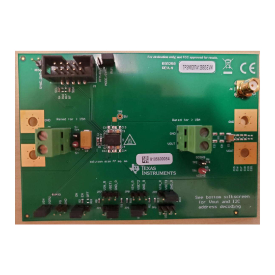
The TPSM8287A12BBSEVM evaluation module
(EVM) facilitates the evaluation of the TPSM8287A12,
a 12-A pin-to-pin compatible step-down power module
2
with an I
C interface, remote sense, and frequency
synchronization in a 4.5 mm × 6.8 mm x 1.8 mm
over molded QFN package. The EVM provides an
adjustable output voltage, with 1% accuracy, between
0.4V and 3.35V from input voltages from 2.7 V to 6 V.
SLUUCV0 – AUGUST 2023
Submit Document Feedback
Features
•
12-A output current power module with integrated
inductor in an over molded QFN package
•
Excellent thermal performance (θ
•
4.5-mm x 6.8-mm power module provides 77-mm
total solution-size with 1.8-mm height
•
Start-up output voltage adjustable through jumpers
to 1 of 59 values
•
Highly accurate output voltage with remote sense
and adjustable control loop compensation
Evaluation Module for Parallelable, I
Copyright © 2023 Texas Instruments Incorporated
2
C Interface, Remote
2
C Interface, Remote Sense 12-A Step-
Description
= 19.5 °C/W)
JA
2
1
Down Module
Advertisement
Table of Contents

Related Manuals for Texas Instruments TPSM8287A12BBSEVM


Summary of Contents for Texas Instruments TPSM8287A12BBSEVM
- Page 1 Description EVM User's Guide: TPSM8287A12BBSEVM TPSM8287A12 Evaluation Module for Parallelable, I C Interface, Remote Sense 12-A Step-Down Module Description Features The TPSM8287A12BBSEVM evaluation module • 12-A output current power module with integrated (EVM) facilitates the evaluation of the TPSM8287A12,...
-
Page 2: Kit Contents
The devices can be operated without the I C interface to provide a high current, fixed-output-voltage power supply. Evaluation Module for Parallelable, I C Interface, Remote Sense 12-A Step- SLUUCV0 – AUGUST 2023 Down Module Submit Document Feedback Copyright © 2023 Texas Instruments Incorporated... -
Page 3: Header Information
Before applying VIN, verify that all 3 jumpers are installed: to JP4 or JP7, JP5 or JP8, and JP6 or JP9. Do not leave the VSETx pins floating. SLUUCV0 – AUGUST 2023 Evaluation Module for Parallelable, I C Interface, Remote Sense 12-A Step- Submit Document Feedback Down Module Copyright © 2023 Texas Instruments Incorporated... -
Page 4: Test Points
GUI or the link symbol at the very bottom left of the GUI. Evaluation Module for Parallelable, I C Interface, Remote Sense 12-A Step- SLUUCV0 – AUGUST 2023 Down Module Submit Document Feedback Copyright © 2023 Texas Instruments Incorporated... - Page 5 Figure 4-1. Thermal Performance (TPSM8287A12BBSEVM, V = 5 V, V = 0.9 V, I = 12A) Figure 4-2 shows the loop response measurement of the TPSM8287A12BBSEVM. SLUUCV0 – AUGUST 2023 Evaluation Module for Parallelable, I C Interface, Remote Sense 12-A Step- Submit Document Feedback Down Module Copyright ©...
-
Page 6: Frequency (Hz)
Figure 4-2. Loop Response Measurement (V = 5 V, V = 0.9 V, I = 12A) Evaluation Module for Parallelable, I C Interface, Remote Sense 12-A Step- SLUUCV0 – AUGUST 2023 Down Module Submit Document Feedback Copyright © 2023 Texas Instruments Incorporated... - Page 7 Hardware Design Files 5 Hardware Design Files 5.1 Schematics Figure 5-1 shows the EVM schematic. The TPSM8287A12BBSEVM uses the TPSM8287A12BBSRDVR IC. 49.9 VOUT VOUT 22µF 22µF 22µF 22µF VOUT 220uF VOUT VOUT VOUT 6.3V 6.3V 6.3V 6.3V 6.3V 6.3V 6.3V...
-
Page 8: Pcb Layouts
Figure 5-5. Internal Layer 2 Figure 5-6. Internal Layer 3 Figure 5-7. Internal Layer 4 Evaluation Module for Parallelable, I C Interface, Remote Sense 12-A Step- SLUUCV0 – AUGUST 2023 Down Module Submit Document Feedback Copyright © 2023 Texas Instruments Incorporated... - Page 9 Hardware Design Files Figure 5-8. Bottom Layer Figure 5-9. Bottom Assembly (Mirrored) SLUUCV0 – AUGUST 2023 Evaluation Module for Parallelable, I C Interface, Remote Sense 12-A Step- Submit Document Feedback Down Module Copyright © 2023 Texas Instruments Incorporated...
-
Page 10: Bill Of Materials (Bom)
Instruments 6 Additional Information Trademarks All trademarks are the property of their respective owners. Evaluation Module for Parallelable, I C Interface, Remote Sense 12-A Step- SLUUCV0 – AUGUST 2023 Down Module Submit Document Feedback Copyright © 2023 Texas Instruments Incorporated... - Page 11 STANDARD TERMS FOR EVALUATION MODULES Delivery: TI delivers TI evaluation boards, kits, or modules, including any accompanying demonstration software, components, and/or documentation which may be provided together or separately (collectively, an “EVM” or “EVMs”) to the User (“User”) in accordance with the terms set forth herein.
- Page 12 www.ti.com Regulatory Notices: 3.1 United States 3.1.1 Notice applicable to EVMs not FCC-Approved: FCC NOTICE: This kit is designed to allow product developers to evaluate electronic components, circuitry, or software associated with the kit to determine whether to incorporate such items in a finished product and software developers to write software applications for use with the end product.
- Page 13 www.ti.com Concernant les EVMs avec antennes détachables Conformément à la réglementation d'Industrie Canada, le présent émetteur radio peut fonctionner avec une antenne d'un type et d'un gain maximal (ou inférieur) approuvé pour l'émetteur par Industrie Canada. Dans le but de réduire les risques de brouillage radioélectrique à...
- Page 14 www.ti.com EVM Use Restrictions and Warnings: 4.1 EVMS ARE NOT FOR USE IN FUNCTIONAL SAFETY AND/OR SAFETY CRITICAL EVALUATIONS, INCLUDING BUT NOT LIMITED TO EVALUATIONS OF LIFE SUPPORT APPLICATIONS. 4.2 User must read and apply the user guide and other available documentation provided by TI regarding the EVM prior to handling or using the EVM, including without limitation any warning or restriction notices.
- Page 15 Notwithstanding the foregoing, any judgment may be enforced in any United States or foreign court, and TI may seek injunctive relief in any United States or foreign court. Mailing Address: Texas Instruments, Post Office Box 655303, Dallas, Texas 75265 Copyright © 2023, Texas Instruments Incorporated...
-
Page 16: Important Notice
TI products. TI’s provision of these resources does not expand or otherwise alter TI’s applicable warranties or warranty disclaimers for TI products. TI objects to and rejects any additional or different terms you may have proposed. IMPORTANT NOTICE Mailing Address: Texas Instruments, Post Office Box 655303, Dallas, Texas 75265 Copyright © 2023, Texas Instruments Incorporated...
Need help?
Do you have a question about the TPSM8287A12BBSEVM and is the answer not in the manual?
Questions and answers