Table of Contents
Advertisement
Quick Links
www.ti.com
EVM User's Guide: TPSM86837EVM
TPSM86837 Buck Module Evaluation Module
Description
The TPSM86837EVM evaluation module (EVM) is
a single, synchronous buck power module providing
1.8V at 8A output from 4.5V to 28V input. The
TPSM86837EVM evaluation module (EVM) helps
designers evaluate the operation and performance
of the TPSM86837 buck regulator. The TPSM86837
is a high efficiency, high-voltage input, easy-to-use
synchronous buck power module, integrates power
MOSFETs, a shielded inductor and basic passives,
minimizing the solution-size.
Features
•
4.5V to 28V input voltage range
SLVUCW0 – JUNE 2024
Submit Document Feedback
•
0.6V to 5.5V output voltage range (default: 1.8V)
•
8A continuous output current capability
•
Supports up to 98% duty operation
•
Eco-mode
•
19-Pin 5.0mm × 5.5mm QFN HotRod
Applications
•
Industrial PC, EPOS, factory automation and
control
•
Multifunction printers, video conference system
•
Monitors, TV, speakers, PC and notebooks,
portable electronics
•
General purposes for 12V,19V, 24V power-bus
supply
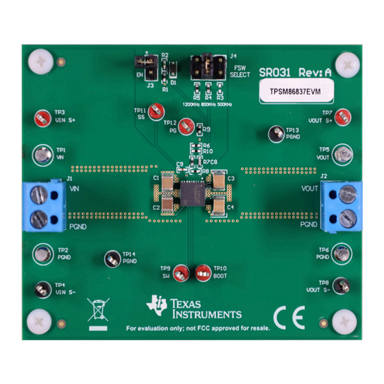
TPSM86837EVM (Top View)
Copyright © 2024 Texas Instruments Incorporated
™
at light load
TPSM86837 Buck Module Evaluation Module
Description
™
package
1
Advertisement
Table of Contents

Related Manuals for Texas Instruments TPSM86837


Summary of Contents for Texas Instruments TPSM86837
- Page 1 ™ package TPSM86837EVM evaluation module (EVM) helps Applications designers evaluate the operation and performance of the TPSM86837 buck regulator. The TPSM86837 • Industrial PC, EPOS, factory automation and is a high efficiency, high-voltage input, easy-to-use control synchronous buck power module, integrates power •...
-
Page 2: Kit Contents
The purpose of TPSM86837EVM is to showcase the typical application of the TPSM86837 device. With the wide operating input voltage range of 4.5V to 28V, the TPSM86837 is designed for systems powered from 12V, 19V, 24V power-bus rails. The device supports up to 8A continuous output current. The output voltage range is from 0.6V to 5.5V. -
Page 3: Input And Output Connections
TP14 GND test point. 2.3 Modifications The evaluation module is designed to provide access to the features of the TPSM86837. Some modifications can be made to this module. 2.3.1 Output Voltage Setpoint To change the output voltage of the EVMs, change the value of resistor R7 (R... -
Page 4: Output Voltage
Transient Response of Internally Compensated DCDC Converters with Feed-forward Capacitor, is helpful when experimenting with a feed-forward capacitor. 2.3.2 Mode Selection TPSM86837 has a MODE pin that can offer two different options of fsw, as shown in below table. Table 2-3. MODE Pin Settings... -
Page 5: Test Setup And Results
Vout = 20 mV/div (1.8V DC o s et) ¡ SW = 20 V/div 1 us/div Figure 3-2. TPSM86837EVM Output Voltage Ripple, V = 24V, I = 8A SLVUCW0 – JUNE 2024 TPSM86837 Buck Module Evaluation Module Submit Document Feedback Copyright © 2024 Texas Instruments Incorporated... - Page 6 Vout = 2 V/div SW = 20 V/div PG = 2 V/div 200 us/div Figure 3-4. TPSM86837EVM Shutdown Relative to EN, I = 8A TPSM86837 Buck Module Evaluation Module SLVUCW0 – JUNE 2024 Submit Document Feedback Copyright © 2024 Texas Instruments Incorporated...
- Page 7 Hardware Design Files 4 Hardware Design Files 4.1 Schematic Figure 4-1 is the schematic for the TPSM86837EVM. Figure 4-1. TPSM86837EVM Schematic Diagram SLVUCW0 – JUNE 2024 TPSM86837 Buck Module Evaluation Module Submit Document Feedback Copyright © 2024 Texas Instruments Incorporated...
-
Page 8: Pcb Layouts
4-8. The top layer contains the main power traces for VIN, VOUT, and ground. Also on the top layer are connections for the pins of the TPSM86837, a large area filled with power ground (PGND), and a small area filled with analog ground (AGND). Most of the signal traces are also located on the top side. The input capacitors and output capacitors are located close to the device . - Page 9 Hardware Design Files Figure 4-6. Middle Layer 1 Figure 4-7. Middle Layer 2 Figure 4-8. Bottom Layer SLVUCW0 – JUNE 2024 TPSM86837 Buck Module Evaluation Module Submit Document Feedback Copyright © 2024 Texas Instruments Incorporated...
- Page 10 TP4, TP8, TP13, TP14 Test Point, Multipurpose, Orange, TH 5011 Keystone 4.5V to 28V Input, 8A Buck Power Module TPSM86837RCG Texas Instruments TPSM86837 Buck Module Evaluation Module SLVUCW0 – JUNE 2024 Submit Document Feedback Copyright © 2024 Texas Instruments Incorporated...
-
Page 11: Additional Information
All trademarks are the property of their respective owners. 6 Reference 1. Texas Instruments, TPSM8683x 4.5V to 28V Input, 8A Synchronous Buck Power Module data sheet SLVUCW0 – JUNE 2024 TPSM86837 Buck Module Evaluation Module Submit Document Feedback Copyright © 2024 Texas Instruments Incorporated... - Page 12 STANDARD TERMS FOR EVALUATION MODULES Delivery: TI delivers TI evaluation boards, kits, or modules, including any accompanying demonstration software, components, and/or documentation which may be provided together or separately (collectively, an “EVM” or “EVMs”) to the User (“User”) in accordance with the terms set forth herein.
- Page 13 www.ti.com Regulatory Notices: 3.1 United States 3.1.1 Notice applicable to EVMs not FCC-Approved: FCC NOTICE: This kit is designed to allow product developers to evaluate electronic components, circuitry, or software associated with the kit to determine whether to incorporate such items in a finished product and software developers to write software applications for use with the end product.
- Page 14 www.ti.com Concernant les EVMs avec antennes détachables Conformément à la réglementation d'Industrie Canada, le présent émetteur radio peut fonctionner avec une antenne d'un type et d'un gain maximal (ou inférieur) approuvé pour l'émetteur par Industrie Canada. Dans le but de réduire les risques de brouillage radioélectrique à...
- Page 15 www.ti.com EVM Use Restrictions and Warnings: 4.1 EVMS ARE NOT FOR USE IN FUNCTIONAL SAFETY AND/OR SAFETY CRITICAL EVALUATIONS, INCLUDING BUT NOT LIMITED TO EVALUATIONS OF LIFE SUPPORT APPLICATIONS. 4.2 User must read and apply the user guide and other available documentation provided by TI regarding the EVM prior to handling or using the EVM, including without limitation any warning or restriction notices.
- Page 16 Notwithstanding the foregoing, any judgment may be enforced in any United States or foreign court, and TI may seek injunctive relief in any United States or foreign court. Mailing Address: Texas Instruments, Post Office Box 655303, Dallas, Texas 75265 Copyright © 2023, Texas Instruments Incorporated...
-
Page 17: Important Notice
TI products. TI’s provision of these resources does not expand or otherwise alter TI’s applicable warranties or warranty disclaimers for TI products. TI objects to and rejects any additional or different terms you may have proposed. IMPORTANT NOTICE Mailing Address: Texas Instruments, Post Office Box 655303, Dallas, Texas 75265 Copyright © 2024, Texas Instruments Incorporated...
Need help?
Do you have a question about the TPSM86837 and is the answer not in the manual?
Questions and answers