Advertisement
Quick Links
www.ti.com
EVM User's Guide: TPSM861252, TPSM861253, TPSM861257
TPSM86125xEVM Step-Down Converter Evaluation
Module
Description
The TPSM86125x is a single, D-CAP3
mode, synchronous buck converter module with input
voltage ranging from 3 V to 17 V and supports up to
1 A continuous current. The TPSM861252 operates
in Eco-mode and the TPSM861253 and TPSM861257
operates in FCCM mode. The TPSM861253 has a
fixed 3.3V Vout, and the TPSM861252/7 has an
adjustable output voltage. The TPSM86125xEVM is
a fully assembled and tested circuit for evaluating the
TPSM86125x converter module.
SLUUCY0A – SEPTEMBER 2023 – REVISED FEBRUARY 2024
Submit Document Feedback
Features
™
control
•
3-V to 17-V input voltage range
•
Adjustable/Fixed 3.3-V output voltage
•
1-A continuous output current
•
Eco/FCCM mode at light load
•
Fast transient D-CAP3
Applications
•
Merchant network and server PSU
•
AC/DC adapters/PSU
•
Factory automation and control
•
Test and measurement
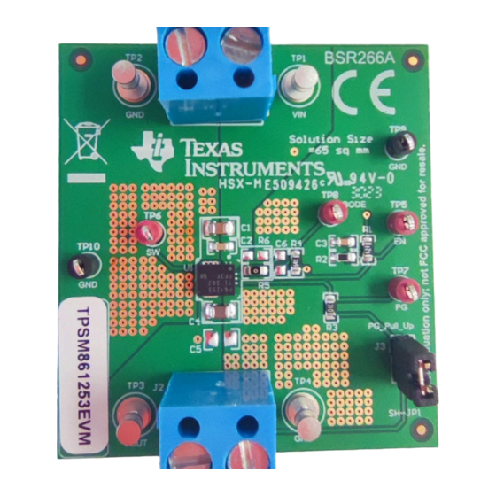
TPSM861253EVM Board (Top View)
Copyright © 2024 Texas Instruments Incorporated
™
control mode
TPSM86125xEVM Step-Down Converter Evaluation Module
Description
1
Advertisement

Related Manuals for Texas Instruments TPSM86125 EVM Series


Summary of Contents for Texas Instruments TPSM86125 EVM Series
- Page 1 AC/DC adapters/PSU TPSM86125x converter module. • Factory automation and control • Test and measurement TPSM861253EVM Board (Top View) SLUUCY0A – SEPTEMBER 2023 – REVISED FEBRUARY 2024 TPSM86125xEVM Step-Down Converter Evaluation Module Submit Document Feedback Copyright © 2024 Texas Instruments Incorporated...
- Page 2 ) Range Output Current (I ) Range TPSM861253EVM = 3.8 V to 17 V 0 A to 1 A TPSM86125xEVM Step-Down Converter Evaluation Module SLUUCY0A – SEPTEMBER 2023 – REVISED FEBRUARY 2024 Submit Document Feedback Copyright © 2024 Texas Instruments Incorporated...
- Page 3 Switch node test point PGOOD test point Test point for loop response measurements TP9, TP10 GND monitor point SLUUCY0A – SEPTEMBER 2023 – REVISED FEBRUARY 2024 TPSM86125xEVM Step-Down Converter Evaluation Module Submit Document Feedback Copyright © 2024 Texas Instruments Incorporated...
- Page 4 1. Apply appropriate input voltage to VIN (J1-1) and GND (J1-2). 2. Apply the loading to VOUT (J2-1) and GND (J2-2). TPSM86125xEVM Step-Down Converter Evaluation Module SLUUCY0A – SEPTEMBER 2023 – REVISED FEBRUARY 2024 Submit Document Feedback Copyright © 2024 Texas Instruments Incorporated...
- Page 5 Vin = 5 V Vin = 12 V -0.8% Vin = 17 V Iout (A) Figure 3-2. TPSM861253EVM Load Regulation SLUUCY0A – SEPTEMBER 2023 – REVISED FEBRUARY 2024 TPSM86125xEVM Step-Down Converter Evaluation Module Submit Document Feedback Copyright © 2024 Texas Instruments Incorporated...
- Page 6 Iout = 1A/div 400us/div Figure 3-4. TPSM861253EVM Load Transient Response, 10% to 90% (0.3-A to 2.7-A) Load Step TPSM86125xEVM Step-Down Converter Evaluation Module SLUUCY0A – SEPTEMBER 2023 – REVISED FEBRUARY 2024 Submit Document Feedback Copyright © 2024 Texas Instruments Incorporated...
- Page 7 Figure 3-7. TPSM861253EVM Shutdown Relative to V = 1 A Figure 3-8 shows the TPSM861253EVM shutdown waveform relative to EN. SLUUCY0A – SEPTEMBER 2023 – REVISED FEBRUARY 2024 TPSM86125xEVM Step-Down Converter Evaluation Module Submit Document Feedback Copyright © 2024 Texas Instruments Incorporated...
- Page 8 Figure 3-9. TPSM861253EVM Output Voltage Ripple, I = 1 A Vout=20mV/div(AC coupled) SW=5V/div 1us/div Figure 3-10. TPSM861253EVM Output Voltage Ripple, I = 0.01 A TPSM86125xEVM Step-Down Converter Evaluation Module SLUUCY0A – SEPTEMBER 2023 – REVISED FEBRUARY 2024 Submit Document Feedback Copyright © 2024 Texas Instruments Incorporated...
- Page 9 4 Hardware Design Files 4.1 Schematic Figure 4-1 is the schematic for the TPSM861253EVM. Figure 4-1. TPSM861253EVM Schematic Diagram SLUUCY0A – SEPTEMBER 2023 – REVISED FEBRUARY 2024 TPSM86125xEVM Step-Down Converter Evaluation Module Submit Document Feedback Copyright © 2024 Texas Instruments Incorporated...
- Page 10 2-oz copper thickness and two internal layers use 1-oz copper thickness. Figure 4-2. TPSM861253EVM Top Assembly Figure 4-3. TPSM861253EVM Top Layer TPSM86125xEVM Step-Down Converter Evaluation Module SLUUCY0A – SEPTEMBER 2023 – REVISED FEBRUARY 2024 Submit Document Feedback Copyright © 2024 Texas Instruments Incorporated...
- Page 11 Hardware Design Files Figure 4-4. TPSM861253EVM Inner1 Layer Figure 4-5. TPSM861253EVM Inner2 Layer SLUUCY0A – SEPTEMBER 2023 – REVISED FEBRUARY 2024 TPSM86125xEVM Step-Down Converter Evaluation Module Submit Document Feedback Copyright © 2024 Texas Instruments Incorporated...
- Page 12 Hardware Design Files www.ti.com Figure 4-6. TPSM861253EVM Bottom Layer TPSM86125xEVM Step-Down Converter Evaluation Module SLUUCY0A – SEPTEMBER 2023 – REVISED FEBRUARY 2024 Submit Document Feedback Copyright © 2024 Texas Instruments Incorporated...
- Page 13 QFN Package 5 Additional Information Trademarks D-CAP3 ™ is a trademark of Texas Instruments. All trademarks are the property of their respective owners. 6 Related Documentation 1. Texas Instruments, TPSM86125x 3V to 17V Input, 1A Synchronous Buck Module in QFN Package...
- Page 14 STANDARD TERMS FOR EVALUATION MODULES Delivery: TI delivers TI evaluation boards, kits, or modules, including any accompanying demonstration software, components, and/or documentation which may be provided together or separately (collectively, an “EVM” or “EVMs”) to the User (“User”) in accordance with the terms set forth herein.
- Page 15 www.ti.com Regulatory Notices: 3.1 United States 3.1.1 Notice applicable to EVMs not FCC-Approved: FCC NOTICE: This kit is designed to allow product developers to evaluate electronic components, circuitry, or software associated with the kit to determine whether to incorporate such items in a finished product and software developers to write software applications for use with the end product.
- Page 16 www.ti.com Concernant les EVMs avec antennes détachables Conformément à la réglementation d'Industrie Canada, le présent émetteur radio peut fonctionner avec une antenne d'un type et d'un gain maximal (ou inférieur) approuvé pour l'émetteur par Industrie Canada. Dans le but de réduire les risques de brouillage radioélectrique à...
- Page 17 www.ti.com EVM Use Restrictions and Warnings: 4.1 EVMS ARE NOT FOR USE IN FUNCTIONAL SAFETY AND/OR SAFETY CRITICAL EVALUATIONS, INCLUDING BUT NOT LIMITED TO EVALUATIONS OF LIFE SUPPORT APPLICATIONS. 4.2 User must read and apply the user guide and other available documentation provided by TI regarding the EVM prior to handling or using the EVM, including without limitation any warning or restriction notices.
- Page 18 Notwithstanding the foregoing, any judgment may be enforced in any United States or foreign court, and TI may seek injunctive relief in any United States or foreign court. Mailing Address: Texas Instruments, Post Office Box 655303, Dallas, Texas 75265 Copyright © 2023, Texas Instruments Incorporated...
- Page 19 TI products. TI’s provision of these resources does not expand or otherwise alter TI’s applicable warranties or warranty disclaimers for TI products. TI objects to and rejects any additional or different terms you may have proposed. IMPORTANT NOTICE Mailing Address: Texas Instruments, Post Office Box 655303, Dallas, Texas 75265 Copyright © 2024, Texas Instruments Incorporated...
Need help?
Do you have a question about the TPSM86125 EVM Series and is the answer not in the manual?
Questions and answers