Table of Contents
Advertisement
Quick Links
Using the TPSM53604EVM, TPSM53603EVM, and
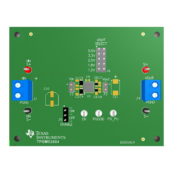
These evaluation boards (EVMs) feature the TPSM53604 (4 A), TPSM53603 (3 A), or TPSM53602 (2 A)
synchronous-buck power module configured for operation with typical 3.8-V to 36-V input bus applications.
The output voltage is set to one of five popular values by using a configuration jumper. The EVM supplies
the full output current rating of the device. Input and output capacitors are included on the board to
accommodate the entire range of input voltage and the selectable output voltages on the EVM. Monitoring
test points are provided to allow measurement of the following:
•
Efficiency
•
Power dissipation
•
Input ripple
•
Output ripple
•
Line and load regulation
•
Transient response
Control test points and jumpers are provided for use of the enable (EN) and power-good (PGOOD)
features of the device. The recommended PCB layout of the EVM maximizes thermal performance and
minimizes output ripple and noise.
NOTE: This EVM user's guide applies to all 3 devices. The only differences in the EVMs are the U1
IC and the silk screen labeling.
1
2
3
4
1
2
3
4
5
6
7
8
9
10
Signal Layer 2
11
12
13
SNVU627B - November 2019 - Revised December 2019
Submit Documentation Feedback
...............................................................................................................
.....................................................................................................
...........................................................................................................
.......................................................................................
..........................................................................................................
...............................................................................................
.............................................................................................
................................................................................
................................................................................
................................................................................
................................................................................................
...........................................................................................................
................................................................................................................
................................................................................................................
................................................................................................................
.................................................................................
...............................................................................................
Using the TPSM53604EVM, TPSM53603EVM, and TPSM53602EVM
Copyright © 2019, Texas Instruments Incorporated
SNVU627B - November 2019 - Revised December 2019
Contents
List of Figures
List of Tables
User's Guide
TPSM53602EVM
3
4
5
6
3
5
5
5
5
5
6
6
7
7
8
8
9
1
Advertisement
Table of Contents

Related Manuals for Texas Instruments TPSM53604EVM


Summary of Contents for Texas Instruments TPSM53604EVM
-
Page 1: Table Of Contents
........................ Signal Layer 3 ................. Bottom Layer Silk Screen (Bottom View) ....................TPSM53604EVM Schematic List of Tables SNVU627B – November 2019 – Revised December 2019 Using the TPSM53604EVM, TPSM53603EVM, and TPSM53602EVM Submit Documentation Feedback Copyright © 2019, Texas Instruments Incorporated... - Page 2 ..................... Test Point Descriptions ........................EVM BOM Trademarks All trademarks are the property of their respective owners. Using the TPSM53604EVM, TPSM53603EVM, and TPSM53602EVM SNVU627B – November 2019 – Revised December 2019 Submit Documentation Feedback Copyright © 2019, Texas Instruments Incorporated...
-
Page 3: Getting Started
EVM. Additionally, the PG_PU pin is present as a convenient point to connect a pullup voltage for the PGOOD signal. SNVU627B – November 2019 – Revised December 2019 Using the TPSM53604EVM, TPSM53603EVM, and TPSM53602EVM Submit Documentation Feedback Copyright © 2019, Texas Instruments Incorporated... -
Page 4: Test Point Descriptions
A 49.9-kΩ resistor is connected to this pin and the PGOOD pin on the EVM. Refer to the product data sheet for absolute maximum ratings associated with the above features. Using the TPSM53604EVM, TPSM53603EVM, and TPSM53602EVM SNVU627B – November 2019 – Revised December 2019 Submit Documentation Feedback Copyright ©... -
Page 5: Performance Data
Figure 2. ENABLE Start-Up Waveform Figure 4. TPSM53604EVM Transient Performance Figure 5. TPSM53603EVM Transient Performance Figure 6. TPSM53602EVM Transient Performance SNVU627B – November 2019 – Revised December 2019 Using the TPSM53604EVM, TPSM53603EVM, and TPSM53602EVM Submit Documentation Feedback Copyright © 2019, Texas Instruments Incorporated... -
Page 6: Evm Board Physical Specifications
EVM board layers. Figure 7. Top Silk Screen (Top View) Figure 8. Top Copper Layer Using the TPSM53604EVM, TPSM53603EVM, and TPSM53602EVM SNVU627B – November 2019 – Revised December 2019 Submit Documentation Feedback Copyright © 2019, Texas Instruments Incorporated... -
Page 7: Signal Layer
EVM Board Physical Specifications www.ti.com Figure 9. Signal Layer 1 Figure 10. Signal Layer 2 SNVU627B – November 2019 – Revised December 2019 Using the TPSM53604EVM, TPSM53603EVM, and TPSM53602EVM Submit Documentation Feedback Copyright © 2019, Texas Instruments Incorporated... -
Page 8: Signal Layer
EVM Board Physical Specifications www.ti.com Figure 11. Signal Layer 3 Figure 12. Bottom Layer Silk Screen (Bottom View) Using the TPSM53604EVM, TPSM53603EVM, and TPSM53602EVM SNVU627B – November 2019 – Revised December 2019 Submit Documentation Feedback Copyright © 2019, Texas Instruments Incorporated... -
Page 9: Tpsm53604Evm Schematic
EVM Board Physical Specifications www.ti.com EVM Schematic Figure 13 shows the TPSM53604EVM schematic. The schematic for the TPSM53603EVM and TPSM53602EVM is identical with the only difference being the U1 IC. Figure 13. TPSM53604EVM Schematic Bill of Materials (BOM) Table 2 shows the EVM BOM. - Page 10 36-V, 2-A, Power Module TPSM53602RDA Not Loaded C1, C2 1206 C7, C8, C10 0805 0402 7343-40 0603 0603 Using the TPSM53604EVM, TPSM53603EVM, and TPSM53602EVM SNVU627B – November 2019 – Revised December 2019 Submit Documentation Feedback Copyright © 2019, Texas Instruments Incorporated...
- Page 11 Changes from Original (November 2019) to A Revision ....................Page ............... • Added the TPSM53603 and TPSM53602 to the user's guide ......................• Added Figure 5 Figure 6 SNVU627B – November 2019 – Revised December 2019 Revision History Submit Documentation Feedback Copyright © 2019, Texas Instruments Incorporated...
- Page 12 STANDARD TERMS FOR EVALUATION MODULES Delivery: TI delivers TI evaluation boards, kits, or modules, including any accompanying demonstration software, components, and/or documentation which may be provided together or separately (collectively, an “EVM” or “EVMs”) to the User (“User”) in accordance with the terms set forth herein.
- Page 13 www.ti.com Regulatory Notices: 3.1 United States 3.1.1 Notice applicable to EVMs not FCC-Approved: FCC NOTICE: This kit is designed to allow product developers to evaluate electronic components, circuitry, or software associated with the kit to determine whether to incorporate such items in a finished product and software developers to write software applications for use with the end product.
- Page 14 www.ti.com Concernant les EVMs avec antennes détachables Conformément à la réglementation d'Industrie Canada, le présent émetteur radio peut fonctionner avec une antenne d'un type et d'un gain maximal (ou inférieur) approuvé pour l'émetteur par Industrie Canada. Dans le but de réduire les risques de brouillage radioélectrique à...
- Page 15 www.ti.com EVM Use Restrictions and Warnings: 4.1 EVMS ARE NOT FOR USE IN FUNCTIONAL SAFETY AND/OR SAFETY CRITICAL EVALUATIONS, INCLUDING BUT NOT LIMITED TO EVALUATIONS OF LIFE SUPPORT APPLICATIONS. 4.2 User must read and apply the user guide and other available documentation provided by TI regarding the EVM prior to handling or using the EVM, including without limitation any warning or restriction notices.
- Page 16 Notwithstanding the foregoing, any judgment may be enforced in any United States or foreign court, and TI may seek injunctive relief in any United States or foreign court. Mailing Address: Texas Instruments, Post Office Box 655303, Dallas, Texas 75265 Copyright © 2019, Texas Instruments Incorporated...
- Page 17 TI products. TI’s provision of these resources does not expand or otherwise alter TI’s applicable warranties or warranty disclaimers for TI products. Mailing Address: Texas Instruments, Post Office Box 655303, Dallas, Texas 75265 Copyright © 2019, Texas Instruments Incorporated...
Need help?
Do you have a question about the TPSM53604EVM and is the answer not in the manual?
Questions and answers