
Related Manuals for Lissmac UNICUT 610


Summary of Contents for Lissmac UNICUT 610
- Page 1 OPERATING MANUAL FLOOR SAW UNICUT 610 LISSMAC Maschinenbau GmbH Lanzstrasse 4 88410 Bad Wurzach, Germany Phone +49 (0) 7564 / 307-0 Fax +49 (0) 7564 / 307-500 lissmac@lissmac.com www.lissmac.com 1/74...
- Page 2 2/74...
- Page 3 Legal notice The operating manual is valid for: LISSMAC floor saw UNICUT 610 Manufacturer: LISSMAC Maschinenbau GmbH Lanzstrasse 4 D - 88410 Bad Wurzach Tel: +49 (0) 7564 / 307 - 0 Fax: +49 (0) 7564 / 307 – 500 lissmac@lissmac.com...
- Page 4 Instructions to the operator in a defined sequence The warning notes contained are not exhaustive. Lissmac cannot foresee every possible hazard scenario. The suitable safety rules and precautions are to be followed as with any other machine, in regards to the working method and operation.
- Page 5 Warning and safety notes used: Read the operating manual Warning of hot surfaces. Wear hearing protection Warning of toxic fumes. Warning of potential injuries due to high pressure Wear eye protection leaks. Warning of electric shock due to damaged power Wear protective gloves lines.
- Page 6 Operating Manual: Internal combustion engine operating manual LISSMAC accepts no responsibility or liability for the completeness of further documentation. Changes and reservations We have taken every effort to ensure that this operating manual is correct and up to date. In order to maintain our technological lead, it may be necessary to make modifications to the product and to its operation without notice.
- Page 7 Notes: 7/74...
-
Page 8: Table Of Contents
Table of contents 1. Features & Benefits ....................... 10 2. General safety notes ...................... 11 2.1. Principle of intended use ....................11 2.2. Organisational Measures....................12 2.3. Choice of personnel and qualification; fundamental obligations ........13 2.4. Safety information relating to the phases of use ............13 2.4.1. - Page 9 7.5. Comfort mode ......................... 50 7.6. Setting the drift correction ....................51 7.7. Safe machine shutdown ....................52 8. Modification options ...................... 53 8.1. Changing from right to left cut ..................53 8.2. Tilt slide box ........................54 8.3. Relocating the slide box....................55 8.4.
-
Page 10: Table Of Contents 1. Features & Benefits
All settings can be made on the central display and all engine values can be read on the display Can be extended with many additional functions using add-on kits The UNICUT 610 fulfils the US EPA Tier 4 final / EU Stage V emissions regulations 10/74... -
Page 11: General Safety Notes
Intended use The LISSMAC floor saw and is designed exclusively for cutting joints in concrete or asphalt. These surfaces can also be mechanically processed in other ways using special extensions. Processing always takes place wet. -
Page 12: Organisational Measures
2.2. Organisational Measures This operating manual must be kept within easy reach for everyone at the place of use. Supplements to the operating manual include general statutory and other binding regulations for preventing accidents and protecting the environment and must be obeyed. Such regulations may also deal with, for example, the handling of hazardous substances, the wearing of personal protective equipment and with road traffic regulations. -
Page 13: Choice Of Personnel And Qualification; Fundamental Obligations
2.3. Choice of personnel and qualification; fundamental obligations Operators must be aged 18 or above and they must be mentally and physically capable of operating the floor saw. All persons must be instructed in the operation and be expressly assigned by the employer with the operation of the floor saw. -
Page 14: Commissioning
2.4.2. Commissioning When fitting the saw blade, protect your hands from sharp edges. Ensure that the substrate on which the cut is made has sufficient bearing capacity All obstacles must be removed from the cutting area. Ensure good lighting in the dark. Visual check of the entire floor saw for any damage and defects. -
Page 15: Relocating The Floor Saw
2.4.4. Relocating the floor saw The floor saw may only be relocated when the saw blade is stationary. Before leaving the operating position on the floor saw, the internal combustion engine must be switched off and the saw blade must be stationary. There is a risk of injury from a rotating saw blade. -
Page 16: Electrical Power
2.5.2. Electrical Power Only use original fuses with the prescribed amperage. The floor saw must be switched off immediately in the event of faults. Electrical work may only be carried out by certified and qualified technical personnel. Regularly inspect and test the electrical equipment of the machinery. Defects such as loose or bare connections or damaged cables must be rectified immediately. -
Page 17: Transport
2.6. Transport Lifting tackle with sufficient carrying capacity must be used when moving with a crane. Examine the lifting tackle for damage before it is used. Appoint an expert instructor for the hoisting work. Only lift the floor saw as described in the operating manual using lifting gear. Only use a suitable transport vehicle with an adequate load capacity. -
Page 18: Device Description
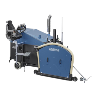
3. DEVICE DESCRIPTION 3.1. Part designation Pos. 1 Comfort seat with seat heating Pos. 8 Saw blade guard (various) Pos. 2 Control unit cover, fuses Pos. 9 Pointer front Pos. 3* Hydraulic steering wheel (accessory) Pos. 10 Pointer rear Pos. 4* Rotating beacon (accessory) Pos. -
Page 19: Connections/Interfaces
3.2. Connections/interfaces Power Pos. 1 Socket water pump 12V (15A) switchable Pos. 2 Socket 1 12V (10A) switchable Pos. 3 Socket 2 12V (10A) switchable Pos. 4 Socket 3 12V (10A) switchable Pos. 5 Socket 4 12V (10A) switchable Pos. 6 Socket 5 12V (10A) constant current Controller Pos. -
Page 20: Technical Data
3.3. Technical Data UNICUT 610 Max. cutting depth 630 mm Max. saw blade diameter 1500 mm Saw blade holder 35 mm (6 x M12 - TK120 mm) Cutting passage Hydraulically stepless 0-52 m/min. Saw blade speed 600-2800 1/min Weight 2150 kg/4740 lbs... -
Page 21: Sound Power Level
The specified value was determined with the maximum saw blade diameter of 1000 mm. The impact may be inversely proportional to the weight of the operator. Hand-arm Vibration total value: Unicut 610 below 2.5 m/s HV(8) Total body Vibration total value: Unicut 610 below 2.5 m/s... -
Page 22: Exhaust Fumes
3.6. Exhaust fumes DANGER Poisonous exhaust gases The exhaust gases of the internal combustion engine contain carbon monoxide. It is invisible, odourless and tasteless, and can cause suffocation. It can quickly accumulate in narrow spaces and stay there for hours, even after the engine has been turned off Never operate machines with internal combustion engines in closed or confined spaces ... -
Page 23: Commissioning
4. COMMISSIONING 4.1. Operating materials Diesel Only low-sulphur diesel fuels according to EN 590 / ASTM D 975 No. Use 2D with a sulphur content <15 mg/kg (so-called ULSD (Ultra Low Sulphur Diesel)). When using other fuels, the emission levels change and the warranty expires. -
Page 24: Water Pump
Diesel AdBlue/DEF tank tank water pump 4.3. Water pump The removable water pump is suspended at the machine and supplies the saw blade with water. The water connection is via GEKA couplings. The pump has a Filter for daily visual control. The pump may only be used for pumping water! There is a risk of explosion if fuel is pumped with it. -
Page 25: Fill In Adblue ® / Def
4.5. Fill in AdBlue / DEF ® CAUTION Skin irritation through contact with DEF Prolonged skin contact may cause skin irritation. In case of eye contact, rinse with plenty of water for 15 minutes. Avoid skin contact Wear safety goggles and gloves ... -
Page 26: Saw Blade Installation/Change (Tool)
4.6. Saw blade installation/change (tool) WARNING Cutting injuries and danger of drawing-in at the rotating saw blade Touching the rotating saw blade can lead to cutting injuries, the severing of limbs and burns. Switch off the engine and remove the ignition key. ... - Page 27 Sequence: 1. Raise the saw head sufficiently and stop the motor. 2. Loosen the cover by turning the two locking screws (pos. 1) 3. Remove the saw blade guard upwards using the handles (Pos 2) 4. Remove the flange nut or screws with the on-board tool and remove the pressure disc (Pos 3) 5.
-
Page 28: Railing And Seating Position
4.7. Railing and seating position Depending on the place of use, cutting direction and cutting process, select a configuration that provides optimum overview to the operator. The seat and the control desk are adjustable in many ways for this purpose. The driver's seat can be mounted on both sides, continuously height-adjusted, rotated and also customised with other modules. -
Page 29: Control Panel
The floor saw is operated via the joystick and the operator can call up various menus on the display, where all relevant data can be displayed and changed. As an option, LISSMAC can also fit a hydraulic steering wheel. Pos. 1 Display Pos. -
Page 30: Joystick
5.1.1. Joystick Joystick position when starting the machine The joystick must be in the neutral position to be able to start and move the machine. Joystick movement Forward (invert with pre-selection page 1 (Pos 4)) Neutral position Right Left Backward (invert with pre-selection page 1 (item 4)) Perform all steering and control commands slowly, carefully and evenly using the joystick! Assignment... -
Page 31: Hmi Control Unit
5.2. HMI control unit Rotary push-button control Turning this button selects input fields and functions and pushing it enables them. Pos. 1 The currently selected field is indicated by a red frame. Pos. 2 "System" direct selection button Pos. 3 “Dashboard”... -
Page 32: Dashboard
5.2.1. Dashboard The dashboard provides the user with the most important information at a glance. 16* 17 Pos.1 Opens Pre-selection page 1 Pos.19 Manual / automatic extraction display Pos.2 Preselection Factor 10 for setting the values Pos.20 Button/display for steering mode 1 / 2 Pos.3 Saw blade depth cut Pos.21... -
Page 33: Depth Preset
5.2.2. Depth preset Presetting the target cutting depth. 2s = “0” Pos. 1 Depth preset direct selection button Pos. 2 Target depth activation Pos. 3 Display of the current cutting depth (since last zero setting) Open page Press the direct selection button for depth preset (Pos. 1). Zeroing the depth If you press and hold the rotary-push button for two seconds, the depth display is set to zero. -
Page 34: Pre-Selection
5.2.3. Pre-selection page 1 Displays and settings for cutting mode. Notice: Not all symbols are always displayed for Pos 9 and 10. The scope depends on the installed and active options. For example, only 9.1 and 10.1 are displayed in the regular depth section. 10.1 10.2 10.3... -
Page 35: Preset
5.2.4. Preset page 2 Displays and default settings for display and features. 8b 8c Settings of joystick The preset is made using the rotary push button. buttons (current selection box is marked with a red border) Press to activate the highlighted selection box. Activated icons are outlined in green. -
Page 36: System
5.2.5. System Displays and settings Settings System settings can be made and messages retrieved in this menu. Pos. 1 Open "Fault memory" see 5.2.6 Pos. 2 Open "Sensor displays" see 5.2.7 Pos. 3 Opens "Panel settings" see 5.2.8 Pos. 4 Opens "Service level"... -
Page 37: Fault Memory
Engine control Pos. 3 Pending fault message SPN (Suspect Parameter Number) DEUTZ SPN/PIN Yellow = warning PIN fault code LISSMAC Red = fault Pos. 4 List of detected faults FMI (Failure Mode Identifier) fault code 1 = GND short circuit Pos. -
Page 38: Sensor Displays
5.2.7. Sensor displays Summary of important system information The "Overview page" menu can be accessed at any time using the Overview button (Pos 2). Pos. 1 Rotary push-button Pos. 9 Engine oil pressure Indicators Pos. 2 Direct selection button Sensor Pos. -
Page 39: Panel Settings
5.2.8. Panel settings The display settings menu allows the operator to adjust the backlight brightness of the display and buttons. Pos. 1 Rotary push-button control Pos. 2 Display settings direct selection button Pos. 3 Display brightness Pos. 4 Keypad brightness Setting the brightness ... -
Page 40: Service
5.2.9. Service This menu is primarily for service technicians. The menu is password-protected. The operator does not need this menu in daily use. Pos. 1 Rotary push-button control Indicators Pos. 2 Softbutton "Service" Pos. 3 Softbutton Level selection 1- 4 Pos. -
Page 41: Transport
6. TRANSPORT 6.1. Transport position Prerequisites Saw blade is removed. Seat with water pump and footboard removed. Hoses are securely lashed or transported separately Plug connections of the control unit are fitted with protective caps. We generally recommend transporting the control unit separately. WARNING Unpredictable change of position of the machine Injuries due to sliding or tilting of the machine... -
Page 42: Procedure In Cutting Or Rapid Traverse Mode
6.2. Procedure in cutting or rapid traverse mode WARNING Risk of injury due to rotating saw blade By touching the rotating saw blade clothes can be pulled in and limbs severed. Any movement of the machine outside the area where cutting work is to be performed must be ... - Page 43 Controls Front Rear Forward (invert with pre-selection page 1 (item 6)) Neutral position Right Left Backward (invert with pre-selection page 1 (item 6)) Traversing in the cutting Move the saw blade over the thumbwheel A to the uppermost position. mode ...
-
Page 44: Relocating Using A Crane
6.3. Relocating using a crane WARNING Suspended loads Injury due to falling parts. Do not stay under hoisted machines or parts. Only use undamaged lifting gear and loading equipment with sufficient load-bearing capacity and length. The machine may only be moved in the transport position. ... -
Page 45: Securing The Machine For Transport
6.4. Securing the machine for transport WARNING Unpredictable change of position of the machine Injuries due to sliding or tilting of the machine Only ever transport the machine in transport position. Secure the machine over the attachment points. Use suitable lifting gear and lashing points. -
Page 46: Operation
7. OPERATION 7.1. Safety General Rules • The floor saw may only be operated by one person. Ensure that other people vacate the work area or set up a barrier. • The operator must not leave his workplace while the engine is running and the saw blade is turning. - Page 47 Always check first, then cut! Check cutting progress according to the latest wiring diagram. Consider tolerance ranges. Consider height differences in the course. Pay attention to unrecorded local changes. Mark the cutting area clearly. Do not cut within the tolerance range.
-
Page 48: Setup And Relocation Of The Floor Saw
7.2. Setup and relocation of the floor saw WARNING Risk of injury due to rotating saw blade By touching the rotating saw blade clothes can be pulled in and limbs severed. Any movement of the machine outside the area where cutting work is to be performed must be done when the tool is not rotating. -
Page 49: Initiating The Cutting Process
7.4. Initiating the cutting process Sequence: 1. Fold tracking pointer down. 2. Put the floor saw in position. 3. Move the joystick to the neutral position 4. Set the engine speed rotary knob to the lowest possible position. 5. Start the engine using the ignition key. 6. -
Page 50: Comfort Mode
7.5. Comfort mode The comfort mode summarises command sequences to reduce the operating effort. Activation Activation is via the control key on selection page 2. Select the desired mode (red frame) with the rotary-push control and activate by pressing. Activated icons are outlined in green. Active Inactive Selection... -
Page 51: Setting The Drift Correction
7.6. Setting the drift correction The saw blade for deep cuts tends to pull the machine to one side. This is completely normal and can easily be corrected via the drift correction to ensure a straight cut. Setting 1. Press and hold the softbutton (pos 1) 2. -
Page 52: Safe Machine Shutdown
7.7. Safe machine shutdown Sequence: Raise blade guard and saw blade Place floor saw in parking position on firm ground. Move the joystick to the neutral position Stop the machine and remove the ignition key. Fold up the pointer ... -
Page 53: Modification Options
8. MODIFICATION OPTIONS 8.1. Changing from right to left cut CAUTION Crushing hazard The guard is turned away from the lifting cylinder during the swivelling process and falls down as a result. Set the locking bolt or Dismantle the saw blade guard before modifying the saw blade ... -
Page 54: Tilt Slide Box
8.2. Tilt slide box Preparation 1. Remove the saw blade. 2. Remove the saw blade protective cover from the floor saw 3. Place the pusher plate over the floor saw in the centre position 4. Suspend the front of the slider box with a crane and secure it against falling down WARNING Suspended loads Danger of injury from falling parts. -
Page 55: Relocating The Slide Box
8.3. Relocating the slide box Preparation 1. Removing the saw blade from the floor saw 2. Remove the saw blade protective cover from the floor saw 3. Place the pusher plate over the floor saw in the centre position 4. Suspend the front end of the slider box with a crane and secure it against falling down WARNING Suspended loads Risk of serious injury from falling parts. -
Page 56: Other Adjustment Options
The switch is located on the right-hand side of the seat shell. 8.6. Hydraulic steering wheel (accessory) A hydraulic steering wheel can also be ordered for travelling. This is fitted by LISSMAC. The steering wheel Accessories Item is infinitely adjustable to the operator in terms of tilt and distance from the seat. -
Page 57: Maintenance
9. MAINTENANCE 9.1. Maintenance WARNING Risk of injury from rotating objects Risk of serious injury from rotating tool. Maintenance and repairs must only ever be carried out when the machine is switched off. Maintenance and repairs may only be carried out by qualified personnel. ... -
Page 58: Fuses And Relays
9.2. Fuses and Relays Main fuse Fuse protection for external 450 A starting terminal Fuse protection control unit 100 A Glow plug fuse protection 60 A Backup fuses Front sockets 40 A Air filter, battery, engine, DEF, 40 A SRC main relay Rear sockets 40 A Main supply relay, fuel pump,... - Page 59 F4.4 Actuators F4.8 SCR exhaust gas purification RELAY K5.1 Main supply K5.3 Starter motor K5.2 Fuel pump K5.4 -empty- Fuses F5.1 Main supply F5.5 Power outputs Lissmac control unit F5.2 Fuel pump F5.6 F5.3 Starter motor F5.7 F5.4 F5.8 59/74...
-
Page 60: Battery
9.3. Battery Type 12V 95Ah - 800A starting current (replacement only by same type) The battery is located at the front right of the machine and is accessible via a maintenance door. If the battery voltage drops below 9V at a time, the controller will be disabled. Check battery voltage regularly. -
Page 61: External Start Terminal
9.4. External start terminal If the battery voltage is not sufficient to start the engine, an external battery can be connected via the external start terminal (+). Determine the cause promptly. Charge the battery regularly or replace it. NOTICE Damage to electronics due to short circuit and residual currents When jump-starting the motor, ensure that the contact clamps only touch the jump-start terminal. -
Page 62: Replacing The Air Filter Cartridge
9.6. Replacing the air filter cartridge Access to the air filter housing is located at the rear of the machine under the cover. Lift the locking mechanism and swivel the tank outwards. The air filter filters the ambient air and prevents foreign matter from penetrating into the combustion chamber. -
Page 63: Maintenance Intervals
9.7. Maintenance intervals Before each use After every weekly monthly Conduct a visual inspection for obvious damage and defects Thoroughly clean the floor saw (depending on the application). Emptying the water collection reservoir in the fuel pre-filter ... -
Page 64: Cleaning The Water Pump Set
9.8. Cleaning the water pump set Check sieve daily before starting work. Do not operate the pump without a sieve insert. Unscrew the cover (pos. 1) and remove the sieve (pos. 2). Clean sieve inserts using water and soft brush. Caution! Do not apply pressure to the fabric. -
Page 65: Troubleshooting
9.10. Troubleshooting The internal combustion engine must be turned off before starting any maintenance or repair work. Secure against accidental restart. Maintenance and service work must only be carried out by qualified technical personnel. NOTICE In the event of cutting problems, check the following points: ... -
Page 66: Regeneration Of The Scr System
9.11. Regeneration of the SCR system SCR function In normal mode, the soot particles spontaneously burn above a certain exhaust gas temperature. maintenance However, soot particles are deposited on the catalyst in the course of time. This requires burning of the catalyst to remove the soot. -
Page 67: Scr Monitoring
9.12. SCR monitoring The SCR system monitors emission-related parameters in accordance with EU/EPA guidelines: -AdBlue fill level -Catalyst function -AdBlue quality -Manipulation detection Engine protection If a serious fault occurs, poor quality of the reducing agent or tampering is detected, or a fault condition is function not resolved, the system automatically initiates a two-stage power reduction. - Page 68 DEF level When the DEF tank is nearly empty (<15%), the operator is warned by displays and prompted to refuel. Fill level Symbol Behaviour DEF symbol Tank System response display AdBlue/DEF Colour Non-EU (EPA) >15% yellow static Level <15% (Tank refill <15% recommended) yellow...
-
Page 69: Maintenance Schedule
9.13. Maintenance Schedule This section is to serve as evidence for the maintenance and service book already supplied. All maintenance and service work must be registered as evidence. Machine/type: Serial number/year of manufacture: Date Maintenance or service work carried out Date/signature 69/74... -
Page 70: Tools
For the best results, the parameters must be correct. With this diagram, the optimum cutting performance can be determined. The prices of the tools can be determined in the LISSMAC sales booklet. This sales booklet can be obtained at any time from the manufacturer. -
Page 71: Warranty
11. WARRANTY The warranty for this machine is 12 months. Warranty is only provided for the wear parts listed below if the wear is not due to operation. Wear parts are parts which undergo operation-dependent wear during the intended use of the machine. These parts have varying service lives, depending on the intensity with which they are used. -
Page 72: Attachment Kits / Upgrades
12. ATTACHMENT KITS / UPGRADES Various functional extensions are available for the machine. Due to the sometimes very specialised areas of application, which are not used by all customers, these are described in separate instructions. Extraction system VACUUM WET 50X Tandem longitudinal cut Grooving unit Core drilling unit... - Page 73 The technical documentation is also stored at this location. In charge of documentation: Head of Construction Series Machine description: The UNICUT 610 is designed exclusively for wet cutting joints in concrete or asphalt surfaces or for mechanical processing of these surfaces. Harmonised standards...
- Page 74 74/74...
Need help?
Do you have a question about the UNICUT 610 and is the answer not in the manual?
Questions and answers