
Related Manuals for Vivo STAND-TS03C


Summary of Contents for Vivo STAND-TS03C
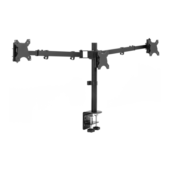
- Page 1 Telescoping Triple Monitor Desk Mount SKU: STAND-TS03C Instruction Manual Assembly Video Available Scan the QR code and follow along with our trained WATCH Product Technicians as they walk you through assembly, start to finish.
- Page 2 If you do not understand these directions, or if you have any doubts about the safety of the installation, please contact our product support team at 309-278-5303 or help@vivo-us.com for further assistance. Check carefully to make sure there are no missing or defective parts. Improper installation may cause damage or serious injury. Do not use this product for any purpose that is not explicitly specified in this manual.
-
Page 3: Package Contents
Package Contents B (x1) A (x1) C (x1) Lower Clamp Pole Upper Clamp D (x1) E (x2) F (x1) Arm Assembly Arm Extensions Support Plate G (x3) I (x1) H (x1) VESA Plates Grommet Plate Grommet Pad J (x1) K (x4) L (x2) Cable Clip Arm Cable Clip... -
Page 4: Included Hardware & Tools
Included Hardware & Tools S-A (x3) S-B (x2) S-C (x1) S-E (x1) S-D (x1) M5x16mm Screw M10x15mm Screw M10 Washer Lock Washer M10 Bolt S-F (x3) S-G (x4) M-A (x12) M-B (x12) M-C (x12) M4x6mm Screw M5x6mm Screw M4x12mm M4x30mm Screw M4 Spacer Thumbscrew T-A (x1) -
Page 5: Assembly Steps
ASSEMBLY STEPS STEP 1 (Option A) Clamp Installation Install Upper Clamp (C) to Pole (A) using M5x16mm Screws (S-A) and the 3mm Allen Wrench (T-A). Assemble Lower Clamp (B) to Upper Clamp (C) using the M10x15mm Screws (S-B) and 5mm Allen Wrench (T-B). Secure the clamp assembly to the desktop by tightening the hand bolts on Lower Clamp (B). - Page 6 STEP 1 (Option B) Grommet Installation Install Pole (A) onto Grommet Plate (I) using the M5x16mm Screws (S-A) and 3mm Allen Wrench (T-A). Remove the adhesive backing from Grommet Pad (H) and place on the bottom of Grommet Plate (I). Install Pole (A) to existing grommet hole using Support Plate (F) with M10 Bolt (S-D), M10 Washer (S-C), and M10 Lock Washer (S-E).
- Page 7 STEP 2 Slide the Arm Assembly (D) and Cable Clip (J) onto the Pole (A) at desired height and tighten the pole bracket bolt using the 6mm Allen Wrench (T-C). STEP 3 Install the Inserts (M) into the Arm Extension (E) by squeezing and pressing the Inserts (M)
- Page 8 ** PLEASE READ ** Optional Safety Stopper The stand features Safety Stoppers to prevent the telescoping arm from being pulled out completely, once assembled. While not required, we strongly recommend the installation of these Stoppers to prevent accidental damage to monitors. Follow steps below for installation of Stoppers. If opting NOT to install Safety Stoppers, please proceed to STEP 4.
- Page 9 CONT’D Line up the Arm Extensions (E) with the arms on the Arm Assembly (D), then press the corner of the Arm Extensions (E) insert into the bushing on the arm. Please Note: The imprinted word “Maximum” should be facing up when intalling Arm Extensions.
- Page 10 CONT’D Apply an even, steady pressure with a motion on the Arm Extension (E) to fully insert. NOTE: There will be a large amount of resistance for approximately 2” until the insert catches on the bushing. 2” After the insert is past the end of the bushing, the arm extension should slide freely within the arm.
- Page 11 STEP 4 Slide the Arm Extension (E) into the arm on the Arm Assembly (D) and tighten the two set screws using the 3mm Allen Wrench (T-A) with arm at the Maximum extension line. WARNING DO NOT have the Arm Extension set beyond the Max Extension mark once the monitors are on.
- Page 12 STEP 5 (Option B) Curved/Recessed Back Monitors Attach the VESA Plates (G) to the monitors using M4x30mm Screws (M-B) with M4 Spacers (M-C) and a Phillips screwdriver. STEP 6 Slide each monitor with VESA Plates (G) onto the VESA brackets and fasten using the M4x6mm Screws (S-F) and Phillips screwdriver.
- Page 13 - Adjusting Your Monitors - Monitor Positioning Adjust the positions of the monitor by sliding the arms in and out to get desired layout. WARNING: DO NOT EXTEND PAST MAX LINE Take caution in adjusting monitor placement. DO NOT pull Arm Extension set beyond the Max Extension mark once the monitors are installed.
- Page 14 - Cable Management - Secure Arm Cable Clips (K) to Arm Assembly (D). Route cables through Arm Cable Clips (K) and Cable Clip (J). - Swivel & Tilt Adjustments - To adjust the swivel or tilt, use 3mm Allen Wrench (T-A) to loosen and tighten center set screw on the VESA bracket.
- Page 15 - Leveling Your Monitors - To level the monitors, use the 5mm Allen Wrench (T-B) to adjust the bolt located behind the VESA bracket. For additional height adjustment, remove you monitor from the stand and use a Phillips screwdriver to remove the 4 screws fastening the VESA bracket to the arms. Shift the VESA brackets as desired then re-tighten the 4 screws.
-
Page 16: Last Updated
LAST UPDATED: 02/20/24 REV1 v1.0 Need Help? Get In Touch Monday-Friday from 7:00am-7:00pm CST help@vivo-us.com www.vivo-us.com 309-278-5303 Chat live with an agent! FOR MORE GREAT VIVO PRODUCTS, CHECK OUT OUR WEBSITE AT: WWW.VIVO-US.COM VIVO-us @vivo_us...
Need help?
Do you have a question about the STAND-TS03C and is the answer not in the manual?
Questions and answers