Table of Contents
Advertisement
Advertisement
Table of Contents

Subscribe to Our Youtube Channel
Related Manuals for Autel MaxiCharger AC Ultra


Summary of Contents for Autel MaxiCharger AC Ultra
- Page 1 MaxiCharger AC Ultra User Manual (EU)
- Page 2 All information, specifications and illustrations in this manual are based on the latest information available at the time of printing. Autel reserves the right to make changes at any time without notice. While information of this manual has been carefully checked for accuracy, no guarantee is given for the completeness and correctness of the contents, including but not limited to the product specifications, functions, and illustrations.
-
Page 3: Table Of Contents
CONTENTS USING THIS MANUAL ........................... 1 ..............................1 ONVENTIONS SAFETY ..............................2 ..............................2 AFETY ESSAGES ............................2 AFETY NSTRUCTIONS ............................3 ISPOSAL NSTRUCTIONS GENERAL INTRODUCTION ........................4 ............................5 RODUCT VERVIEW ................................. 6 N THE ............................7 ECOMMENDED OOLS INSTALLATION ............................ -
Page 4: Using This Manual
Using This Manual This manual describes the installation and use of the MaxiCharger AC Ultra. Prior to installation, read through this manual to be familiarized with the instructions of this MaxiCharger to ensure a successful installation and smooth operations. 1.1 Conventions The following conventions are used. -
Page 5: Safety
2.2 Safety Instructions The safety messages herein cover situations Autel is aware of. Autel cannot know, evaluate or advise you as to all of the possible hazards. You must be certain that any condition or service procedure encountered does not jeopardize your personal safety. -
Page 6: Disposal Instructions
Refer to the vehicle user manual to check if the vehicle releases hazardous or explosive gases when charging. Follow the instructions given in the vehicle user manual before choosing the charging location of the MaxiCharger. Do not direct powerful water jets toward the MaxiCharger. ... -
Page 7: General Introduction
This manual will instruct you on how to install and use this charging station. Intended Use The MaxiCharger AC Ultra is intended for the AC charging of EVs. It is intended for both indoor and outdoor use. DANGER If you use the charging station in any way other than described in this manual or other related documents, possible death, injury and damage to property can occur. -
Page 8: Product Overview
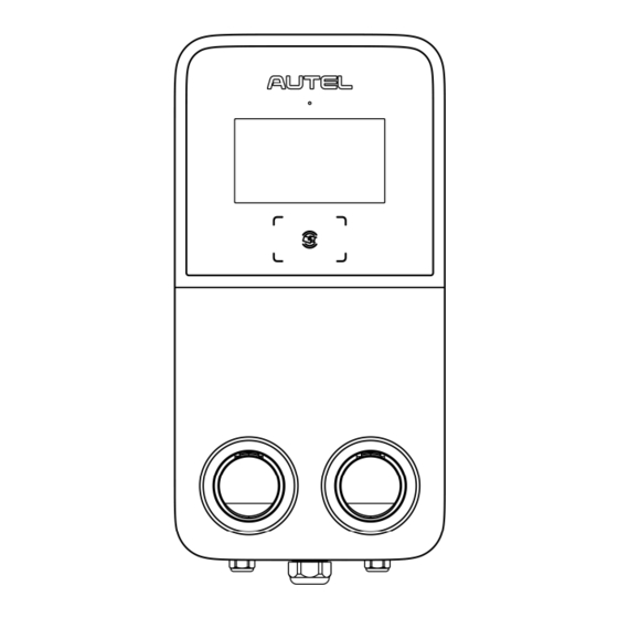
3.1 Product Overview MaxiCharger AC Ultra 1. Ambient Light Sensor — detects ambient brightness 2. Display 3. RFID Reader 4. Status LED (Refer to for details) 8.2 LED Descriptions 5. Socket 6. Product Label 7. Ethernet Cable Port 8. AC Inlet Hole 9. -
Page 9: In The Box
3.2 In the Box Main Kit Charging Station Wall Dock 1 PC 1 PC Screw (M6 x 50) Wall Anchor (For wall-mounting (For wall-mounting only) only) 5 PCS 5 PCS Quick Reference Packing List Guide 1 PC 1 PC Pedestal Kit Expansion Bolt Pedestal (M16 x 150) -
Page 10: Recommended Tools
Tool Kit Drilling Template (For wall-mounting Socket Wrench only) 1 PC 1 PC T10 Screwdriver 1 PC 3.3 Recommended Tools Tape measure Spirit level Pencil 8 mm drilling bit Drill Wire stripper Crimp Connector ... -
Page 11: Installation
Installation 4.1 Prepare for Installation 4.1.1 Choose Location For Wall-mounting: Install the charging station on a flat and vertical surface capable of supporting its weight (e.g. a finished brick or concrete wall). Install the charging station in a location that allows the charging cable to remain within its bending tolerance. -
Page 12: Unpack
5. Ensure that all parts are delivered according to the order. Refer to 3.2 In the Box. 6. Do a visual inspection of the charging station and the parts for damage. In case any damage is found or the parts are not consistent with your order, contact the delivery and Autel support. -
Page 13: Mechanical Installation
4.3 Mechanical Installation There are two ways to mount the charging station: Mounting on a wall Mounting on a pedestal 4.3.1 Mounting on a Wall STEP 1 1. Place the drilling template against the wall, minimum 450 mm above the surface. Then level it using a spirit level. - Page 14 STEP 3 Attach the charging station onto the wall dock by inserting the two mounting screws (B) on the back of the charging station into the two upper mounting holes (A). Slide the charging station downwards to engage the screws. STEP 4 Loosen the two M3 x 8 screws (A) at the bottom of the charging station using the T10 screwdriver and remove the faceplate (B).
- Page 15 STEP 5 Remove the eight M3 x 8 screws using the T10 screwdriver. Set them aside. STEP 6 Flip the maintenance cover up. Then insert two M6 x 50 screws into the two lower holes. Tighten the screws to 5-7 Nm using the socket wrench to secure the charging station.
- Page 16 4.3.2 Mounting on a Pedestal Preparing the Foundation STEP 1 1. Dig a hole with the size of 460 x 300 x 250 mm (L x W x H). 2. Trench and excavate an opening to accommodate the wiring conduit. STEP 2 1.
- Page 17 Drilling Holes 1. Place the drilling template on the foundation, aligning its central hole with the conduit stub-up. Then level the template using a spirit level. 2. Mark the four mounting holes on the foundation. Remove the drilling template. 3. Drill into the holes measuring 18 mm in diameter and 160 mm in depth. Installing the Pedestal STEP 1 Loosen the four M5 x 20 security screws on both sides using the T25 screwdriver to remove the upper and...
- Page 18 STEP 2 1. Place the pedestal onto the foundation, aligning with the conduit stub-up and four mounting holes. 2. Tap the included M16 x 150 expansion bolts into the four mounting holes. Tighten the bolts to 140 Nm to secure the pedestal. Mounting the Wall Dock 1.
- Page 19 Mounting the Charging Station Hang the charging station onto the wall dock by aligning the two mounting screws (A) on the back of the charging station with the two holes (B) of the wall dock. Securing the Charging Station STEP 1 Loosen the two M3 x 8 screws (A) at the bottom of the charging station using the T10 screwdriver and remove the faceplate (B).
- Page 20 STEP 2 Remove the eight M3 x 8 screws using the T10 screwdriver. Set them aside. STEP 3 Flip the maintenance cover up. Then insert two M6 x 25 screws into the two lower holes. Tighten the screws to 5-7 Nm using the socket wrench to secure the charging station.
-
Page 21: Power Supply Wiring
4.4 Power Supply Wiring NOTE Use minimum 16 mm copper wire. Choose based on the power supply available and the distance from the distribution box. 1. Loosen the cable gland at the bottom of the charging station and feed the AC input cable through it. 2. -
Page 22: Connecting To The Internet
4.5 Connecting to the Internet The MaxiCharger AC Ultra can access the Internet via Ethernet cable, cellular network or Wi-Fi. 4.5.1 Via the Ethernet Cable 1. Insert the Ethernet cable with the RJ45 plug through either of the bottom Ethernet cable port (A). -
Page 23: Complete Installation
4.6 Complete Installation 1. Ensure that all installation and wiring are secured and correct. Then flip the maintenance cover down. Reinstall and tighten the eight M3 x 8 screws. 2. Reinstall the faceplate and the two M3 x 8 screws. Tighten them accordingly. The installation is now complete. -
Page 24: Settings
Settings 5.1 Initial Setups When the MaxiCharger is powered on for the first time, it is required to complete the initial setups by the installation engineer. Follow the instructions below: 1. Select the language. Tap Next to continue. 2. Select a local network and enter the Wi-Fi password. If the MaxiCharger has been connected to the Internet via SIM card or Ethernet cable, skip this step. - Page 25 3. Select the time zone. Tap Next to continue or Previous to return to the last page. 4. Select the proper power supply system. This MaxiCharger supports both TN/TT and IT systems. Tap Next to continue or Previous to return to the last page.
-
Page 26: Change The Default Settings
5. Select the maximum input current based on the ratings of the MaxiCharger and local grid capacity. Tap Complete to finish the initial setups or Previous to return to the last page. 5.2 Change the Default Settings Usually, the MaxiCharger has been set up before shipment, so there is no need for further setups other than described above. - Page 27 2. On the Cost Details Screen, tap the upper-left corner to enter the next page. 3. Select Device Maintenance on the screen.
- Page 28 5. On the Device Maintenance Screen, choose a setting to adjust. 6. In some cases where the MaxiCharger uses a third party platform instead of Autel cloud platform, you may need to manually set the parameters by tapping Set Parameters on the Device Maintenance Screen.
-
Page 29: Operation
The display will show that the EV is fully charged. — End the charge session by tapping the RFID card on the RFID reader again or via the Autel Charge app by tapping Stop on the Charging Screen. 2. Remove the charging handle from the charger socket outlet and the EV charging port. -
Page 30: Display Descriptions
6.2 Display Descriptions 6.2.1 Standby Screen 1. Top screen — displays customer support info and a User Guide button (tap to view charging instructions) 2. Middle screen — tap to select a connector 3. Bottom screen — tap to return to the Home page, view the charging costs, and adjust the language The display shows the Standby Screen when the charging station is in idle status, indicating that the charging station is ready for use. - Page 31 6.2.3 Start Charging Screen 6.2.4 Charging Screen The Charging Screen will show the real-time charging progress, current power, charging duration, current cost, as well as volume. If needed, tap the Stop button on this screen to stop charging.
- Page 32 6.2.6 Error Screen The display shows different error messages depending on the error type. Resolve the problem(s) by following the on-screen instructions, contacting Autel technical support or trying another MaxiCharger. Below is an example for the error screen: If the charging handle is not available, the following screen may appear.
-
Page 33: Troubleshooting
Troubleshooting 7.1 Troubleshooting Table Item Problems Solutions The charging station is Check whether the QR code on the charging station is consistent successfully added, but with the QR code on the Quick Reference Guide. If so, make sure the Bluetooth the Bluetooth is enabled on your mobile device;... -
Page 34: Specifications
Specifications 8.1 Product Specifications Item Description AC Power Output Rating 2 x 22 kW AC Power Input Rating 400 V ± 15%, three-phase, 50 Hz Network Type TN, IT, and TT Circuit Breaker 40 A Input Wiring Scheme 400 V AC, three-phase (3P + N + PE) Connector Type IEC 62196 Type 2 socket or socket with shutter Display... -
Page 35: Led Descriptions
Item Description Safety and Compliance IEC/EN 61851-1, EN 62311, EN 62479, IEC/EN 62955 Codes and Standards EMC Class B, UKCA, BSI 7671 Warranty 3 years 8.2 LED Descriptions Description Solid Green: The charging station is in standby mode. Breathing Green: An EV is connected and a charge session has started. - Page 36 Pedestal Front View Pedestal Side View Pedestal Weight: 27.25 kg Pedestal Material: Stainless Steel SUS430...
-
Page 37: Compliance
Compliance The product is in conformity with the following standards and/or other normative documents: EN 301 489-1 V2.2.3 EN 301 489-3 V2.1.1 EN 301 489-17 V3.2.4 EN 301 489-52 V2.1.1 EN 300 328 V2.2.2 EN 300 330 V2.1.1 EN 301 908-1 V13.1.1 EN 301 908-2 V13.1.1 EN 301 908 -13 V13.1.1 EN 301 511 V12.5.1... - Page 38 www.autelenergy.com...
Need help?
Do you have a question about the MaxiCharger AC Ultra and is the answer not in the manual?
Questions and answers