Table of Contents
Advertisement
Quick Links
Advertisement
Table of Contents

Related Manuals for SMAY KWP-OE-EX


Summary of Contents for SMAY KWP-OE-EX
- Page 1 KWP-O- E(S)-EX Technical Documentation Fire Damper https: www.smay.eu...
- Page 2 Technical documentation KWP-O-E(S)-EX 1488 SMAY Sp. z o.o. CSWU: 1488-CPR-0444/W DWU: 003-CPR-2014 DZ: 007-CE-2016 EN 15650:2010 Fire damper type: KWP-O-E-Ex; KWP-O-S-Ex Nominal activation conditions/sensitivity: Pass Closing/opening during the test at the right time Response time/Closure time: Pass Reliability: 50 cycles <120s...
-
Page 3: Table Of Contents
Technical documentation KWP-O-E(S)-EX Version 6.2 SMAY reserves the right to make changes to this document. TABLE OF CONTENT INTRODUCTION ....................3 LEGAL REGULATIONS ..................3 INTENDED USE ....................3 TECHNICAL DESCRIPTION .................. 4 BELIMO ELECTRIC ACTUATORS USED IN KWP-O-ES-EX ......... 9 CONDITIONS OF TRANSPORT AND STORAGE ............ -
Page 4: Introduction
Technical documentation KWP-O-E(S)-EX INTRODUCTION The purpose of technical documentation is to familiarize the user with the intended use, design, operation principle, installation, periodic maintenance and operation of product. LEGAL REGULATIONS Fire dampers KWP-O-E-Ex and KWP-O-S-Ex have: Certificate of Constancy of Performance No. 1488-CPR-0444/W, issued by ITB in Warsaw, with an annex ... -
Page 5: Technical Description
Technical documentation KWP-O-E(S)-EX brick walls with a thickness of 115 mm or more (masonry of solid brick, cellular concrete blocks) masonry walls made of solid bricks or concrete blocks with a thickness of 115 mm ora more." light type walls made from plasterboards on a steel grate having a thickness of 125 mm or more and having fire resistance class EI120 or higher Table 1. - Page 6 Technical documentation KWP-O-E(S)-EX Baffle and also whole automatics controlling the baffle has been merged by ground wire to housing. On housing will be placed grounding clamp, which will be marked with a sticker with the ground symbol. To the clamp should be put a ground cable to effectively ground the damper. The type series of the dampers covers the following dimensions: clear damper width from 200 to 1500 mm (50 mm intervals) and clear damper height from 200 to 1000 mm (50 mm intervals).
- Page 7 Technical documentation KWP-O-E(S)-EX Table 4. KWP-O-S-Ex weight [kg] Width B [mm] KWP-O-S-Ex 1000 1100 1200 1300 1400 1500 11,8 14,0 16,2 18,4 20,6 22,8 13,8 16,5 19,1 21,7 24,3 26,9 29,6 32,0 34,4 36,8 16,0 19,0 22,1 25,0 28,0 31,1 34,1 36,9 40,0...
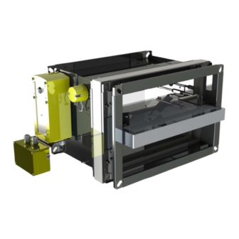
- Page 8 Technical documentation KWP-O-E(S)-EX Figure 1.KWP-O-E-Ex damper Version 6.2 Page 7 z 41 Date of editing: 02.04.2024 r.
- Page 9 Technical documentation KWP-O-E(S)-EX Figure 2. KWP-O-S-Ex damper Version 6.2 Page 8 z 41 Date of editing: 02.04.2024 r.
-
Page 10: Belimo Electric Actuators Used In Kwp-O-Es-Ex
Technical documentation KWP-O-E(S)-EX BELIMO ELECTRIC ACTUATORS USED IN KWP-O-ES-EX Schischek ExMax-BF-15 actuator: Version 6.2 Page 9 z 41 Date of editing: 02.04.2024 r. - Page 11 Technical documentation KWP-O-E(S)-EX ExPro-TT-72 thermal fuse: Belimo BF actuator in EX EDELWEISS housing Dane techniczne Torque -motor 18 Nm -spring 12 Nm Rotation angle 95 °C Running time -motor <120 sec. -spring ±16 sec. (=20°C) Additional Ex-I circuit to connect Intrinsic safe circuit a passive potential free thermostat as a safety sensor, e.g.
- Page 12 Technical documentation KWP-O-E(S)-EX EXBF A version Power supply AC 230 V 50/60 Hz Nominal voltage range AC 198 V…264 V Power consumption -running 8,5W -at rest 3,0W Sizing 11VA EXBF B version Power supply AC 24 V 50/60Hz, DC 24V Nominal voltage range AC 19,2 V …28,8 V DC 21,6 V…28,8 V...
-
Page 13: Conditions Of Transport And Storage
Technical documentation KWP-O-E(S)-EX CONDITIONS OF TRANSPORT AND STORAGE Fire dampers KWP-O-E-Ex and KWP-O-S-Ex should be stored in cardboard boxes and/or on pallets. Dampers should have a pre-protected actuator cardboard box. Fire dampers should be stored indoors, providing protection against atmospheric agents, at a minimum temperature of +5°C. Do not allow mechanical damage of damper, that may be caused e.g. -
Page 14: Installation Technology - Rigid Wall
Technical documentation KWP-O-E(S)-EX 7.1. INSTALLATION TECHNOLOGY – RIGID WALL 7.1.1. INSTALLATION USING MORTAR Make an opening in the wall with the 100 [mm] (acceptable 80 ÷ 120 [mm]) greater than the nominal dimensions of the fire damper = B+100 and H+100. Put the closed fire damper into the installation opening on depth marked by undercuts on the damper body (dimension 60 mm), from one side fix it with suspension Z1, and from other side fix it to the ventilation duct suspended on Z2 suspension. - Page 15 Technical documentation KWP-O-E(S)-EX Figure 3.Installation method of fire dampers KWP-O-Ex in rigid wall Version 6.2 Page 14 z 41 Date of editing: 02.04.2024 r.
-
Page 16: Installation Using Mineral Wool
Technical documentation KWP-O-E(S)-EX 7.1.2. INSTALLATION USING MINERAL WOOL Make an opening in the wall with the 100 [mm] (acceptable 80 ÷ 120 [mm]) greater than the nominal dimensions of the fire damper = B+100 and H+100. Put the closed fire damper into the installation opening on depth marked by undercuts on the damper body (dimension 60 mm), from one side fix it with suspension Z1, and from other side fix it to the ventilation duct suspended on Z2 suspension. - Page 17 Technical documentation KWP-O-E(S)-EX Figure 4.Installation method of fire dampers KWP-O-Ex in rigid wall Version 6.2 Page 16 z 41 Date of editing: 02.04.2024 r.
-
Page 18: Installation Technology - Flexible Wall
Technical documentation KWP-O-E(S)-EX 7.2. INSTALLATION TECHNOLOGY – FLEXIBLE WALL Make an opening in the wall with the dimensions 100 [mm] (acceptable 80 ÷ 120 [mm]) greater than the nominal dimensions of the fire damper = B+100 and H+100. Make a frame of two layers of GKF boards, 12,5 mm thick and the width relative to the width of opening, mounting remembering to carefully seal the contact edges with a mastic: by screws Hilti Firestop Coating CP 673, Promastop-... - Page 19 Technical documentation KWP-O-E(S)-EX Figure 5.Installation method of fire dampers KWP-O-Ex in flexible wall Version 6.2 Page 18 z 41 Date of editing: 02.04.2024 r.
-
Page 20: Installation Technology - Ceiling
Technical documentation KWP-O-E(S)-EX 7.3. INSTALLATION TECHNOLOGY - CEILING Make an opening in the ceiling with the 100 [mm] (acceptable 80 ÷ 120 [mm]) greater than the nominal dimensions of the fire damper = B+100 and H+100. Put the closed fire damper into the ceilng to the depth marked on housing (dimension 60mm) After setting the fire damper as described, with using montage supports, fill the gap between the fire damper and the wall with cement, cement-lime mortar, concrete, or PROMASTOP MG III of production of the PROMAT company. - Page 21 Technical documentation KWP-O-E(S)-EX Figure 7.Installation method of fire dampers in ceiling Version 6.2 Page 20 z 41 Date of editing: 02.04.2024 r.
-
Page 22: Installation Technology - Structures Thicker Than 135 Mm
Technical documentation KWP-O-E(S)-EX 7.4. INSTALLATION TECHNOLOGY – STRUCTURES THICKER THAN 135 mm The KWP-O-E(S)-Ex damper can be installed also in horizontal compartments thicker than length of damper’s body. In this case, ventilation ducts are going to be partially inbuilt in the fire compartment. Figure 8.Installation method of fire dampers in structures thicker than 135 mm Version 6.2 Page 21 z 41... -
Page 23: Installation Technology For Fire Dampers In Batteries
Figure 9. Connection strip SMAY offers four basic types of damper battery systems Arrangement 1 – vertical battery consisting of two fire dampers KWP-O-Ex (Figure 11) Fix the gasket on insulating spacer of one of adjoining fire dampers (position (1) in the Figure 11). - Page 24 Technical documentation KWP-O-E(S)-EX Figure 10. Arrangement 1 - vertical battery consisting of two fire dampers KWP-O-Ex Arrangement 2 - vertical battery consisting of three fire dampers KWP-O-Ex (Figure 12) Fix the gasket on insulating spacer of one of adjoining fire dampers (position (1) in the Figure 12). Put non-combustible mineral wool into recess in upper surface of the fire damper.
- Page 25 Technical documentation KWP-O-E(S)-EX Figure 11. Arrangement 2 - vertical battery consisting of three fire dampers KWP-O-Ex Arrangement 3 - horizontal battery consisting of two fire dampers KWP-O-Ex (Figure 13) Fix the gasket on insulating spacer of one of adjoining fire dampers (position (1) in the Figure 13). Set together the sides of fire damper A and the fire damper B (where the gasket was fixed) and assemble them together on the front and back with use of perforated assembly strips (2) and self-tapping screws M6x16 (3), which should be tightened into the openings in fire damper body.
- Page 26 Technical documentation KWP-O-E(S)-EX Figure 12. Arrangement 3 – horizontal battery consisting of two fire dampers KWP-O-Ex Arrangement 4 – battery consisting of four fire dampers KWP-O-Ex (Figure 14) The assembly of battery consisting of four fire dampers KWP-O-Ex is divided into two steps: Step 1 –...
- Page 27 Technical documentation KWP-O-E(S)-EX Figure 13. Battery made of four dampers KWP-O-Ex Version 6.2 Page 26 z 41 Date of editing: 02.04.2024 r.
- Page 28 Technical documentation KWP-O-E(S)-EX STEP 2: Fix the gasket on insulating spacer of one of adjoining fire dampers (position (2) in the Figure 13). Put non-combustible mineral wool into recess in upper surface of the fire damper C and fire damper D. The thickness of mineral wool should be twice as the thickness of the recess in upper surface of the fire dampers in order to fill the whole free space between the fire dampers C and D and the fire dampers A and B, as shown in (w1).
- Page 29 Technical documentation KWP-O-E(S)-EX Figure 14. Installation of a battery consisting of two fire dampers KWP-O-Ex in vertical arrangement in wall Version 6.2 Page 28 z 41 Date of editing: 02.04.2024 r.
- Page 30 Technical documentation KWP-O-E(S)-EX Figure 15. Installation of a battery consisting of three fire dampers KWP-O-Ex in vertical arrangement in wall Version 6.2 Page 29 z 41 Date of editing: 02.04.2024 r.
- Page 31 Technical documentation KWP-O-E(S)-EX Figure 16. Installation of battery consisting of two fire dampers KWP-O-Ex in horizontal arrangement in wall Version 6.2 Page 30 z 41 Date of editing: 02.04.2024 r.
- Page 32 Technical documentation KWP-O-E(S)-EX Figure 17. Installation of a battery consisting of four fire dampers KWP-O-Ex in wall Version 6.2 Page 31 z 41 Date of editing: 02.04.2024 r.
-
Page 33: Replacing The Thermal Fuse Element
'Installation and Commissioning Protocol - Smoke control dampers'. This protocol should be signed by a person holding a current, personalized certificate or certificate issued by Smay Sp. z o. o. authorizing the installation of KWP-O-E(S)- Ex dampers. A copy of this document should be sent electronically to the manufacturer (www.smay.pl SERVICE AND WARRANTY tab ... - Page 34 Technical documentation KWP-O-E(S)-EX INSTALLATION AND COMMISSIONING PROTOCOL - SMOKE CONTROL DAMPERS Data of the company performing the installation and Device manufacturer commissioning (seal) OBJECT / INSTALLATION LOCATION INSTALLATION AND COMMISSIONING EXECUTION Object Name: …………………………………..…………..…..... KTM-O KTS-O KWP-O ……………………………………………………….…..…….………………………………… KWP-P KWP-Ex KWP-L ……………………………………………………….…..…….…………………………………...
- Page 35 Control Result: Positive / Negative Recommendations: None / as per the remarks above Client Confirmation: Review Contractor Authorization Signature Number (issued by Smay company) Version 6.2 Page 34 z 41 Date of editing: 02.04.2024 r.
-
Page 36: Periodic Maintenance And Servicing Rules
Simultaneously such a device loses the manufacturer's warranty protection in accordance with the OWG All activities related to the replacement or modification of device components can only be carried out by the SMAY Manufacturer's Service or an Authorized SMAY Service/SMAY Service Partner. Elements that have been factory sealed should have intact original seals applied by the SMAY Manufacturer's Service or an Authorized SMAY Service/SMAY Service Partner. - Page 37 Technical documentation KWP-O-E(S)-EX ANNUAL INSPECTION PROTOCOL - SMOKE CONTROL DAMPERS Company performing the inspection (seal) Device manufacturer OBJECT / INSTALLATION LOCATION INSPECTION EXECUTION Date …………………………………………… Nazwa obiektu: …………………………………..…………..…... of execution: … ……………………………………………………….…..…….…… KTM-O KTS-O KWP-O Subject ……………………………………………………….…..…….…… KWP-P KWP-Ex KWP-L of review / Adres obiektu: …………………………...……………..…………...
- Page 38 None / as per remarks above The next inspection should be performed before ………………………..………..………….. 20…………. r. (Month) Confirmation by the Client: Inspection contractor License number Signature (issued by Smay company) Version 6.2 Page 37 z 41 Date of editing: 02.04.2024 r.
- Page 39 Technical documentation KWP-O-E(S)-EX Version 6.2 Page 38 z 41 Date of editing: 02.04.2024 r.
- Page 40 Technical documentation KWP-O-E(S)-EX Version 6.2 Page 39 z 41 Date of editing: 02.04.2024 r.
-
Page 41: Classification Of Dampers For Repair
The manufacturer provides a warranty for the delivered products, on the terms set forth in the Agreement or the General Warranty Conditions of Smay, Sp. z o.o. The warranty does not cover defects resulting from improper storage, transportation, installation, and commissioning, operation, periodic maintenance, service, especially mechanical damage and damage to anti-corrosive coatings. - Page 42 The templates of forms attached to this Technical Documentation (related to installation, commissioning, inspections) are the intellectual property of Smay sp. z o.o. Copying, duplicating, and using them for purposes other than those specified in this Technical and Operating Documentation is prohibited. To maintain the warranty, it is required to fill them out and deliver them to SMAY sp.
Need help?
Do you have a question about the KWP-OE-EX and is the answer not in the manual?
Questions and answers