Table of Contents
Advertisement
Quick Links
Advertisement
Table of Contents

Related Manuals for SMAY KWP-P-E


Summary of Contents for SMAY KWP-P-E
- Page 1 KWP-P-E Technical Fire Damper - rectangular Documentation https: www.smay.eu...
- Page 2 Technical documentation KWP-P-E 1488 SMAY Sp. z o.o. CSWU:1488-CPR-0437/W DWU: 001-CPR-2014 EN 12101-8:2011 Multi-zone fire damper type: KWP-P-E Nominal activation conditions/sensitivity: Automatic starting - Pass Closing/opening during the test at the right time Response time/Closure time: Automatic starting - Pass Reliability: 10 000 cycles.<120S...
-
Page 3: Table Of Contents
Technical documentation KWP-P-E Version 6.00 SMAY reserves the right to make changes to this document. TABLE OF CONTENT INTRODUCTION ....................3 LEGAL REGULATIONS ..................3 INTENDED USE....................3 TECHNICAL DESCRIPTION .................. 4 BELIMO ELECTRIC ACTUATORS USED IN KWP-P-E ..........7 CONDITIONS OF TRANSPORT AND STORAGE ............ -
Page 4: Introduction
– Part 2: Fire dampers, Part 10: Smoke control dampers.” The KWP-P-E fire dampers are classified as tightness class C (housing tightness) devices on the basis of tests carried out according to PN-EN 1751 “Ventilation for buildings. Air terminal devices. Aerodynamic testing of dampers and valves.”... -
Page 5: Technical Description
Baffle is rotating on two steel axles located in housing. Baffle movement is limited in the closed position by a stop bar. KWP-P-E damper is provided with an electric actuator and BLF, BFL, BFN or BF series return spring by BELIMO, constituting the damper’s actuating system having supply voltage AC 230V or AC/DC 24V. After voltage is supplied, the actuator rotates the baffle into the open position. - Page 6 Technical documentation KWP-P-E Table 2. Type series of damper dimension KWP-P-E BEN actuators are used for the damper clear area of P≤ 1,2 [m BEE actuators are used for the damper clear area of 1,2 [m ]< P ≤ 1,3 [m ], and when H ≤...
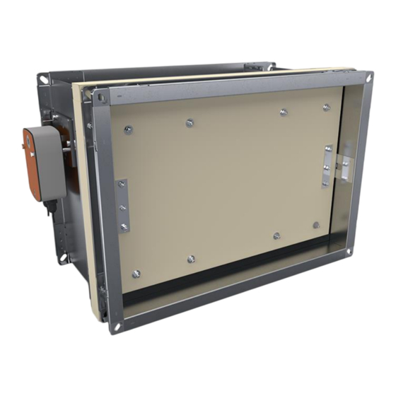
- Page 7 Technical documentation KWP-P-E Figure 1. KWP-P-E damper Version 6.00 Strona 6 z 35 Date of editing: 16.09.2022 r.
-
Page 8: Belimo Electric Actuators Used In Kwp-P-E
1400 65,3 72,8 80,1 87,5 96,2 103,6 1500 69,0 76,9 84,7 92,5 101,5 109,3 BELIMO ELECTRIC ACTUATORS USED IN KWP-P-E Actuator BEN series: • BEN230, • BEN24, • BEN24-ST, • BEN24-SR. where: ST - connection plug SR - analog control Actuator BEE series: •... - Page 9 Technical documentation KWP-P-E Wiring diagram BEN230, BEE230 and BE230: BEN230: BEE230: BE230: Version 6.00 Strona 8 z 35 Date of editing: 16.09.2022 r.
- Page 10 Technical documentation KWP-P-E Wiring diagram BEN24, BEE24 and BE24: BEN24: BEE24: BE24: Version 6.00 Strona 9 z 35 Date of editing: 16.09.2022 r.
- Page 11 Technical documentation KWP-P-E Wiring diagram BEN24-ST, BEE24-ST and BE24-ST: BEN24-ST: BE24-ST: BEE24-ST: Version 6.00 Strona 10 z 35 Date of editing: 16.09.2022 r.
- Page 12 Technical documentation KWP-P-E Wiring diagram BEN24-SR and BEE24-SR: BEN24-SR: BEE24-SR: Technical data: BEN230 BEN24 (-ST) Version 6.00 Strona 11 z 35 Date of editing: 16.09.2022 r.
- Page 13 Dokumentacja techniczno-ruchowa KWP-P-E Technical data: BEE230 BEE24 (-ST) Wersja 1.00 Strona 12 z 35 Data edycji: 16.09.2022 r.
- Page 14 Dokumentacja techniczno-ruchowa KWP-P-E Technical data: BE230 BE24 (-ST) Wersja 1.00 Strona 13 z 35 Data edycji: 16.09.2022 r.
-
Page 15: Conditions Of Transport And Storage
Before installing the fire dampers, make sure that there is no damage, during transport or storage, that could block the baffle. Check that the baffle can be opened and closed (full opening and closing position). To open fire dampers KWP-P-E use the actuator key. -
Page 16: Installation Technology - Rigid Wall
Dokumentacja techniczno-ruchowa KWP-P-E Figure 3. Correct preparation of the damper for installation (using mounting wedge) ATTENTION: The damper must be installed in such way, that the axis of baffle must be in horizontal or vertical position, Damper can not be used as formwork for the wall,... - Page 17 Dokumentacja techniczno-ruchowa KWP-P-E Figure 4.Installation method of fire dampers KWP-O in rigid wall Wersja 1.00 Strona 16 z 35 Data edycji: 16.09.2022 r.
- Page 18 Dokumentacja techniczno-ruchowa KWP-P-E Figure 5. Installation method of the damper in rigid wall with one-sidedly connected self-supporting smoke extract duct. Wersja 1.00 Strona 17 z 35 Data edycji: 16.09.2022 r.
- Page 19 Dokumentacja techniczno-ruchowa KWP-P-E Figure 6. Installation method of the damper in rigid wall with one-sidedly connected self-supporting smoke extract duct connected on both sides. Wersja 1.00 Strona 18 z 35 Data edycji: 16.09.2022 r.
-
Page 20: Installation Technology - Ceiling
Dokumentacja techniczno-ruchowa KWP-P-E 7.2. INSTALLATION TECHNOLOGY - CEILING PROMAT self-supporting duct: Make an opening in the ceiling with the 100 [mm] (acceptable 80 ÷ 120 [mm]) greater than the nominal dimensions of the fire damper = B+100 and H+100. In case of other dimensions than B+100 x H+100, adjust dimensions of mounting brackets. - Page 21 Dokumentacja techniczno-ruchowa KWP-P-E Figure 8. Installation method of fire dampers KWP-O in ceiling with a fire ventilation duct with sealing of cement mortar Figure 9.Proposed dimensions of mounting brackets for installation in a ceiling Actuator under ceiling Actuator above ceiling...
-
Page 22: Installation Technology - Duct
Connection in accordance with the standard of the supplier of the ventilation duct, taking into account the weight of the damper, KWP-P-E damper, Connection stub DX51D-Z275 thickness of 1,5mm with dimensions B+5, H+5 [mm] and of length L (in the... -
Page 23: Installation Technology For Fire Dampers In Batteries
Dokumentacja techniczno-ruchowa KWP-P-E Figure 11. Dimensions of the building partition depending on the high of a damper INSTALLATION TECHNOLOGY FOR FIRE DAMPERS IN BATTERIES The assembly of fire dampers in batteries is possible only after previous delivery of the information (at the stage of ordering) about which fire dampers and in which arrangement (horizontal or vertical) would be installed in a wall, in order to prepare suitable opening for self-tapping screws in the fire damper body. - Page 24 Dokumentacja techniczno-ruchowa KWP-P-E SMAY offers four basic types of damper battery systems. Arrangement 1 – vertical battery consisting of two fire dampers KWP (Figure 11) Fix the gasket on insulating spacer of one of adjoining fire dampers (position (1) in the Figure 11).
- Page 25 Dokumentacja techniczno-ruchowa KWP-P-E Arrangement 2 - vertical battery consisting of three fire dampers KWP (Figure 12) Fix the gasket on insulating spacer of one of adjoining fire dampers (position (1) in the Figure 12). Put non-combustible mineral wool into recess in upper surface of the fire damper. The thickness of mineral wool should be twice as the thickness of the recess in upper surface of the fire damper in order to fill the whole free space between the fire dampers as shown in (w1).
- Page 26 Dokumentacja techniczno-ruchowa KWP-P-E Arrangement 3 - horizontal battery consisting of two fire dampers KWP (Figure 13) Fix the gasket on insulating spacer of one of adjoining fire dampers (position (1) in the Figure 13). Set together the sides of fire damper A and the fire damper B (where the gasket was fixed) and assemble them together on the front and back with use of perforated assembly strips (2) and self-tapping screws M6x10 (3), which should be tightened into the openings in fire damper body.
- Page 27 Dokumentacja techniczno-ruchowa KWP-P-E Arrangement 4 – battery consisting of four fire dampers KWP (Figure 14) The assembly of battery consisting of four fire dampers KWP is divided into two steps: Step 1 – assembly of fire damper A and fire damper B and assembly of fire damper C and fire damper D.
- Page 28 Dokumentacja techniczno-ruchowa KWP-P-E STEP 2: Fix the gasket on insulating spacer of one of adjoining fire dampers (position (2) in the Figure 13). Put non-combustible mineral wool into recess in upper surface of the fire damper C and fire damper D. The...
- Page 29 Dokumentacja techniczno-ruchowa KWP-P-E Figure 4. Installation of a battery consisting of two fire dampers KWP in vertical arrangement in ceiling Wersja 1.00 Strona 28 z 35 Data edycji: 16.09.2022 r.
- Page 30 Dokumentacja techniczno-ruchowa KWP-P-E Figure 58.Installation of a battery consisting of three fire dampers KWP in vertical arrangement in ceiling Wersja 1.00 Strona 29 z 35 Data edycji: 16.09.2022 r.
- Page 31 Dokumentacja techniczno-ruchowa KWP-P-E Figure 69. Installation of battery consisting of two fire dampers KWP in horizontal arrangement in ceiling Wersja 1.00 Strona 30 z 35 Data edycji: 16.09.2022 r.
- Page 32 Dokumentacja techniczno-ruchowa KWP-P-E Figure 20. Installation of a battery consisting of four fire dampers KWP in ceiling Wersja 1.00 Strona 31 z 35 Data edycji: 16.09.2022 r.
- Page 33 Dokumentacja techniczno-ruchowa KWP-P-E Weight of KWP-O-E(S) dampers battery Weight of battery made of two KWP dampers [kg] B[mm] - clear KWP damper width 1000 1100 1200 1300 1400 1500 26,7 31,7 36,6 41,1 50,9 55,9 60,8 65,8 70,9 75,9 90,5...
-
Page 34: Principles Of Maintenance
After installation of the KWP-P-E fire damper, when running the system, it is recommended to carry out regular checks and record them as shown in table below. It is recommended to repeat checks at intervals or at least once every 6 months. - Page 35 Dokumentacja techniczno-ruchowa KWP-P-E In order to check the proper functioning of fire damper, in particular: Check the fire damper without disconnecting the supply voltage from the actuator. The opening and closing test should be carried out by positioning the baffle from control system („open” and „closed”...
-
Page 36: Terms Of Warranty
The warranty period is extended by the duration of the repair. The warranty is valid in the cases described in the OWG. OWG & OWS documents are available on the website www.smay.pl Above terms of warranty apply only in Poland.
Need help?
Do you have a question about the KWP-P-E and is the answer not in the manual?
Questions and answers