Advertisement
Quick Links
Advertisement

Related Manuals for SMAY KWP-O-E


Summary of Contents for SMAY KWP-O-E
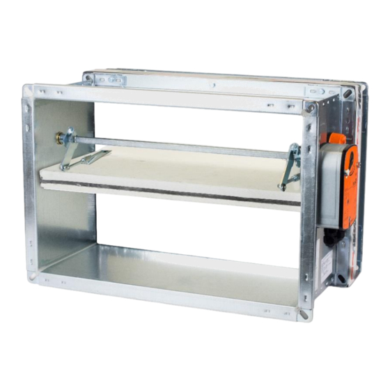
- Page 1 KWP-O- E(S) Installation manual Fire Damper – rectangular https: www.smay.eu...
-
Page 2: Table Of Contents
Installation manual KWP-O-ES Version 6.00 SMAY reserves the right to make changes to this document. TABLE OF CONTENT INSTALLATION TECHNOLOGY ..................2 INSTALLATION TECHNOLOGY – RIGID WALL ............3 INSTALLATION TECHNOLOGY – FLEXIBLE WALL ............ 5 III. INSTALLATION TECHNOLOGY - CEILING ............... 6 INSTALLATION TECHNOLOGY –... -
Page 3: Installation Technology
Check whether the damper baffle could be opened and closed (fully open and closed position). To open fire dampers KWP-O-E use the actuator key. The full opening and closing must proceed smoothly (not stepwise). You must not pull by baffle to open or close fire damper, it could cause lead to permanent damage, not covered by the warranty. -
Page 4: Installation Technology - Rigid Wall
Installation manual KWP-O-ES Figure 2. Correct preparation of the damper for the installation (using mounting wedge) ATTENTION: The damper must be installed in such way, that the axis of baffle must be in horizontal or vertical position, Damper can not be used as formwork for the wall, Ventilation ducts should be installed that they cannot put any load on the damper, their suspension must ensure their full load capacity, The suspensions of the ventilation ducts connected to the dampers batteries must be made in accordance with... - Page 5 Installation manual KWP-O-ES Figure 3.. Installation method of fire dampers KWP-O in rigid wall Version 6.00 Page 4 z 18 Date of editing: 16.09.2022 r.
-
Page 6: Installation Technology - Flexible Wall
Installation manual KWP-O-ES INSTALLATION TECHNOLOGY – FLEXIBLE WALL Make an opening in the wall with the dimensions 100 [mm] (acceptable 80 ÷ 120 [mm]) greater than the nominal dimensions of the fire damper = B+100 i H+100. Make a frame of two layers of GKF boards, 12,5 mm thick and the width relative to the width of opening, remembering to carefully seal the contact edges with a mastic: mounting by screws screws Hilti Firestop Coating... -
Page 7: Installation Technology - Ceiling
Installation manual KWP-O-ES III. INSTALLATION TECHNOLOGY - CEILING Make an opening in the ceiling with the 100 [mm] (acceptable 80 ÷ 120 [mm]) greater than the nominal dimensions of the fire damper = B+100 and H+100. Put the closed fire damper into the ceiling to the depth marked on housing (dimension 60mm) After setting the fire damper as described, with using montage supports, fill the gap between the fire damper and the wall with cement, cement-lime mortar, concrete. - Page 8 Installation manual KWP-O-ES Figure 6. Installation method of fire dampers KWP-O in ceiling Version 6.00 Page 7 z 18 Date of editing: 16.09.2022 r.
-
Page 9: Installation Technology - Structures Thicker Than 135 Mm
INSTALLATION TECHNOLOGY – STRUCTURES THICKER THAN 135 mm The KWP-O-E(S) damper can be installed also in horizontal compartments thicker than length of damper’s body. In this case, ventilation ducts are going to be partially inbuilt in the fire compartment (Figure 9). - Page 10 Installation manual KWP-O-ES SMAY offers four basic types of damper battery systems. Arrangement 1 – vertical battery consisting of two fire dampers KWP (Figure 11) Fix the gasket on insulating spacer of one of adjoining fire dampers (position (1) in the Figure 11).
- Page 11 Installation manual KWP-O-ES Arrangement 2 - vertical battery consisting of three fire dampers KWP (Figure 12) Fix the gasket on insulating spacer of one of adjoining fire dampers (position (1) in the Figure 12). Put non-combustible mineral wool into recess in upper surface of the fire damper. The thickness of mineral wool should be twice as the thickness of the recess in upper surface of the fire damper in order to fill the whole free space between the fire dampers as shown in (w1).
- Page 12 Installation manual KWP-O-ES Arrangement 3 - horizontal battery consisting of two fire dampers KWP (Figure 13) Fix the gasket on insulating spacer of one of adjoining fire dampers (position (1) in the Figure 13). Set together the sides of fire damper A and the fire damper B (where the gasket was fixed) and assemble them together on the front and back with use of perforated assembly strips (2) and self-tapping screws M6x16 (3), which should be tightened into the openings in fire damper body.
- Page 13 Installation manual KWP-O-ES Arrangement 4 – battery consisting of four fire dampers KWP (Figure 14) The assembly of battery consisting of four fire dampers KWP is divided into two steps: Step 1 – assembly of fire damper A and fire damper B and assembly of fire damper C and fire damper D. ▪...
- Page 14 Installation manual KWP-O-ES STEP 2: Fix the gasket on insulating spacer of one of adjoining fire dampers (position (2) in the Figure 13). Put non-combustible mineral wool into recess in upper surface of the fire damper C and fire damper D. The thickness of mineral wool should be twice as the thickness of the recess in upper surface of the fire dampers in order to fill the whole free space between the fire dampers C and D and the fire dampers A and B, as shown in (w1).
- Page 15 Installation manual KWP-O-ES Figure 13. Installation of a battery consisting of two fire dampers KWP in vertical arrangement in ceiling Version 6.00 Page 14 z 18 Date of editing: 16.09.2022 r.
- Page 16 Installation manual KWP-O-ES Figure 14.Installation of a battery consisting of three fire dampers KWP in vertical arrangement in ceiling Version 6.00 Page 15 z 18 Date of editing: 16.09.2022 r.
- Page 17 Installation manual KWP-O-ES Figure 15. Installation of battery consisting of two fire dampers KWP in horizontal arrangement in ceiling Version 6.00 Page 16 z 18 Date of editing: 16.09.2022 r.
- Page 18 Installation manual KWP-O-ES Figure 16. Installation of a battery consisting of four fire dampers KWP in ceiling Version 6.00 Page 17 z 18 Date of editing: 16.09.2022 r.
- Page 19 Installation manual KWP-O-ES Weight of KWP-O-E(S) dampers battery Weight of battery made of two KWP dampers [kg] B[mm] - clear KWP damper width 1000 1100 1200 1300 1400 1500 26,7 31,7 36,6 41,1 50,9 55,9 60,8 65,8 70,9 75,9 90,5...
Need help?
Do you have a question about the KWP-O-E and is the answer not in the manual?
Questions and answers