Tennant M17 Service Manual
Sweeper-scrubber
Hide thumbs
Also See for M17:
- Service information manual (236 pages) ,
- Operator's manual (156 pages) ,
- Instruction bulletin (19 pages)
Table of Contents
Advertisement
ES® Extended Scrub System
Tennant True® Parts
IRIS® a Tennant Technology
Pro-Panel™ Controls
Insta-Fit™ Adapter
For the latest Parts Manuals and other
language Operator Manuals, visit:
www.tennantco.com/manuals
M17
(Battery)
Sweeper-Scrubber
English EN
Service Manual
Rev. 01 (02-2020)
*9017358*
9017358
Advertisement
Table of Contents
Troubleshooting

Related Manuals for Tennant M17


Summary of Contents for Tennant M17
- Page 1 (Battery) Sweeper-Scrubber English EN Service Manual ES® Extended Scrub System Tennant True® Parts IRIS® a Tennant Technology Pro-Panel™ Controls Insta-Fit™ Adapter 9017358 For the latest Parts Manuals and other Rev. 01 (02-2020) language Operator Manuals, visit: *9017358* www.tennantco.com/manuals...
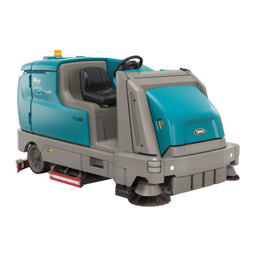
- Page 2 Always remember to recycle. INTENDED USE The M17 is an industrial rider machine designed to wet scrub and sweep both rough and smooth hard surfaces (concrete, tile, stone, synthetic, etc). Typical applications include schools, hospitals/health care facilities, offi ce buildings, and retail centers. Do not use this machine on soil, grass, artifi cial turf, or carpeted surfaces. This machine is intended for indoor use only.
-
Page 3: Table Of Contents
Replacing Or Rotating The Side Lithium-Ion Battery Pack ......59 Squeegee Blades ........90 Charging The Battery .......60 Replacing Or Rotating The Scrubbing To Charge With Tennant Branded Side Brush Squeegee Blades Charger ..........61 (Option) ..........91 To Charge With Enersys Battery Skirts And Seals ..........93 Charger ..........63... - Page 4 Cylindrical Brush Drive Belts ....95 Operation ..........158 Brakes ............95 Propel Controller Diagnostic Codes ....159 Tires ..............96 M17 Controller Custom Faults ....167 Pushing, Towing, And Transporting The Input Display Mode - Pro-Panel ....168 Machine ..........96 Input Display Mode - Standard Pushing Or Towing The Machine .....96 Control Panel ........170...
- Page 5 Sweep Vacuum Fan(s) Fail(s) To Actuator ..........312 Turn On ..........237 Testing The Main Scrub Brush Lift Hopper Lift Pump, Up ......238 Actuator ..........313 Hopper Fails To Lift ........239 Testing The Rear Squeegee Lift Hopper Lift Pump, Down ......240 Actuator ..........314 M17 9017358 (02-2020)
- Page 6 Adjusting The Rear Brake ......422 Spring Tube Assembly.......362 Debris Hopper ..........424 Removing/Reinstalling The Scrub Inspecting/Adjusting The Hopper Side Brush Motor (Option)....364 Snap Switch ........426 Removing/Installing The Solution Removing/Installing/Replacing The Tank Drain Hose ........368 Roll Out Actuator .......427 M17 9017358 (02-2020)
- Page 7 CONTENTS Programming/Adjusting The Roll Out Actuator ........430 Options ............436 Completely Opening Battery Compartment Cover (Machines Equipped With Optional Pressure Washer Or Live Wand) ......436 Servicing Lithium Ion Batteries ....438 Replacing The Battery Management System (BMS) ........438 M17 9017358 (02-2020)
-
Page 8: Important Safety Instructions - Save These Instructions
CAUTION: To warn of unsafe practices a Tennant representative for information on how to that could result in minor or moderate disable the cellular communication functionality. personal injury. - Page 9 - Do not modify the machine from its original - Follow site safety guidelines concerning wet design. fl oors. - Use Tennant supplied or approved - Do not leave machine unattended when replacement parts. fi lling solution tank with auto-fi ll feature.
- Page 10 SAFETY 6. When using Lithium-ion Battery Model: 7. When loading/unloading machine onto/off truck - Battery service to be performed by Tennant or trailer: Service only. - Use ramp, truck or trailer that will support the - Battery installation requires a specifi c weight of the machine and operator.
- Page 11 SAFETY M17 9017358 (02-2020)
- Page 12 / step in the lowered position. Do not carry passengers on any pat of the machine. Located on rear bumper door / step. FOR SAFETY LABEL - Authorized Service Mechanic Only. Located on circuit board cover and electrical panel. M17 9017358 (02-2020)
- Page 13 Located on both lift arms. Located on bottom of battery compartment cover. FOR SAFETY LABEL - Read manual before operating machine. WARNING LABEL - Raised hopper may fall. Engage hopper support bar. Located on hopper support bar. Located on electrical panel. M17 9017358 (02-2020)
- Page 14 Back injury could Severe personal injury can result from improper lifting. result. Wear eye protection. Use hoist when lifting. Hold sprayer with two hands. Located under high pressure washer cover. Located on high pressure washer cover. M17 9017358 (02-2020)
- Page 15 SAFETY Lithium- ion Battery Model: The safety label appears on the lithium- ion battery pack in the location indicated. Replace damaged labels. LITHUIM- ION BATTERY CAUTION LABEL - Located on top of battery pack. M17 9017358 (02-2020)
-
Page 16: General Information
X. Recovery tank drain hose K. Rear squeegee Y. Vacuum hose L. Overhead guard (Option) Z. Solution tank drain hose M. Steering wheel AA. High pressure washer (Option) N. Operator seat AB. Live wand dry vacuum (Option) M17 9017358 (02-2020) -
Page 17: Instruments And Controls
B. Directional switch L. Hopper rollout switch C. Emergency shut-off button D. Operating lights / hazard lights switch (Option) E. Spray nozzle switch (Option) / High pressure washer (Option) F. Parking brake pedal G. Brake pedal H. Propel pedal M17 9017358 (02-2020) -
Page 18: Standard Touch Panel
J. Main scrub brush pressure button W. Solution decrease button (−) K. Main scrub brush pressure indicator lights X. Solution fl ow indicator lights L. 1−STEP button Y. Solution increase button (+) Z. USB port (Service only) M17 9017358 (02-2020) -
Page 19: Pro-Panel Controls
J. Sweeping main brush button X. Hopper control button K. Sweeping vacuum fan button Y. USB port (Service only) L. Sweeping side brush button Z. Solution on / off buttons M. Rearview camera button N. Solution control access button M17 9017358 (02-2020) -
Page 20: Symbol Definitions
Hazard light Spray nozzle (Option) / Sweeping vacuum fan High Pressure washer (Option) Sweeping main brush Severe environment (Option) Scrubbing side brush Circuit breaker Scrubbing vacuum fan / squeegee Jack point Scrubbing main brush Forward / Reverse M17 9017358 (02-2020) - Page 21 Raise hopper Zone setting 2 Lower hopper Zone setting 3 Roll hopper out Battery discharge indicator Roll hopper in Hopper control access Alert / Fault Hour meter Checklist item uncon rmed Login Checklist item con rmed Logout Select M17 9017358 (02-2020)
- Page 22 Add / Edit pro les Enable login Operator Calibrate touch Supervisor Checklist setup Edit pro le Export all Add pro le Export new Delete pro le Export checklists Copy pro le Screen lock Enter Date / Time set M17 9017358 (02-2020)
- Page 23 GENERAL INFORMATION M17 9017358 (02-2020)
-
Page 24: Schematics
GENERAL INFORMATION SCHEMATICS ELECTRICAL SCHEMATIC (000000−010999) 356663 1075228 M17 9017358 (02-2020) - Page 25 GENERAL INFORMATION ELECTRICAL SCHEMATIC (000000−010999) - Page 2 356663 1075228 M17 9017358 (02-2020)
- Page 26 GENERAL INFORMATION ELECTRICAL SCHEMATIC (000000−010999) - Page 3 356663 1075228 M17 9017358 (02-2020)
- Page 27 GENERAL INFORMATION ELECTRICAL SCHEMATIC (000000−010999) - Page 4 356663 1075228 M17 9017358 (02-2020)
- Page 28 GENERAL INFORMATION ELECTRICAL SCHEMATIC (000000−010999) - Page 5 356663 1075228 M17 9017358 (02-2020)
- Page 29 GENERAL INFORMATION ELECTRICAL SCHEMATIC (000000−010999) - Page 6 356663 1075228 M17 9017358 (02-2020)
-
Page 30: Electrical Schematic (011000−011999)
GENERAL INFORMATION ELECTRICAL SCHEMATIC (011000−011999) - Page 1 356663 1075228 M17 9017358 (02-2020) - Page 31 GENERAL INFORMATION ELECTRICAL SCHEMATIC (011000−011999) - Page 2 356663 1075228 Page 1 M17 9017358 (02-2020)
- Page 32 GENERAL INFORMATION ELECTRICAL SCHEMATIC (011000−011999) - Page 3 356663 1075228 M17 9017358 (02-2020)
- Page 33 GENERAL INFORMATION ELECTRICAL SCHEMATIC (011000−011999) - Page 4 Page 2 356663 1075228 M17 9017358 (02-2020)
- Page 34 GENERAL INFORMATION ELECTRICAL SCHEMATIC (011000−011999) - Page 5 356663 1075228 M17 9017358 (02-2020)
- Page 35 GENERAL INFORMATION ELECTRICAL SCHEMATIC (011000−011999) - Page 6 356663 1075228 M17 9017358 (02-2020)
- Page 36 GENERAL INFORMATION ELECTRICAL SCHEMATIC (011000−011999) - Page 7 356663 1075228 M17 9017358 (02-2020)
-
Page 37: Electrical Schematic (012000− )
GENERAL INFORMATION ELECTRICAL SCHEMATIC (012000− Page 1 356663 1075228 M17 9017358 (02-2020) - Page 38 GENERAL INFORMATION ELECTRICAL SCHEMATIC (012000− Page 2 356663 1075228 M17 9017358 (02-2020)
- Page 39 GENERAL INFORMATION ELECTRICAL SCHEMATIC (012000− Page 3 356663 1075228 M17 9017358 (02-2020)
- Page 40 GENERAL INFORMATION ELECTRICAL SCHEMATIC (012000− Page 4 356663 1075228 M17 9017358 (02-2020)
- Page 41 GENERAL INFORMATION ELECTRICAL SCHEMATIC (012000− Page 5 356663 1075228 M17 9017358 (02-2020)
- Page 42 GENERAL INFORMATION ELECTRICAL SCHEMATIC (012000− Page 6 356663 1075228 M17 9017358 (02-2020)
- Page 43 GENERAL INFORMATION ELECTRICAL SCHEMATIC (012000− Page 7 356663 1075228 M17 9017358 (02-2020)
-
Page 44: Electrical Schematic Symbols
3 Phase AC Induction Motor Energized Relay Coil Adaptor Harness Motor Encoder N.C. Relay Contacts Sensor (Variable Resistor) Notes Momenary Switch N.O. N.O. Relay Contacts Assembly Contact Switch N.C. Horn or Alarm AC Plug Solenoid Valve Capacitor Light M17 9017358 (02-2020) -
Page 45: Fastener Torques
424 - 550 Nm 508 - 660 Nm 177 - 230 Nm 409 - 530 Nm 574 - 745 Nm 686 - 890 Nm 227 - 295 Nm 520 - 675 Nm 732 - 950 Nm 879 - 1140 Nm M17 9017358 (02-2020) -
Page 46: Specifi Cations
M17 9017358 (02-2020) - Page 47 Maximum ramp incline for transporting (GVWR) (Direct throw option with hopper raised) Maximum ramp incline for transporting (GVWR) (Direct throw option with hopper lowered) ° 3 ° 0 Minimum temperature for operating machine scrubbing functions 0° C (32° F) M17 9017358 (02-2020)
- Page 48 Rear (2) Solid 125 mm wide x 380 mm OD (5 in wide x 15 in OD) SCRUBBING SIDE BRUSH SOLUTION FLOW RATE (OPTION) Item Measure Solution pump 36 Volt DC up to 1.51 LPM (0.40 GPM) M17 9017358 (02-2020)
- Page 49 1700 mm (67 in) 2096 mm (82.5 in) 1480 mm (58.25 in) Track Wheel base (at rear wheels) 1163 mm 1041 mm (46 in) (41 in) (S/N 000000-010999) 2850 mm (112.1 in) (S/N 011000- 2865 mm (112.8 in) M17 9017358 (02-2020)
-
Page 50: Maintenance
MAINTENANCE MAINTENANCE M17 9017358 (02-2020) - Page 51 Rotate brushes from front to (cylindrical) rear Rotate end for end Main sweeping brushes Rotate brushes from front to Dual Force (cylindrical) rear Rotate end for end Main sweeping brush Rotate end for end Direct Throw (cylindrical) M17 9017358 (02-2020)
- Page 52 Hopper chains Lubricate and check for dam- age and wear. Hopper lift arm pivots Lubricate Scrub vacuum fan Check motor brushes 1 (2) Hours motor(s) Tires Check for damage and wear Hopper chains ■ Check tension. M17 9017358 (02-2020)
- Page 53 Distilled water. Special lubricant, Lubriplate EMB grease (Tennant part number 01433-1) SAE 90 weight gear lubricant HYDO Tennant True premium hydraulic fl uid or equivalent NOTE: More frequent maintenance intervals may be required in extremely dusty conditions. M17 9017358 (02-2020)
-
Page 54: Yellow Touch Points
200 hours. DRIVE WHEEL OIL The drive wheel oil plug is located near the bottom of the drive wheel assembly. Change the drive wheel oil after every 800 hours. M17 9017358 (02-2020) -
Page 55: Hopper Lift Arm Pivots
HIGH PRESSURE WASHER OIL Change the high pressure washer oil after the initial 50 hours of high pressure washer operation. NOTE: Remove high pressure washer cover to access both the high pressure washer drain plug and vented fi ll cap. M17 9017358 (02-2020) -
Page 56: Hopper Chains
500 hours after that. With the hopper in the lowered position; the longer arm chain (A) should not move more than 25 mm (1 in) and the shorter lintel chain (B) should not move more than 12 mm (0.5 in). M17 9017358 (02-2020) -
Page 57: Hydraulics
VI 163 or higher 1057708 19 L (5 gal) If using a locally-available hydraulic fl uid, be sure the specifi cations match Tennant hydraulic fl uid specifi cations. Substitute fl uids can cause premature failure of hydraulic components. ATTENTION! Hydraulic components depend on system hydraulic fl... -
Page 58: Battery
– Allow the charger to completely charge the battery before re using the machine. NOTE: Make sure the battery caps are in place while charging. There may be a sulfur smell after charging batteries. This is normal. M17 9017358 (02-2020) -
Page 59: Maintenance-Free Batteries
When removing or replacing the lithium ion battery pack, use non-conductive lifting straps positioned at all four lift points with straps angled at 45° or greater when hoisting battery pack. • Contact Tennant Service for lithium-ion battery service and replacement. M17 9017358 (02-2020) -
Page 60: Charging The Battery
4. Plug the charger AC power supply cord into a properly grounded outlet. 5. Disconnect the battery side cable connector from the machine by pulling down on the connector or the battery quick-disconnect lever (option). Do not pull on the cables. M17 9017358 (02-2020) -
Page 61: To Charge With Tennant Branded Charger
MAINTENANCE TO CHARGE WITH TENNANT BRANDED 2. Observe the charger display. CHARGE CHARGER appears on the display when the battery is charging. This is the charger default screen. 1. Turn on the battery charger if required. Charger Display: WARNING: Batteries emit hydrogen gas. - Page 62 COMPLETE will appear in the display, all the charger status indicators will be illuminated, and the Tennant charger will stop charging when the battery is completely charged. FOR SAFETY: When servicing machine do not disconnect the off-board charger’s DC...
-
Page 63: To Charge With Enersys Battery Charger
The charger will return to the default screen. Refer to manufacture’s operator manual for additional information. 2. Observer the charger display. The charging indicator will illuminate on the display when the battery is charging. This is the charger default screen. M17 9017358 (02-2020) - Page 64 USB port. Do Not plug anything into the USB port while the battery is charging. 5. After the batteries have completely charged, disconnect the charger connector from the battery cable connector. M17 9017358 (02-2020)
-
Page 65: Opportunity Charging (Option)
See CHECKING THE ELECTROLYTE LEVEL. 4. Disconnect the battery side cable connector from the machine by pulling down on the 6. The battery will be opportunity charged during connector. Do not pull on the cables. the break. M17 9017358 (02-2020) -
Page 66: Weekly Equalization Charge
The default day can be changed to another FOR SAFETY: When servicing machine do not day if necessary. Consult a Tennant service disconnect the off-board charger’s DC cord representative about changing the default day. - Page 67 MAINTENANCE The yellow charging indicator will go out and the green charge complete indicator will be illuminated when the battery equalization charge is complete. M17 9017358 (02-2020)
-
Page 68: Battery Watering System (Option)
NOTE: The water supply to the battery water system must always be 7.57 LPM (2 GPM) or more. Use the purger to confi rm the water supply pressure. Refer to manufacturer Operator Manual for additional information. M17 9017358 (02-2020) -
Page 69: Fuel Cell Battery (Option)
MAINTENANCE FUEL CELL BATTERY (OPTION) Machines can be equipped for use with fuel cell battery systems. Contact the fuel cell battery provider for all fuel cell battery information. M17 9017358 (02-2020) -
Page 70: Circuit Breakers, Fuses, And Relays
2.5A Strobe light/Flashing light on hopper compartment. recovery tank (Option) CB15 Power steering CB16 Lift module CB17 Sweep module CB18 Sweep vacuum fan 1 CB19 Sweep vacuum fan 2 CB20 Not used CB21 2.5A Alarm/Flashing light (Option) M17 9017358 (02-2020) -
Page 71: Fuses
Refer to the table below for the relays and circuits controlled. Relay Rating Circuit Controlled 36 VDC, 200 A Main contactor 36 VDC, 5 A Backup alarm / light (Option) 36 VDC, 100 A Auxiliary line contactor 36 VDC, 200A Sweep contactor M17 9017358 (02-2020) -
Page 72: Hopper Dust Filter/Perma-Filter
1. Remove the hopper cover from the hopper. 5. Clean dust and debris from the dust fi lter tray. 2. Remove the dust fi lter cover. 6. Reinstall the dust fi lter. 7. Reinstall the dust fi lter cover. 8. Reinstall the hopper cover. M17 9017358 (02-2020) -
Page 73: Cleaning The Hopper Dust Filter
If there is a fi re in the hopper, the Thermo-Sentry stops the vacuum fan and cuts off the air fl ow. The Thermo-Sentry automatically resets after cooling down. M17 9017358 (02-2020) -
Page 74: Main Scrub Brushes
REPLACING DISK SCRUB BRUSHES OR PAD DRIVERS 1. Raise the scrub head. 2. Turn off the machine. FOR SAFETY: Before leaving or servicing machine, stop on level surface, turn off machine, set parking brake, and remove key. M17 9017358 (02-2020) -
Page 75: Replacing Disk Scrub Pads
9. Close and secure the squeegee support door driver. and close the main brush access door. 5. Reinstall the pad driver onto the machine. 10. Repeat procedure for the other brushes. M17 9017358 (02-2020) -
Page 76: Cylindrical Scrub Brushes
2. Lift the idler plate retainer handle and unhook 6. If rotating the brushes, always rotate the front the retainer ring from the idler plate hook. with the back so that they wear evenly. They may be rotated end for end as well. Before After M17 9017358 (02-2020) - Page 77 9. Close and secure the squeegee support door and close the main brush access door. 10. Repeat for the brush on the other side of the scrub head. M17 9017358 (02-2020)
-
Page 78: Main Sweep Brushes
6. Slide the brushes into the main sweep brush compartment and all the way onto the drive hubs. 7. Reinstall the main sweep brushes idler plate. 8. Close the main sweeping brush compartment access door. M17 9017358 (02-2020) -
Page 79: Replacing The Direct Throw Main Sweeping Brush (Option)
8. Slide the brush into the main sweep brush compartment and completely onto the drive hub. 9. Reinstall the main sweep brush idler plate. 10. Reinstall the idler side skirt and plate. 11. Close the main sweeping brush compartment access door. 12. Lower the hopper. M17 9017358 (02-2020) -
Page 80: Side Brush(Es)
fl oor between 9 o’clock and 2 o’clock when the brushes are in motion. 3. Remove the side brush and retainer from under the side brush assembly. 350327 M17 9017358 (02-2020) -
Page 81: To Adjust Sweeping Side Brush - Standard Panel
The selected side brush will lower and spin. NOTE: Contact a Tennant service representative if there is a fl at pattern (full circle) after the sweeping side brushes have been adjusted. 4. Observe the brush pattern... -
Page 82: To Adjust Sweeping Side Brush - Pro-Panel
9. Recheck the brush patterns. Adjust brush pressure as necessary. NOTE: Contact a Tennant service representative if 4. Press the desired sweeping side brush button there is a fl at pattern (full circle) after the sweeping to adjust it. -
Page 83: Replacing The Scrubbing Side Brush (Option)
6. Place the new side brush underneath the side brush assembly and lift the side brush up onto the side brush hub until the brush locks onto the hub. 7. Reinstall the scrubbing side brush squeegee assembly. M17 9017358 (02-2020) -
Page 84: Squeegee Blades
FOR SAFETY: Before leaving or servicing machine, stop on level surface, turn off machine, set parking brake, and remove key. 2. Disconnect the vacuum hose from the rear squeegee assembly 4. Pull the rear squeegee assembly from the machine. M17 9017358 (02-2020) - Page 85 8. Insert the hinge end of the retainer into the hooks in the rear squeegee assembly. 6. Remove the rear squeegee from the squeegee assembly. M17 9017358 (02-2020)
- Page 86 12. Remove the front squeegee from the squeegee assembly. 10. Turn the rear squeegee assembly over to access the front of the squeegee assembly. M17 9017358 (02-2020)
- Page 87 14. Install the front squeegee retainer onto the rear squeegee assembly. 15. Reinstall the rear squeegee assembly onto the machine 16. Raise the rear bumper door / step if it was lowered to access the rear squeegee assembly. M17 9017358 (02-2020)
-
Page 88: Leveling The Rear Squeegee
5. To adjust the squeegee leveling, loosen the tilt if adjustments were made. lock knob. 9. Readjust the squeegee blade defl ection if necessary. 10. Raise the Rear bumper door / step when fi nished leveling the rear squeegee. M17 9017358 (02-2020) -
Page 89: Adjusting The Rear Squeegee Blade Deflection
8. Readjust the squeegee blade defl ection if 3. Lower the rear bumper door / step. necessary. 9. Raise the rear bumper door / step when fi nished adjusting the rear squeegee blade defl ection. M17 9017358 (02-2020) -
Page 90: Replacing Or Rotating The Side Squeegee Blades
4. Remove the retaining band from the side squeegee assembly. 9. Close and secure the squeegee support door and close the main brush access door. 10. Repeat for the side squeegee on the other side of the scrub head. M17 9017358 (02-2020) -
Page 91: Replacing Or Rotating The Scrubbing Side Brush Squeegee Blades (Option)
NOTE: The squeegee blade(s) have slots for adjusting the squeegee blade defl ection. Install / reinstall squeegees so the defl ection is approximately 12 mm (0.50 in) for smooth fl oors and 15 mm (0.62 in) for rough fl oors. M17 9017358 (02-2020) - Page 92 5. Fasten the side brush retaining band latch. spacer, and retaining band onto the side brush assembly. Be sure the holes in the squeegee blade are hooked onto the tabs. 6. Reinstall the side brush squeegee assembly onto the side brush assembly. M17 9017358 (02-2020)
-
Page 93: Skirts And Seals
The side skirts are located on both sides of the main sweeping brushes. The side skirts should be just touching the fl oor. Check the skirts after every 50 hours of operation for damage and wear. Dual Force Sweeping Skirts Direct Throw Sweeping Skirts (Option) M17 9017358 (02-2020) -
Page 94: Scrub Head Skirts (Disk Scrub Heads Only)
Check the hopper dust fi lter cover seal for wear or LIVE WAND VACUUM SEALS (OPTION) damage every 100 hours of operation. Clean dust and debris from the seal as necessary. Check the live wand vacuum seals for damage and wear after every 50 hours of operation. M17 9017358 (02-2020) -
Page 95: Belts
The foot pedal should not travel more than 25 mm (1 in) to engage the brake. Check the brake adjustment after every 200 hours of operation. Direct Throw Sweeping Drive Belt (Option) M17 9017358 (02-2020) -
Page 96: Tires
TRANSPORTING THE MACHINE TIRES FOR SAFETY: When transporting Lithium- ion FOR SAFETY: Before leaving or servicing Battery Model, contact Tennant or your local machine, stop on level surface, turn off regulatory authorities for proper transporting machine, set parking brake, and remove key. - Page 97 7. Lower the hopper, scrub head, and rear squeegee. 8. Connect the tie-down straps to the holes in the rear jacking brackets at the front of the machine. 9. Turn off machine and remove the key. M17 9017358 (02-2020)
-
Page 98: Machine Jacking
FOR SAFETY: When servicing machine, block machine tires before jacking machine up. Use a hoist or jack that will support the weight of the machine. Jack machine up at designated locations only. Support machine with jack stands. M17 9017358 (02-2020) -
Page 99: Ec-H2O Module Flush Procedure
6. Pour 2 gallons (7.6 liters) of white or rice hose. vinegar into the solution tank. 3. Remove the drain hose from the ec-H2O compartment. M17 9017358 (02-2020) - Page 100 11. Disconnect the drain hose from the ec-H2O manifold hose. 12. Reconnect the outlet hose to the ec-H2O manifold hose. 13. Return the drain hose to storage location in the ec-H2O compartment. 14. Close the right shroud. M17 9017358 (02-2020)
-
Page 101: Storage Information
(+) until the solution fl ow is at the highest setting. 1. Completely drain the solution tank, recovery tank, and detergent tank. 2. Pour 7.6 L (2 gal) of Propylene Glycol Based/ Recreational Vehicle (RV) antifreeze into the solution tank. Standard Panel Pro-Panel M17 9017358 (02-2020) - Page 102 16. The remaining antifreeze does not need to be drained from the solution tank, recovery tank, 8. Machines with scrubbing side brush option or detergent tank. only: Press the scrubbing side brush button to activate the side brush. Standard Panel Pro-Panel M17 9017358 (02-2020)
-
Page 103: Preparing The Machine For Operation After Storage
4. Machines equipped with optional detergent machine is ready for operation. See PRIMING tank only: Pour 1.9 L (1/2 gal) of cool clean THE ec-H2O SYSTEM for additional instructions. water into the detergent tank. 5. Turn on the machine. M17 9017358 (02-2020) - Page 104 NOTE: Machines equipped with optional ES system will need to drain the antifreeze from the pump lines. 12. Stop the machine. 13. Machines with spray nozzle option only: Operate the wand for a few seconds to clean the antifreeze from the pump. M17 9017358 (02-2020)
-
Page 105: Priming The Ec-H2O System
5. Connect the drain hose to the ec-H2O outlet hose. 2. Open the right shroud to access the ec-H2O assembly. 3. Press the connector button to disconnect the outlet hose from the ec-H2O manifold. 6. Place the drain hose into a empty container. M17 9017358 (02-2020) - Page 106 10. Disconnect the drain hose from the ec-H2O manifold hose. 11. Reconnect the outlet hose to the ec-H2O manifold hose. 12. Place the drain hose back into the ec-H2O compartment. 13. Close the right shroud. M17 9017358 (02-2020)
-
Page 107: Supervisor Controls
If the new assigned supervisor mode login number is forgotten, please contact Tennant service. Press the backspace button if necessary to delete and reenter a number. -
Page 108: Entering The Supervisor Mode
Press the backspace button if necessary to delete and reenter a number. 3. The supervisor machine operation screen should appear in the display. Press the settings button to access the supervisor settings screen. M17 9017358 (02-2020) -
Page 109: Supervisor Setting Screen/Screen Icons
Screen Lock setting Screen. See SETTING THE SCREEN LOCK. Press the home button to navigate back to the main operating screen. Press the back button to navigate back to the previous screen. M17 9017358 (02-2020) -
Page 110: Adding/Editing Profiles
Press the Delete Profi le button to delete an existing profi le. Press the home button to navigate back to the main operating screen. Press the back button to navigate back to the previous screen. M17 9017358 (02-2020) - Page 111 Press the mph button to set the machine speed to miles per hour. Press the km/h button to set the machine speed to kilometers per hour. Press the enter button to set the maximum speed for the machine. M17 9017358 (02-2020)
-
Page 112: Enabling The Login
Turning the key to the off position is another way to also logout. 13. Use the Edit Profi le button, Copy Profi le button, and Delete Profi le button to manage the current user profi les. M17 9017358 (02-2020) -
Page 113: Disabling The Login
3. Press the yes button to enter the Default User screen. 4. Press either the Operator button or Supervisor button to select the desired default user. M17 9017358 (02-2020) -
Page 114: Changing Battery Type
1. Turn on the machine, login to the main operation screen, and press the setting button to access the supervisor settings screen. See ENTERING THE SUPERVISOR MODE. 2. Press the Calibrate Touch button to recalibrate touch. If the touch points become misaligned. M17 9017358 (02-2020) -
Page 115: Exporting Checklists
Press the home button to navigate back to the export screen. the main operating screen. Press the back button to navigate back to the previous screen. 5. Remove the fl ash drive from USB port and turn off the machine. M17 9017358 (02-2020) -
Page 116: Checklist Setup
Press the home button to navigate back to the main operating screen. Press the down arrow button to scroll down through Pre-Operation Checklist items. Press the back button to navigate back to the previous screen. M17 9017358 (02-2020) -
Page 117: Disabling/Enabling The Pre-Operation
ENTERING THE SUPERVISOR MODE. 2. Press the Checklist Setup button to access the Pre-Operation Checklist setup screen. Press the home button to navigate back to the main operating screen. Press the back button to navigate back to the previous screen. M17 9017358 (02-2020) -
Page 118: Changing The Rear View Camera Settings
Press the home button to navigate back to the main operating screen. Press the back button to navigate back to the previous screen. M17 9017358 (02-2020) - Page 119 Press the backspace button if necessary to delete and reenter a number. Press the space button to place space between letters / numbers. Press the pound button to toggle between the number keypad and the letter keypad. M17 9017358 (02-2020)
-
Page 120: Setting/Changing The Date And Time
Press the back button to navigate back to the previous screen. 3. Press the home button when fi nished setting / changing the system date and time to return to the main operating screen. M17 9017358 (02-2020) -
Page 121: Setting/Changing The Screen Lock
Press the up arrow button to scroll up through screen lock times. 3. Press the home button when fi nished setting / changing the screen lock time to return to the main operating screen. M17 9017358 (02-2020) -
Page 122: Troubleshooting
Solution Tank Empty Main Scrub/Solution Delivery Module, Right Motor J4-1 ≈ < 0.73 VDC J11-4, J11-5, J11-6, J9-6, Low Battery Voltage Propel Controller, J9-7, J9-8, J9-9, J1-1 ≈ < 32 VDC J9-10 Circuit Fault CAN to Interface Module M17 9017358 (02-2020) - Page 123 Propel Controller, Left Motor Command J1-16 ≈ 0.2-5 State J1-16 ≈ 0 VDC J3-2 CB-17, J4-17 Low Battery Voltage Propel Controller, J1-1 ≈ < 32 VDC Right Motor Circuit Fault CAN to Interface J3-2 CB-17, Module J4-16 M17 9017358 (02-2020)
- Page 124 Module Side Sweep Side Sweep/ 1-Step ON Interface Module, 1-Step OFF Interface Module, Brushes Down Vacuum Module: Side Sweep Selected Interface Module, Side Sweep Interface Module, Deselected Left Side Actuator J4-11, J4-12 Right Side Actuator J4-1, J4-2 M17 9017358 (02-2020)
- Page 125 1/2 full and Solution Delivery Delivery Module, solution tank is Module, J4-1 ≈ > 1.34 VDC not full. J4-1 ≈ < 1.34 Low Battery Voltage Propel Controller, J1-1 ≈ < 32 VDC Circuit Fault CAN to Interface Module M17 9017358 (02-2020)
- Page 126 Deselected Rear Forward/Reverse Propel Controller, Neutral - Ready Propel Controller, J7-1, J7-3 Command J1-16 ≈ 0.2-5 State J1-16 ≈ 0 VDC Low Battery Voltage Propel Controller, J1-1 ≈ < 32 VDC Circuit Fault CAN to Interface Module M17 9017358 (02-2020)
- Page 127 Main Sweep/ Filter Shaker Button Filter Shaker Button Hopper Lift Module Main Sweep 1-Step ON Deselected J4-15, J4-11, Dust Vacuum Sweep Function CB-17 Deselected Enabled 1-Step OFF Hopper Not Home Main Sweep/Hopper Lift Module: J4-4 = Not Grounded M17 9017358 (02-2020)
- Page 128 Washer Switch ON Washer Switch OFF High Pressure Wire Harness J6-16, CB-10 Dry Vacuum Main Scrub/ Dry Vacuum Switch Dry Vacuum Switch System (Option) Solution Delivery Module: Dry Vacuum Wire Harness J4-1, J4-2, J4-3, J4-4, J4-5, J4-6 M17 9017358 (02-2020)
-
Page 129: Faults And Warnings
A fault / alert screen will appear in the display. Fault/alert text will appear under the icon in the center of the screen. The LCD will display a fault code. If there is more than one fault, each fault code will alternately display.\ M17 9017358 (02-2020) -
Page 130: Fault Codes Table
2. Check circuit breaker supplying power to 2. Side Sweep/Vacuum Module lost Side Sweep/Vacuum Module. power (wiring issue). 3. No communication with Side Sweep/ 3. Circuit breaker supplying power to Vacuum Module. Side Sweep/Vacuum Module tripped. 4. Side Sweep/Vacuum Module may be damaged. M17 9017358 (02-2020) - Page 131 1. Wiring, connector, or Main Sweep/ 1. Check connections, Main Sweep/Hopper Motor 1 Open Hopper Lift Module issue with circuit Lift Module gets power from key switch and Warning to motor. battery. If connections are good, replace Main Sweep/Hopper Lift Module. M17 9017358 (02-2020)
- Page 132 2. Replace Main Sweep/Hopper Lift 2. Power/battery issue on startup. Module. 0x0247 RSwpAct FET Right Sweep 1. Side Sweep/Vacuum Module 1. Check voltage references. Actuator FET Fault problem. 2. Replace Side Sweep/Vacuum Module. 2. Power/battery issue on startup. M17 9017358 (02-2020)
- Page 133 1. Check wire harness. Repair as needed. 2. Higher current draw than hardware design limit. 0x0327 Alarm FET Alarm FET Fault 1. Propel Controller problem. 1. Check voltage references. 2. Power/battery issue on startup. 2. Replace Propel Controller. M17 9017358 (02-2020)
- Page 134 1. Current draw higher than expected. 1. Verify vacuum load, damage and/or Current 1 Fault usage conditions. 0x0515 Vac 2 OC2 Pickup Vac 2 Over 1. Current draw higher than expected. 1. Verify vacuum load, damage and/or Current 2 Fault usage conditions. M17 9017358 (02-2020)
- Page 135 4. ec-H2O Module may be damaged. 0x0711 Ec Pump Opn EC-H2O Pump Open 1. Wiring, connector, or ec-H2O 1. ec-H2O Module is not detecting pump Fault Module issue with circuit to motor. current. Check connections for voltage and verify pump is operating. M17 9017358 (02-2020)
- Page 136 2. Clean fi lter. 0x07A1 Hopper Fire Hopper on Fire 1. Hopper on fi re. 1. Extinguish hopper fi re. 0x07A2 Hopper not in Home 1. Hopper not completely lowered. 1. Completely lower hopper. position 2. Check actuator for binding. M17 9017358 (02-2020)
- Page 137 CLEAR: Power cycle machine. 0x2000 Pascal Flt Touchscreen Error 1. Touchscreen control board 1. Replace pod. problem. A Service Diagnostics tool is available to provide additional fault detail. See SERVICE DIAGNOSTICS TOOL in SERVICE section. M17 9017358 (02-2020)
-
Page 138: Lithium Ion Battery Indicator Codes
Cell Modules and fully tightened. If problem persists, measure raw battery voltage between B+ and B-. If voltage is greater than 30V, replace BMS. If voltage is less than 30V, replace Battery Pack. M17 9017358 (02-2020) - Page 139 BMS Cell Under Voltage Stop use of machine and CELL_UNDERVOLT_ modules has too high a Protection 1 recharge battery. If fault repeats, PROTECTION_1 voltage (above 3.0 volts contact service. per cell). Will cause BMS to turn off. M17 9017358 (02-2020)
- Page 140 CAN_LOST (UI) and BMS has been to BMS. Verify no other interrupted. connectors of Tap Harness have been disconnected. If problem persists, contact service for possible replacement of BMS or other components on CAN bus. M17 9017358 (02-2020)
- Page 141 0x0D33 FAULT_LPBMS_BUS_ BMS temperature has BMS Bus-Bar Temp Warning Stop using or charging machine. BAR_TEMP_WARN exceeded specifi cation. Allow battery to cool down, Machine will stop operation. before restarting operation. If fault repeats, contact service. M17 9017358 (02-2020)
- Page 142 Over temperature condition BMS Over Temp Discharge Stop operating machine. Allow THRESH_ detected during a cleaning Threshold Warning battery to cool down, before OVERTEMP_ operation. Machine will stop restarting operation. If fault DISCHARGE_WARN operation. repeats, contact service. M17 9017358 (02-2020)
- Page 143 TROUBLESHOOTING M17 9017358 (02-2020)
-
Page 144: Service Modes
All self-test mode settings will appear on the screen as the particular system is being tested. See the table on the following page for a list of self-tests. NOTE: Machines functions are briefl y automatically activated while each function is being tested. M17 9017358 (02-2020) - Page 145 Test Propel CAN Communication... S36:L Side Swp Act J4-11,12 S73:Side Sweep S37:R Side Swp Act J4-1,2 S74:Propel Ctrl NOTE: LCD messages above can be seen as an open or a short. 11. Turn key switch OFF after self-test is completed. M17 9017358 (02-2020)
-
Page 146: Self-Test Mode - Standard Control Panel
5. Press and release the brush pressure button to activate the self-test. SELF-TEST STARTING will appear on the LCD. ****SELF-TEST*** STARTING 3. Release the confi guration mode button when CONFIG MODE appears on the LCD. STP002 CONFIG MODE M17 9017358 (02-2020) - Page 147 S35:L Side Swp Act J4-11,12 S72:Main Sweep Test Propel CAN Communication... S36:L Side Swp Act J4-11,12 S73:Side Sweep S37:R Side Swp Act J4-1,2 S74:Propel Ctrl NOTE: LCD messages above can be seen as an open or a short. M17 9017358 (02-2020)
-
Page 148: Configuration Mode - Pro-Panel
CONFIG MODE. The fi rst confi guration mode item will appear. 4. Use the keypad to enter the Service login number (083957530) into the display above the keypad. CONFIG MODE Touch the enter button when fi nished entering the Service login number. M17 9017358 (02-2020) - Page 149 fi guration, down pressure targets, fl ow range, side option, travel speeds, autofi ll option, SE option to default settings. C20:Battery Type Confi gure battery type. C21:Dust Vac Confi gure dust vacuums C22:Side Sweep Confi gure side sweep motors M17 9017358 (02-2020)
- Page 150 OFF. Return to the Confi guration Mode menu to make additional changes. If machine is turned off it will be necessary to log back into the main service menu and return to the Confi guration Mode to make additional changes. M17 9017358 (02-2020)
-
Page 151: Configuration Mode - Standard Control Panel
See the table on the next page for a list of utilities. C5 SE/None 3. Release the confi guration mode button when 0-1-2-3% Mix Ratio CONFIG MODE appears on the LCD. STP002 CONFIG MODE M17 9017358 (02-2020) - Page 152 “No” changes to “Yes” following Step 7. This completes the reset process. ** C12, C13, and C14 Main Press (Main Brush Pressure) adjustments set the maximum brush motor amp draw for each down pressure setting; 1 LED, 2 LEDs, or 3 LEDs. M17 9017358 (02-2020)
-
Page 153: Propel Diagnostic Mode - Pro-Panel
PROPEL DIAG MODE appears. 4. Use the keypad to enter the Service login number PROPEL DIAG MODE (083957530) into the display above the keypad. Touch the enter button when fi nished entering the Service login number. M17 9017358 (02-2020) - Page 154 TROUBLESHOOTING 8. Touch and release the left arrow button or right arrow button until the desired M17 Propel Diagnostic Mode appears. See table below for how each input operates. P1:Curtis Online P6:Motor Current XXXX.X A P7:Motor Temp XXX.X C 9. To exit PROPEL DIAG MODE, either turn key switch OFF, or exit PROPEL DIAG MODE and return to the Service Modes menu.
- Page 155 TROUBLESHOOTING M17 9017358 (02-2020)
-
Page 156: Propel Diagnostic Mode - Standard Control Panel
5. Press and release the brush pressure button to enter Propel Diagnostic Mode. P1:Curtis Online... will appear on the LCD. P1: Curtis Online/ Error 3. Release the confi guration mode button when CONFIG MODE appears on the LCD. STP002 CONFIG MODE M17 9017358 (02-2020) - Page 157 6. Press and release the confi guration mode button to scroll through a list of Curtis 1234 controller inputs. See the table below for a list of utilities P1: Curtis Online/ Error P6:Motor Current XXXX.X A P7:Motor Temp XXX.X C M17 9017358 (02-2020)
-
Page 158: Propel Controller Diagnostic Led Operation
LED flashes the appropriate number of times for the second digit. Example: Battery Undervoltage (Code 23) YELLOW YELLOW (first digit) (second digit) Curtis Controller Diagnostics LED Operation and Curtis Diagnostic Codes taken from the Curtis 1234/36/38 Manual. © Curtis Instruments, Inc. (PN: 37022 Date: 01 March 2011) M17 9017358 (02-2020) -
Page 159: Propel Controller Diagnostic Codes
4. Battery disconnected while driving. Severe Undervoltage limit. 5. See Monitor menu » Battery Capacitor Voltage. 6. Blown B+ fuse or main contactor did not close. Terms: KSI = Key Switch Interlock FET = Field Effect Translator M17 9017358 (02-2020) - Page 160 Output 6 driver (pin 19) is too low. Clear: BRemedy the overcurrent cause will not turn on. and use the VCL function Set_DigOut() to turn the driver on again. Terms: KSI = Key Switch Interlock FET = Field Effect Translator M17 9017358 (02-2020)
- Page 161 Set: Driver 4 (pin 3) is either open or 2. Dirty connector pins. ShutdownDriver4. shorted. 3. Bad crimps or faulty wiring. Clear: Correct open or short, and cycle driver. Terms: KSI = Key Switch Interlock FET = Field Effect Translator VCL = Vehicle Control Language M17 9017358 (02-2020)
- Page 162 2. Pot2 wiper voltage too high. changed with the VCL function Setup_Pot_Faults()). Clear: Bring Pot2 wiper voltage below the fault threshold. Terms: KSI = Key Switch Interlock FET = Field Effect Translator VCL = Vehicle Control Language M17 9017358 (02-2020)
- Page 163 Set: See OEM documentation. (See OEM documentation.) OEM and are implemented in the Clear: See OEM documentation. application-specific VCL code. See OEM documentation. Terms: KSI = Key Switch Interlock FET = Field Effect Translator VCL = Vehicle Control Language M17 9017358 (02-2020)
- Page 164 Fault On Other Traction manual. Controller Dual Severe Fault Dual Drive fault: see Dual Drive manual. Terms: KSI = Key Switch Interlock FET = Field Effect Translator VCL = Vehicle Control Language CAN = Controller Area Network M17 9017358 (02-2020)
- Page 165 Stall Fault, clear by 4. Vehicle is stalled. ensuring encoder senses proper operation, Motor RPM = 0, and Throttle Command = 0. Terms: KSI = Key Switch Interlock FET = Field Effect Translator VCL = Vehicle Control Language M17 9017358 (02-2020)
- Page 166 2. Software and hardware do not match. your controller model. ShutdownPump. 3. Controller defective. Dualmotor Parameter Mismatch Dual Drive fault: see Dual Drive manual. Terms: KSI = Key Switch Interlock FET = Field Effect Translator EMR = Emergency Reverse M17 9017358 (02-2020)
-
Page 167: M17 Controller Custom Faults
TROUBLESHOOTING M17 CONTROLLER CUSTOM FAULTS Code Condition Cause of Condition Clear Condition Action Throttle SRO Fault Throttle is active at same time service Release throttle to Shutdown Throttle brake is pressed. neutral HPD Fault 1.Throttle is active immediately after Release throttle to Shutdown Throttle timer set by “Throttle PowerUp Check... -
Page 168: Input Display Mode - Pro-Panel
INPUT DISPLAY appears. 4. Use the keypad to enter the Service login number (083957530) into the display above the keypad. INPUT DISPLAY Touch the enter button when fi nished entering the Service login number. M17 9017358 (02-2020) - Page 169 9. Touch any other button to display a corresponding text message. The message confi rms the control module received the input. 10. To exit Input Display Mode, either turn key switch OFF, or exit Input Display Mode and return to the main Service Modes menu. M17 9017358 (02-2020)
-
Page 170: Input Display Mode - Standard Control Panel
5. Press and release the brush pressure button to enter Input Display Mode. I1:Solution Tank Level:X XV will appear on the LCD. I1:Solution Tank Level: X 3. Release the confi guration mode button when CONFIG MODE appears on the LCD. STP002 CONFIG MODE M17 9017358 (02-2020) - Page 171 (clogged filter input) I4:Seat Switch: I9:Flush Button Seated I10:SE Switch I5:Shaker Switch: Off/On Off/On 7. Press any other touch panel button to display a corresponding LCD text message. The message confi rms that the control board received the input M17 9017358 (02-2020)
-
Page 172: Manual Mode - Pro-Panel
(083957530) into the display above the keypad. Touch the enter button when fi nished entering the Service login number. 8. Touch the Check button to access the various manual mode output functions. The Manual Mode screen will appear. M17 9017358 (02-2020) - Page 173 NOTE: “R” or “E” in the lower left corner of the LCD indicates Retracted or Extended actuator position. NOTE: “XX%” refers to the duty cycle of the circuit load when activated. NOTE: “OK” indicates that the displayed function is not open or shorted. M17 9017358 (02-2020)
-
Page 174: Manual Mode - Standard Control Panel
5. Press and release the brush pressure button to enter Manual Mode. M01: Left Brush, 00% XX.XA will appear on the LCD. M01: Left Brush XX.XA 3. Release the confi guration mode button when CONFIG MODE appears on the LCD. STP002 CONFIG MODE M17 9017358 (02-2020) - Page 175 M22:Ec Sparger M34:Set Roll Min? XXX.X% XX.XA XXX% XX.XXA X.XXX (X.XXX) M11:Wtr Vac 1 M23:Ec Cell M35:Fact Set Roll? XXX% XX.XA XXX% XX.XXA X.XXX (X.XXX) M12:Wtr Vac 2 M24:Scrub Act Exit Manual Mode XXX% XX.XA XXX.X% XX.XA M17 9017358 (02-2020)
-
Page 176: Motors Mode - Pro-Panel
(083957530) into the display above the keypad. Touch the enter button when fi nished entering the MOTORS MODE Service login number. 8. Touch the Check button to access the various motors mode output functions. The Motors Mode screen will appear. M17 9017358 (02-2020) - Page 177 OFF, or exit Motors Mode and return to the Service Modes menu. NOTE: Once MM1 or MM2 is activated, the down pressure button can be used to adjust the down pressure setting. Use the Check button to turn the motor(s) off M17 9017358 (02-2020)
-
Page 178: Motors Mode - Standard Control Panel
5. Press and release the brush pressure button to enter Motors Mode. MM1: Run Main Scrub Brushes will appear on the LCD. MM1:Run Main Scrub Brushes 3. Release the confi guration mode button when CONFIG MODE appears on the LCD. STP002 CONFIG MODE M17 9017358 (02-2020) - Page 179 Use the 1-Step button to turn the motor(s) off MM1:Run Main Scrub Brushes MM1: Main Scrub MM2: Side Scrub MM3: Main Sweep MM4: Side Sweep MM5: All Sweep MM6: Run ec-H2O Exit Motors Mode M17 9017358 (02-2020)
-
Page 180: Membrane Test - Pro-Panel
MEMBRANE TEST appears. 4. Use the keypad to enter the Service login number (083957530) into the display above the keypad. Touch the enter button when fi nished entering the Service login number. MEMBRANE TEST M17 9017358 (02-2020) - Page 181 10 seconds of the test appearing on the screen. Press the button for the test appearing on the screen as soon as possible. S19: FAILED****** ****************** M17 9017358 (02-2020)
-
Page 182: Membrane Test - Standard Panel
See REMOVING/REPLACING THE PRO- PANEL/STANDARD PANEL POD. NOTE: The membrane test immediately ends after the fi rst button or LED fails the test. The membrane test does not continue after the fi rst button or LED fails. M17 9017358 (02-2020) -
Page 183: Power Steering Status Led (Option)
fl ashes for derate as listed below: Purple Derate Level 1, up to 75% of Maximum Flashing Torque Output Yellow Derate Level 2, up to 50% of Maximum Flashing Torque Output Derate Level 3, up to 20% of Maximum Flashing Torque Output M17 9017358 (02-2020) -
Page 184: System Troubleshooting
White Back Up Lights (LEDs) 17/PUR Operational Matrix: Enabled Disabled Battery Positive + • Rev Switch Input • Fwd Switch Input Back-Up Battery Negative - • Rev Throttle Command • Neutral - Ready State Alarm/Lights • Curtis 1234 Fault M17 9017358 (02-2020) -
Page 185: Backup Alarm/Light Failed To Turn On
17/PUR at the Propel Controller connection • Is there battery voltage applied? Terms: Back probe = To insert voltmeter probe(s) into back of a connector to contact a terminal(s) while circuit operates or should be operating. VDC = DC Voltage M17 9017358 (02-2020) -
Page 186: Lights On
Warning Light ON/Center = 2-3, 6-7 Headlight and Warning ON/Up = 3-4, 7-8 CB11 CB12 (2.5A) 67/PUR (15A) 65/GRN CB13 (2.5A) 68/GRY 93/ORA 13/BLK OHG Flash/ CB14 Strobe Light (2.5A) 92/BRN 13/BLK Battery Positive + Flash/Strobe Light Battery Negative - M17 9017358 (02-2020) -
Page 187: Lights Fail To Turn On
• Is circuit breaker #14 tripped? • Key ON Repeat STEP 1 Identify voltage drop location and repair • Light switch ON or replace necessary • Test voltage applied to light subsystem components • Are electrical circuits operating? M17 9017358 (02-2020) -
Page 188: Main Scrub Brushes On (S/N 000000-010999)
J9-8 HALL 3 J1-2 131/PNK J9-7 HALL 2 CAN + 130/TAN J9-6 HALL 1 J1-1 J11-5 RT MTR 2 Twisted 204/YEL Pair J11-6 RT MTR 3 208/GRY J11-4 RT MTR 1 205/GRN Battery Positive + Battery Negative - M17 9017358 (02-2020) -
Page 189: Main Scrub Brushes Fail To Turn On
J5-5 = Main Scrub/Solution Delivery Module Connector #5, Pin #5 J5-4 = Main Scrub/Solution Delivery Module Connector #5, Pin #4 J5-2 = Main Scrub/Solution Delivery Module Connector #5, Pin #2 J5-1 = Main Scrub/Solution Delivery Module Connector #5, Pin #1 M17 9017358 (02-2020) -
Page 190: Main Scrub Brushes On (S/N 011000- )
J4-3 113/BLK-WHT 132/BRN J9-8 HALL 3 DIGITAL GND 131/PNK J9-7 HALL 2 130/TAN J9-6 HALL 1 J11-5 RT MTR 2 204/YEL J11-6 RT MTR 3 208/GRY J11-4 RT MTR 1 205/GRN Battery Positive + Battery Negative - M17 9017358 (02-2020) -
Page 191: Main Scrub Brushes Fail To Turn On
J5-5 = Main Scrub/Solution Delivery Module Connector #5, Pin #5 J5-4 = Main Scrub/Solution Delivery Module Connector #5, Pin #4 J5-2 = Main Scrub/Solution Delivery Module Connector #5, Pin #2 J5-1 = Main Scrub/Solution Delivery Module Connector #5, Pin #1 M17 9017358 (02-2020) -
Page 192: Side Scrub Brush On/Down
• Side Brush Switch OFF • Side Brush Switch ON • Recovery Tank Full Battery Positive + Brush On/ • Solution Tank Empty Down Battery Negative - • Very Low Batt Voltage • Circuit Fault • Neutral (Ready State) SBC004 M17 9017358 (02-2020) -
Page 193: Side Scrub Brush Fails To Turn On/Lower
Side scrub motor must be removed to reach main brush motor connections. Terms: J4-7,8 = Side Scrub Module Connector #4, Pin #7 or 8 J6-1,2,3 = Side Scrub Module Connector #6, Pin #1, 2, or 3 M17 9017358 (02-2020) -
Page 194: Power Up On (S/N 000000-010999)
BUS BAR 16/BLU P1-1 (B+) Post Main contactor turned on, Start Sweep System precharge. 8/GRY J4-18 Key Switch (B+) 13/BLK P2-1 (B-) Post Instrument Panel Assembly Tennant M17 UI ver X.X Battery Positive + Battery Negative - M17 9017358 (02-2020) -
Page 195: Machine Fails To Power Up
• Is circuit breaker #4 tripped? • Key ON Repeat STEP 1 Identify voltage drop location and repair • Test voltage applied to power up subsystem or replace necessary • Are electrical circuits operating? components Terms: VDC = DC Voltage M17 9017358 (02-2020) -
Page 196: Power Up On (S/N 011000- )
<0.5VDC = Main precharge complete BUS BAR 16/BLU P1-1 (B+) Post Main contactor turned on, Start Sweep System precharge. 13/BLK P2-1 (B-) Post Instrument Panel Assembly Tennant M17 UI ver X.X Battery Positive + Battery Negative - M17 9017358 (02-2020) -
Page 197: Machine Fails To Power Up
• Is circuit breaker #4 tripped? • Key ON Repeat STEP 1 Identify voltage drop location and repair • Test voltage applied to power up subsystem or replace necessary • Are electrical circuits operating? components Terms: VDC = DC Voltage M17 9017358 (02-2020) -
Page 198: Propel Subsystem, Forward
• Seat Switch Closed • Seat Switch Open • Foot Throttle • Neutral-Ready State Propel Command • Park Brake Set Battery Positive + • Fwd/Rev Switch Input • Rollout Door Open Battery Negative - • Curtis 1234 Fault M17 9017358 (02-2020) -
Page 199: Machine Fails To Propel
• Place machine on jack stands so drive wheel is lifted or replace necessary off the fl oor components • Enable forward propel • Test voltage applied to propel subsystem • Are electrical circuits operating? Terms: VDC = Direct Current Voltage M17 9017358 (02-2020) -
Page 200: Rear Squeegee Down, Off
• 1-STEP Scrub ON • 1-STEP Scrub OFF Battery Positive + • Squeegee/Vac ON • Squeegee/Vac OFF Squeegee Battery Negative - • Reverse Propel Down • Recovery Tank Full • Very Low Batt Voltage • Circuit Fault M17 9017358 (02-2020) -
Page 201: Squeegee Fails To Raise/Lower
• Test voltage applied to rear squeegee lift components subsystem • Are electrical circuits operating? Terms: J6-18 = Combo Module (Water Pickup) Connector #6, Pin #18 J6-17 = Combo Module (Water Pickup) Connector #6, Pin #17 M17 9017358 (02-2020) -
Page 202: Scrub Head Lift (S/N 000000-010999)
• 1-STEP Scrub ON • 1-STEP Scrub OFF Battery Positive + • Fwd/Rev Propel • Neutral-Ready State Scrub Head Battery Negative - • Recovery Tank Full Down • Solution Tank Empty • Very Low Batt Voltage • Circuit Fault M17 9017358 (02-2020) -
Page 203: Scrub Head Fails To Raise/Lower
• Test voltage applied to scrub head lift subsystem • Are electrical circuits operating? Terms: J4-9 = Main Scrub/Solution Delivery Module Connector #4, Pin #9 J4-10 = Main Scrub/Solution Delivery Module Connector #4, Pin #10 M17 9017358 (02-2020) -
Page 204: Scrub Head Lift (S/N 011000- )
• 1-STEP Scrub ON • 1-STEP Scrub OFF Battery Positive + • Fwd/Rev Propel • Neutral-Ready State Scrub Head Battery Negative - • Recovery Tank Full Down • Solution Tank Empty • Very Low Batt Voltage • Circuit Fault M17 9017358 (02-2020) -
Page 205: Scrub Head Fails To Raise/Lower
J4-9 = Combo Module (Water Pickup) Connector #4, Pin #9 J4-10 = Combo Module (Water Pickup) Connector #4, Pin #10 J4-13 = Combo Module (Water Pickup) Connector #4, Pin #13 J4-18 = Combo Module (Water Pickup) Connector #4, Pin #18 M17 9017358 (02-2020) -
Page 206: Side Sweep Brush(Es) On
• Side Brush Switch OFF • Side Brush Switch ON Brush(es) Battery Negative - • Recovery Tank Full • Fwd/Rev Propel • Solution Tank Empty • Very Low Batt Voltage • Circuit Fault • Neutral (Ready State) M17 9017358 (02-2020) -
Page 207: Side Sweep Brush(Es) Fail(S) To Turn On
• Test voltage applied to side brush subsystem components • Are electrical circuits operating? Terms: CB17 = High Side J4-16 = Side Sweep/Vacuum Module Connector #4, Pin #16 J4-17 = Side Sweep/Vacuum Module Connector #4, Pin #17 M17 9017358 (02-2020) -
Page 208: Side Sweep Brush(Es) Extend/Down, Off
• Side Brush Switch OFF • Side Brush Switch ON Brush(es) Battery Negative - • Recovery Tank Full • Fwd/Rev Propel • Solution Tank Empty • Very Low Batt Voltage • Circuit Fault • Neutral (Ready State) M17 9017358 (02-2020) -
Page 209: Side Sweep Brush(Es) Fail(S) To Extend/Lower
• Test voltage applied to side brush lift subsystem • Are electrical circuits operating? Terms: J4-1,2 = Side Sweep/Vacuum Module Connector #4, Pin #1 or 2 J4-11,12 = Side Sweep/Vacuum Module Connector #4, Pin #11 or 12 M17 9017358 (02-2020) -
Page 210: Side Sweep Brush(Es) Retract/Up, Off
• Side Brush Switch OFF • Side Brush Switch ON Brush(es) Battery Negative - • Recovery Tank Full • Fwd/Rev Propel • Solution Tank Empty • Very Low Batt Voltage • Circuit Fault • Neutral (Ready State) M17 9017358 (02-2020) -
Page 211: Side Sweep Brush(Es) Fail(S) To Retract/Raise
• Test voltage applied to side brush lift subsystem components • Are electrical circuits operating? Terms: J4-1,2 = Side Sweep/Vacuum Module Connector #4, Pin #1 or 2 J4-11,12 = Side Sweep/Vacuum Module Connector #4, Pin #11 or 12 M17 9017358 (02-2020) -
Page 212: Solution Control On - Main Brush (Conventional) (S/N 000000-010999)
• Solution Control ON Battery Positive + Solution • Neutral-Ready State • Fwd/Rev Propel Control - Main • Recovery Tank Full Battery Negative - (Conventional) • Solution Tank Empty • Very Low Batt Voltage • Circuit Fault M17 9017358 (02-2020) -
Page 213: Solution Control Fails To Turn On - Main Brush (Conventional)
• Enable solution control (conventional) • Test voltage applied to solution control subsystem • Are electrical circuits operating? Terms: J4-17 = Main Scrub/Solution Delivery Module Connector #4, Pin #17 SV3 = Solenoid Valve #3 (Main Brush) M17 9017358 (02-2020) -
Page 214: Solution Control On - Main Brush
• Solution Control ON Solution Battery Positive + • Neutral-Ready State • Fwd/Rev Propel Control - Main • Recovery Tank Full Battery Negative - (Conventional) • Solution Tank Empty • Very Low Batt Voltage • Circuit Fault M17 9017358 (02-2020) -
Page 215: Solution Control Fails To Turn On - Main Brush (Conventional)
• Test voltage applied to solution control subsystem as shown on electrical schematic • Are electrical circuits operating as shown on electrical schematic? Terms: J4-17 = Main Scrub/Solution Delivery Module Connector #4, Pin #17 SV3 = Solenoid Valve #3 (Main Brush) M17 9017358 (02-2020) -
Page 216: Solution Control On - Side Brush (Conventional) (S/N 000000-010999)
• Side Brush Switch OFF • Side Brush Switch ON Control-Side • Recovery Tank Full • Fwd/Rev Propel Battery Negative - • Solution Tank Empty (Conventional) • Very Low Batt Voltage • Circuit Fault • Neutral (Ready State) M17 9017358 (02-2020) -
Page 217: Side Brush (Conventional)
• Test voltage applied to side brush solution control subsystem • Are electrical circuits operating? Terms: J4-9 = Side Scrub Module Connector #4, Pin #9 J4-10 = Side Scrub Module Connector #4, Pin #10 SV6 = Solenoid Valve #6 (Side Brush) M17 9017358 (02-2020) - Page 218 • Side Brush Switch OFF • Side Brush Switch ON Control-Side • Recovery Tank Full • Fwd/Rev Propel Battery Negative - • Solution Tank Empty (Conventional) • Very Low Batt Voltage • Circuit Fault • Neutral (Ready State) M17 9017358 (02-2020)
-
Page 219: Solution Control Fails To Turn On - Side Brush (Conventional)
• Test voltage applied to side brush solution control subsystem • Are electrical circuits operating? Terms: J4-9 = Side Scrub Module Connector #4, Pin #9 J4-10 = Side Scrub Module Connector #4, Pin #10 SV6 = Solenoid Valve #6 (Side Brush) M17 9017358 (02-2020) -
Page 220: Solution Control On (Ec-H2O)
• ec-H2O Button OFF/SE ON • ec-H2O Button ON Control • Neutral-Ready State • Fwd/Rev Propel (ec-H2O) • Recovery Tank Full • Solution Tank Empty • Very Low Batt Voltage • ec-H2O System Fault • Circuit Fault M17 9017358 (02-2020) -
Page 221: Solution Control Fails To Turn On (Ec-H2O)
J5-2 = ec-H2O Module Connector #5, Pin #2 J4-4 = ec-H2O Module Connector #4, Pin #4 J5-3 = ec-H2O Module Connector #5, Pin #3 J4-5 = ec-H2O Module Connector #4, Pin #5 J5-4 = ec-H2O Module Connector #5, Pin #4 M17 9017358 (02-2020) -
Page 222: Severe Environment - Spot Cleaning (S/N 000000-010999)
• Solution Control ON Environment • Neutral-Ready State • Fwd/Rev Propel Battery Positive + • Recovery Tank Full Spot Clean • SE Switch On Battery Negative - • Solution Tank Empty • Very Low Batt Voltage • Circuit Fault M17 9017358 (02-2020) -
Page 223: Severe Environment - Spot Cleaning Fails To Turn On
• Are electrical circuits operating? Terms: J4-14 = Main Scrub/Solution Delivery Module Connector #4, Pin #14 J4-12 = Main Scrub/Solution Delivery Module Connector #4, Pin #12 J4-11 = Main Scrub/Solution Delivery Module Connector #4, Pin #11 M17 9017358 (02-2020) -
Page 224: Severe Environment - Spot Cleaning (S/N 011000- )
• Solution Control ON Environment • Neutral-Ready State • Fwd/Rev Propel Battery Positive + • Recovery Tank Full Spot Clean • SE Switch On Battery Negative - • Solution Tank Empty • Very Low Batt Voltage • Circuit Fault M17 9017358 (02-2020) -
Page 225: Severe Environment - Spot Cleaning Fails To Turn On
• Are electrical circuits operating? Terms: J4-14 = Main Scrub/Solution Delivery Module Connector #4, Pin #14 J4-12 = Main Scrub/Solution Delivery Module Connector #4, Pin #12 J4-11 = Main Scrub/Solution Delivery Module Connector #4, Pin #11 M17 9017358 (02-2020) -
Page 226: Detergent Pump (S/N 000000-010999)
Battery Positive + Detergent • Neutral-Ready State 2 or 3 LEDs • Recovery Tank Full Pump Battery Negative - • Fwd/Rev Propel • Solution Tank Empty • ES On • Very Low Batt Voltage • Circuit Fault M17 9017358 (02-2020) -
Page 227: Es Detergent Pump Fails To Turn On
• Reconnect detergent pump to main wire harness or replace necessary • Key ON components • Enable ES detergent pump • Test voltage applied to ES detergent pump • Are electrical circuits operating? Terms: J4-14 = Main Scrub/Solution Delivery Module Connector #4, Pin #14 M17 9017358 (02-2020) -
Page 228: Detergent Pump
Battery Positive + Detergent • Neutral-Ready State 2 or 3 LEDs • Recovery Tank Full Pump Battery Negative - • Fwd/Rev Propel • Solution Tank Empty • ES On • Very Low Batt Voltage • Circuit Fault M17 9017358 (02-2020) -
Page 229: Es Detergent Pump Fails To Turn On
• Reconnect detergent pump to main wire harness or replace necessary • Key ON components • Enable ES detergent pump • Test voltage applied to ES detergent pump • Are electrical circuits operating? Terms: J4-14 = Main Scrub/Solution Delivery Module Connector #4, Pin #14 M17 9017358 (02-2020) -
Page 230: Water Pump
Battery Positive + ES Water • ES On • Sol/Rec Tank Full Pump Battery Negative - • Rec Tank 1/2 Full • ES Off • Sol Tank Not Full • Very Low Batt Voltage • Circuit Fault M17 9017358 (02-2020) -
Page 231: Es Water Pump Fails To Turn On
• Reconnect ES pump to main wire harness or replace necessary • Key ON components • Enable ES pump • Test voltage applied to ES pump • Are electrical circuits operating? Terms: J6-14,13 = Combo Module (Water Pickup) Connector #6, Pin #14,13 M17 9017358 (02-2020) -
Page 232: Spray Nozzle On (Option)
TROUBLESHOOTING SPRAY NOZZLE ON (OPTION) Note: Key Switch ON Spray Nozzle Switch CB10 63/ORA 64/YEL 13/BLK Spray Nozzle Pump 13/BLK 64/YEL Battery Positive + Battery Negative - M17 9017358 (02-2020) -
Page 233: Spray Nozzle Fails To Turn On (Option)
• Reconnect spray nozzle water pump to wire or replace necessary harness components • Key ON • Turn spray nozzle switch ON • Test voltage applied to spray nozzle subsystem • Are electrical circuits operating? M17 9017358 (02-2020) -
Page 234: Scrub Vacuum Fans On
Operational Matrix: Enabled Disabled Battery Positive + • 1-STEP Scrub ON • 1-STEP Scrub OFF • Squeegee/Vac ON • Squeegee/Vac OFF Battery Negative - Vacuum Fans • Recovery Tank Full • Very Low Batt Voltage • Circuit Fault M17 9017358 (02-2020) -
Page 235: Scrub Vacuum Fan(S) Fail(S) To Turn On
• Test voltage applied to scrubbing vacuum fan subsystem • Are electrical circuits operating? Terms: J7-1,2 = Combo Module (Water Pickup) Connector #7, Pin #1 or 2 J7-3,4 = Combo Module (Water Pickup) Connector #7, Pin #3 or 4 M17 9017358 (02-2020) -
Page 236: Sweep Vacuum Fans On
• 1-STEP Scrub OFF 1-STEP Scrub ON • Sweep Brush Switch • Sweep Brush Switch Battery Negative - Vacuum Fans • Recovery Tank Full • FWD/Rev Propel • Very Low Batt Voltage • Circuit Fault • Neutral (Ready State) M17 9017358 (02-2020) -
Page 237: Sweep Vacuum Fan(S) Fail(S) To Turn On
• Test voltage applied to sweep vacuum fan subsystem • Are electrical circuits operating? Terms: J4-5,10 = Side Sweep/Vacuum Module Connector #4, Pin #5 or 10 J4-4,9 = Side Sweep/Vacuum Module Connector #4, Pin #4 or 9 M17 9017358 (02-2020) -
Page 238: Hopper Lift Pump, Up
J5-2 PUMP_DN CAN (-) J3-2 CAN (+) J3-1 Twisted Pair Operational Matrix: Enabled Disabled Battery Positive + • • Hopper Switch Hopper Switch • Very Low Batt Activated Battery Negative - Vacuum Fans Voltage • Circuit Fault M17 9017358 (02-2020) -
Page 239: Hopper Fails To Lift
• Enable hopper lift subsystem • Test voltage applied to hopper lift subsystem • Are electrical circuits operating? Terms: J5-1 = Main Sweep/Hopper Lift Module Connector #5, Pin #1 J5-3 = Main Sweep/Hopper Lift Module Connector #5, Pin #3 M17 9017358 (02-2020) -
Page 240: Hopper Lift Pump, Down
J5-2 PUMP_DN CAN (-) J3-2 CAN (+) J3-1 Twisted Pair Operational Matrix: Enabled Disabled Battery Positive + • • Hopper Switch Hopper Switch • Very Low Batt Activated Battery Negative - Vacuum Fans Voltage • Circuit Fault M17 9017358 (02-2020) -
Page 241: Hopper Fails To Lower
• Enable hopper lower subsystem • Test voltage applied to hopper lower subsystem • Are electrical circuits operating? Terms: J5-2 = Main Sweep/Hopper Lift Module Connector #5, Pin #1 J5-3 = Main Sweep/Hopper Lift Module Connector #5, Pin #3 M17 9017358 (02-2020) -
Page 242: Hopper Roll Actuator, Extend/Out, Off
CAN (-) J3-2 CAN (+) J3-1 Twisted Pair Operational Matrix: Enabled Disabled Battery Positive + • • Roll Switch OFF Hopper Roll • Very Low Batt Actuator Switch OUT Battery Negative - Hopper Roll Voltage Actuator • Circuit Fault M17 9017358 (02-2020) -
Page 243: Hopper Fails To Extend Out
• Key ON • Enable hopper roll in/out subsystem • Test voltage applied to hopper roll in/out subsystem • Are electrical circuits operating? Terms: J4-9,18 = Main Sweep/Hopper Lift Module Connector #4, Pin #9 or #18 M17 9017358 (02-2020) -
Page 244: Hopper Roll Actuator, Retract/In, Off
CAN (-) J3-2 CAN (+) J3-1 Twisted Pair Operational Matrix: Enabled Disabled Battery Positive + • • Roll Switch OFF Hopper Roll • Very Low Batt Actuator Switch IN Battery Negative - Hopper Roll Voltage Actuator • Circuit Fault M17 9017358 (02-2020) -
Page 245: Hopper Fails To Retract In
• Key ON • Enable hopper roll in/out subsystem • Test voltage applied to hopper roll in/out subsystem • Are electrical circuits operating? Terms: J4-9,18 = Main Sweep/Hopper Lift Module Connector #4, Pin #9 or #18 M17 9017358 (02-2020) -
Page 246: Main Sweep Up/Down, Actuator
Actuator lowered Main Brush Battery Positive + • Brush Switch ON Actuator • • Recovery Tank Full Fwd/Rev Propel Battery Negative - • Solution Tank Empty • Very Low Batt Voltage • Circuit Fault • Neutral (Ready State) M17 9017358 (02-2020) -
Page 247: Main Sweep Fails To Raise/Lower
• Test voltage applied to middle sweep up/down actuator subsystem • Are electrical circuits operating? Terms: J4-17 = Main Sweep/Hopper Lift Module Connector #4, Pin #17 J4-16 = Main Sweep/Hopper Lift Module Connector #4, Pin #16 M17 9017358 (02-2020) -
Page 248: Main Sweep Motors
• Sweep Brush Switch Sweep Brush Switch Main Brush Battery Positive + Actuator • • Recovery Tank Full Fwd/Rev Propel Battery Negative - • Solution Tank Empty • Very Low Batt Voltage • Circuit Fault • Neutral (Ready State) M17 9017358 (02-2020) -
Page 249: Main Sweep Motors Fail To Activate
• Enable hopper roll in/out subsystem • Test voltage applied to hopper roll in/out subsystem • Are electrical circuits operating? Terms: J7-1,2 = Main Sweep/Hopper Lift Module Connector #7, Pin #1,2 J7-1,3 = Main Sweep/Hopper Lift Module Connector #7, Pin #1,3 M17 9017358 (02-2020) -
Page 250: Filter Shaker Motor
• • Main System OFF Main System ON • • Shaker Switch OFF Shaker Switch ON Battery Negative - Shaker Motor • Very Low Batt Voltage • Circuit Fault • Clogged Filter Switch OPEN • CB-17 OPEN M17 9017358 (02-2020) -
Page 251: Shaker Motor Not Functioning
• Test voltage applied to fi lter shaker subsystem • Are electrical circuits operating? Terms: J4-11,12 = Main Sweep/Hopper Lift Module Connector #4, Pin #11,12 J3-2 = Side Sweep/Vacuum Module Connector #3, Pin #2 J4-18 = Side Sweep/Vacuum Module Connector #4, Pin #18 M17 9017358 (02-2020) -
Page 252: Dry Vacuum Wand (Option)
SOL. SENSOR J4-3 113/BLK-WHT DIGITAL GND J4-4 195/GRN DRY VAC J4-6 192/BRN FEEDBACK J4-2 198/GRY D_VAC_ENABLE SW-27A SW-28 199/WHT 113/BLK-WHT 198/GRY Dry Vac ON/OFF Side Scrub Switch IN-LINE FUSE F1-1 F2-1 MTR30 Battery Positive + Battery Negative - M17 9017358 (02-2020) -
Page 253: Dry Vacuum Wand Fails To Turn On
• Enable dry vacuum wand subsystem • Test voltage applied to dry vacuum wand fan subsystem • Are electrical circuits operating? Terms: J4-1,2,3,4,5,6 = Main Scrub/Solution Delivery Module Connector #4, Pin #1, #2, #3, #4, #5, #6 M17 9017358 (02-2020) -
Page 254: High Pressure Washer On (Option)
Controller IN-LINE FUSE 100A RED-TAN/4GA/CABLE P2 (B+) P2-B- BLACK/4GA/CABLE RED/Motor Wire P2-M+ MTR-29 P2-M- BLK/Motor Wire SW-25 302/BRN P1-2 TEMP_SW2 P1-1 301/PNK TEMP_SW1 P1-6 214/YEL 64/YEL P1-5 Spray Nozzle ENABLE Switch Battery Positive + Battery Negative - M17 9017358 (02-2020) -
Page 255: High Pressure Washer Fails To Turn On (Option)
• Key ON • Turn high pressure sprayer switch ON • Test voltage applied to high pressure sprayer subsystem as shown on electrical schematic • Are electrical circuits operating as shown on electrical schematic? Terms: M17 9017358 (02-2020) -
Page 256: Troubleshooting Can (Controller Area Network) Issues
1. Turn key switch OFF. 2. Locate a CAN node location on the machine. 3. Carefully push probes into the back of the connector containing the CAN wires. Since the network remains connected in this node, resistance should measure approximately 61Ω. M17 9017358 (02-2020) -
Page 257: Can System Overview
• Middle sweep motor 2 (Dual force) • Sweep auxiliary contactor (M2) • Shaker motor • Dust Vacuum fan 1 • Dust vacuum fan 2 • Dust vacuum fan 3 (Option) CONTROLS SWEEP FUNCTIONS User Interface Primary/Terminating Resistance Node 124 +/- 4Ω M17 9017358 (02-2020) -
Page 258: Initial Can Troubleshooting
Water pick up module latest fi rmware revision. 2.5A Scrub module 2.5A Side brush scrub module (Option) 9. If fi rmware was updated, turn key switch OFF. 10. Wait at least eight seconds for the pre-charge (capacitors) to discharge. M17 9017358 (02-2020) - Page 259 To troubleshoot the ec-H2O Module, see TROUBLESHOOTING THE ec-H2O MODULE. To troubleshoot the sweep see TROUBLESHOOTING THE MAIN SWEEP/ HOPPER LIFT MODULE and/or SIDE SWEEP/ VACUUM MODULE. To troubleshoot the Propel Controller, see TROUBLESHOOTING THE PROPEL CONTROLLER. M17 9017358 (02-2020)
-
Page 260: Troubleshooting The Main Scrub/Solution Delivery Module
SOLUTION DELIVERY MODULE 60-Amp resettable circuit breaker Electrical enclosure cover 35-Amp resettable circuit breaker Side Scrub Module (option) Main Scrub/ Solution Delivery Module 2.5-Amp resettable circuit breakers (Qty. 4) Combo Module (Water Pickup) Electrical FRONT enclosure panel M17 9017358 (02-2020) - Page 261 Continue testing/ troubleshooting procedure if problem persists. If the green LED (LED1_G1) is not illuminated there is no power to the module. Proceed to Step 6. 9. Reconnect the battery cable to the machine. M17 9017358 (02-2020)
- Page 262 Call T.A.C. for further assistance if there is still no CAN communication to the module. 12. Confi rm connections at Main Scrub/Solution Delivery Module. Secure/repair connections. Call T.A.C. for further assistance if there is still no power at the module. M17 9017358 (02-2020)
- Page 263 BUS BAR 16/BLU P1-1 (B+) Post 8/GRY J4-18 Key Switch (B+) P2-1 (B-) Post Instrument Panel Assembly Tennant M17 UI ver X.X +12 VDC DIGITAL GND Twisted Pair CAN - CAN + Battery Positive + Battery Negative - M17 9017358 (02-2020)
- Page 264 8/GRY FUSE-2 Module 100A BUS BAR 16/BLU P1-1 (B+) Post P2-1 (B-) Post Instrument Panel Assembly Tennant M17 UI ver X.X +12 VDC DIGITAL GND Twisted Pair CAN - CAN + Battery Positive + Battery Negative - M17 9017358 (02-2020)
- Page 265 TROUBLESHOOTING M17 9017358 (02-2020)
-
Page 266: Troubleshooting The Combo Module
TROUBLESHOOTING THE COMBO MODULE (WATER PICKUP) 60-Amp resettable circuit breaker Electrical enclosure cover 35-Amp resettable circuit breaker Side Scrub Module (option) Main Scrub/ Solution Delivery Module 2.5-Amp resettable circuit breakers (Qty. 4) Combo Module (Water Pickup) Electrical FRONT enclosure panel M17 9017358 (02-2020) - Page 267 (CB1) are secure and undamaged. Secure/repair connections. Continue testing/troubleshooting if problem persists. If the green LED (LED1_G1) is not illuminated there is no power to the module. Proceed to Step 6. 9. Reconnect the battery cable to the machine. M17 9017358 (02-2020)
- Page 268 18. Reconnect the main wire harness CAN connector to J1 on the Combo Module (Water Pickup). Call T.A.C. for further assistance if there is still no CAN communication to the module. M17 9017358 (02-2020)
- Page 269 Operational Matrix: Enabled Disabled Battery Positive + • 1-STEP Scrub ON • 1-STEP Scrub OFF • Squeegee/Vac ON • Squeegee/Vac OFF Battery Negative - Vacuum Fans • Recovery Tank Full • Very Low Batt Voltage • Circuit Fault M17 9017358 (02-2020)
-
Page 270: Troubleshooting The Side Scrub
TROUBLESHOOTING THE SIDE SCRUB MODULE (OPTION) 60-Amp resettable circuit breaker Electrical enclosure cover 35-Amp resettable circuit breaker Side Scrub Module (option) Main Scrub/ Solution Delivery Module 2.5-Amp resettable circuit breakers (Qty. 4) Combo Module (Water Pickup) Electrical FRONT enclosure panel M17 9017358 (02-2020) - Page 271 Continue testing/ troubleshooting procedure if problem persists. If the green LED (LED1_G1) is not illuminated there is no power to the module. Proceed to Step 6. 9. Reconnect the battery cable to the machine. M17 9017358 (02-2020)
- Page 272 18. Reconnect the main wire harness connector to J1 on the Side Scrub Module (Option). Call T.A.C. for further assistance if there is still no CAN communication to the module. M17 9017358 (02-2020)
- Page 273 7.3 V High 2-LEDs 8.5 V 3-LEDs 9.7 V NOTE: The side water valve stays on continuously when the side water pump is operating at any voltage. M17 Side Scrub Module 13/BLK 103/ORA B(-) J5-2 J5-1 B(+) CAN+ J2-1 Twisted Pair...
-
Page 274: Troubleshooting The Ec-H2O Module
Attach the other end of the static ground strap to the machine chassis. 5. Ensure wire connections at the 2.5-Amp circuit breakers (CB8/CB9) are secure and undamaged. Secure/repair connections as necessary. Continue testing/troubleshooting procedure if problem persists. M17 9017358 (02-2020) - Page 275 Plastic male PVC hose coupling straight fitting Plastic elbow fitting Plastic Plastic straight fitting FRONT straight 0.38 in. dia. fitting PVC hose 0.25 in. dia. PVC hose Frame of To: Scrub head machine Pump bracket Plastic elbow fitting M17 9017358 (02-2020)
- Page 276 • ec-H2O Button OFF/SE ON • ec-H2O Button ON Control • Neutral-Ready State • Fwd/Rev Propel (ec-H2O) • Recovery Tank Full • Solution Tank Empty • Very Low Batt Voltage • ec-H2O System Fault • Circuit Fault M17 9017358 (02-2020)
- Page 277 TROUBLESHOOTING M17 9017358 (02-2020)
-
Page 278: Troubleshooting The Side Sweep
3. Remove the left lintel cover from the machine. NOTE: To avoid damaging electronic components, a static ground strap must be worn at all times while handling/testing electrical components. Attach the other end of the static ground strap to the machine chassis. M17 9017358 (02-2020) - Page 279 Proceed to Step 10. NOTE: To avoid damaging electronic components, a static ground strap must be worn at all times while handling/testing electrical components. Attach the other end of the static ground strap to the machine chassis. M17 9017358 (02-2020)
- Page 280 22. Reconnect the main wire harness connector to J3 on the Side Sweep/Vacuum Module. Call T.A.C. for further assistance if there is still no power at module. 16. Reconnect the battery cable to the machine. M17 9017358 (02-2020)
- Page 281 J5 on the Side Sweep/Vacuum Module. 25. Reconnect the main wire harness connector to J5 on the Side Sweep/Vacuum Module. Call T.A.C. for further assistance if there is still no CAN communication to the module. 26. Turn key switch OFF. M17 9017358 (02-2020)
- Page 282 TROUBLESHOOTING M17 Side Sweep Module 13/BLK CB17 J3-1 (B-) GND1 174/YEL 13/BLK J3-2 (B+) J4-20 (B-) GND2 189/WHT Input_0 J4-7 Thermal Sentry N.C. / Open = Hopper Fire +36V = Key On, Main Precharge Active <0.5VDC = Main Precharge Complete,...
- Page 283 TROUBLESHOOTING M17 9017358 (02-2020)
-
Page 284: Troubleshooting The Main Sweep/Hopper Lift Module
3. Remove the left lintel cover from the machine. NOTE: To avoid damaging electronic components, a static ground strap must be worn at all times while handling/testing electrical components. Attach the other end of the static ground strap to the machine chassis. M17 9017358 (02-2020) - Page 285 Proceed to Step 10. NOTE: To avoid damaging electronic components, a static ground strap must be worn at all times while handling/testing electrical components. Attach the other end of the static ground strap to the machine chassis. M17 9017358 (02-2020)
- Page 286 22. Reconnect the main wire harness connector to J6 on the Main Sweep/Hopper Lift Module. Call T.A.C. for further assistance if there is still no power at module. 16. Reconnect the battery cable to the machine. M17 9017358 (02-2020)
- Page 287 25. Reconnect the main wire harness connector to J5 on the Side Sweep/Vacuum Module. Call T.A.C. for further assistance if there is still no CAN communication to the module. 26. Turn key switch OFF. M17 9017358 (02-2020)
- Page 288 TROUBLESHOOTING M17 Main Sweep/ Lift Module CB16 173/ORA 13/BLK J6-2 (B+) J6-1 (B-) CAN (-) J3-2 CAN (+) J3-1 Twisted Pair Operational Matrix: Enabled Disabled • • 1-Step Scrub Off 1-STEP Scrub ON • • Sweep Brush Switch Actuator lowered...
- Page 289 TROUBLESHOOTING M17 9017358 (02-2020)
-
Page 290: Confirm The Pre-Charge Circuit Is
1. Remove the left lintel cover from the front frame to access the Main Sweep/Hopper Lift Module and Side Sweep/Vacuum Module. M17 9017358 (02-2020) - Page 291 Side Sweep/Vacuum Module Green LED (LED1_ G1) – Successful Pre-Charge. Sweep Auxiliary If the Red LED remain illuminated, call T.A.C. for (Secondary) Contactor (M4) should close. Pre- further guidance. Charge is successful. M17 9017358 (02-2020)
-
Page 292: Troubleshooting The Propel Controller
Propel Controller. FRONT Refer to labels on propel cable assembly and markings on Propel Controller. *Propel Controller 36 VDC,100-Amp contactor (M3) *Propel cable assembly (inside nylon sleeve) M17 9017358 (02-2020) - Page 293 PROPEL CONTROLLER DIAGNOSTIC CODES sections of this manual. 3. Turn key switch ON. 4. Observe the lights on the Propel Controller. Flashing yellow light: Continually fl ashes approximately one fl ash per second when Propel Controller is functioning properly. M17 9017358 (02-2020)
-
Page 294: Troubleshooting The Standard Pod
7. Note any fault code changes or changes in how the machine operates/functions. May be necessary - Tennant logo then a blank screen to briefl y operate the machine for fault codes to - Pod is not retaining the confi guration appear. - Page 295 TROUBLESHOOTING M17 9017358 (02-2020)
-
Page 296: Troubleshooting The Pro-Panel Pod
2. Observe the pod. Does the pod power on? Is the pod functioning properly? - Blank/dark screen - Tennant logo then a blank screen - Pod is not retaining the confi guration - Pod is not retaining the machine serial number 6. - Page 297 15. What type of failure? Was there a fault code? Did issue occur while machine was in use? Why did component/module fail? Was cause of failure due to machine abuse/misuse? 16. Confi rm harnesses, connectors, fuses, circuit breakers for the suspected module(s) are functioning properly. M17 9017358 (02-2020)
-
Page 298: Troubleshooting The Horn
Horn Open fault (0311). 11. Replace the Main Scrub/Solution Delivery Module if new black horn shows Horn Short fault (0316). If this fault is seen on machines outside of serial numbers 011000 and above, call T.A.C. for assistance. M17 9017358 (02-2020) - Page 299 5. Inspect the wire connections at circuit breaker FOR SAFETY: When servicing machine, disconnect (CB6). battery connections and charger cord before working on machine. 3. Open the right side access door. 6. Check horn for physical damage. M17 9017358 (02-2020)
- Page 300 Delivery Module issue. 5. Replace the Main Scrub/Solution Delivery Module if new black horn shows horn short fault (0316). If this fault is seen on machines outside of serial number 011000 and higher call T.A.C. for further assistance. M17 9017358 (02-2020)
- Page 301 MODULE (OPTION). If problem persists, call T.A.C. for further assistance. 3. If issue persists, replace the Main Scrub/Solution Delivery Module (horn driver has failed). See 4. Turn key switch OFF. REMOVING/REPLACING THE MAIN SCRUB/ SOLUTION DELIVERY MODULE. M17 9017358 (02-2020)
-
Page 302: Component Testing
Ω key, and set parking brake. 1. Use and ohmmeter to test the resistance of the recovery tank level sensor. The tank level switch should test as “O. L.” or open. Ω RLT002 RLT001 M17 9017358 (02-2020) - Page 303 TROUBLESHOOTING 3. The recovery tank full and half-full sensor conditions are also viewable in Input Display Mode. See INPUT DISPLAY MODE. I2: Recovery Tank Full Closed RLT003 I2:Recovery Tank Full Closed M17 9017358 (02-2020)
-
Page 304: Testing The Solution Tank Level Sensor
A B C A B C A B C A B C WIRE TERMINALS POS. 113/BLK-WHT 38/GRY B +12vdc 37/PUR Vdc Output WIRE TERMINALS POS. SLT004 113/BLK-WHT 5. Drain the solution tank. 38/GRY B +12vdc 37/PUR Vdc Output SLT005 M17 9017358 (02-2020) - Page 305 5 BARS - FULL 1.34 + Volts SLT002 7. The solution tank level sensor output voltage is also viewable in Input Display Mode. See INPUT DISPLAY MODE. I1: Sltn Sensor Level: 0 0.70 V I1:Sltn Sensor Level: X X.XX V M17 9017358 (02-2020)
-
Page 306: Testing The Propel Motor
FOR SAFETY: When servicing machine, disconnect Ω battery connection before working on machine. 1. Turn key switch OFF. 2. Remove terminal box cover. BET009 Ω 3. Disconnect U, V, and W cables from W1, A-, and A+ terminals (respectively). Ω PMT003 PMT002 M17 9017358 (02-2020) - Page 307 Motor Casing Ω Encoder/Bearing Assembly Motor Temperature Sender Casing PMT005 Temperature Resistance (Ω) Ω (°C) (°F) MIN. TYP. MAX. Motor Casing 1000 PMT004 1007 1036 1064 M17 9017358 (02-2020)
-
Page 308: Testing The Propel Motor Cables
“O. L.” or open to battery +. Replace shorted cable(s). 6 Volt 6 Volt 6 Volt 6 Volt 6 Volt 6 Volt 3. Disconnect U, V, and W cables from W1, A-, and A+ terminals (respectively). Ω PMT002 PMT007 M17 9017358 (02-2020) - Page 309 7. Test each cable using an ohmmeter for a short to chassis as shown below. Each cable should test as “O. L.” or open to chassis. Replace shorted cable(s). Ω 10 lbs (5 kg) 10 lbs (5 kg) 10 lbs (5 kg) CHASSIS PMT011 PMT009 M17 9017358 (02-2020)
-
Page 310: Testing The Throttle Sensor
2. The throttle hall effect sensor is a component of the pedal subassembly. TBS002 TBS001 Pin/Cavity Notes Color Power (Battery +) Red. Pro Pel Output (0-5 VDC) Yellow Not Used Blue Ground (Battery -) Black Not Used Gate B M17 9017358 (02-2020) - Page 311 6. Use a voltmeter to back probe the throttle sensor Propel Diagnostic Mode. output terminals B and D. The voltmeter should display 0-5 volts proportional to 0-100% propel pedal movement. P2:Throttle XXXX.X V TBS004 P2:Throttle XXXX.X V TBS003 M17 9017358 (02-2020)
-
Page 312: Testing The Side Scrub Brush Lift Actuator
(+) to terminal 1 and battery negative (-) to terminal 2. The actuator should retract completely. Replace the actuator if it fails to retract. 6 Volt 6 Volt 6 Volt 6 Volt 6 Volt 6 Volt 10 Amp Fuse RSLA002 M17 9017358 (02-2020) -
Page 313: Testing The Main Scrub Brush Lift Actuator
(+) to terminal 1 and battery negative (-) to terminal 2. The actuator should retract completely. Replace the actuator if it fails to retract. 6 Volt 6 Volt 6 Volt 6 Volt 6 Volt 6 Volt 10 Amp Fuse MSLA002 M17 9017358 (02-2020) -
Page 314: Testing The Rear Squeegee Lift Actuator
(+) to terminal 1 and battery negative (-) to terminal 2. The actuator should retract completely. Replace the actuator if it fails to retract. 6 Volt 6 Volt 6 Volt 6 Volt 6 Volt 6 Volt 10 Amp Fuse RSLA006 M17 9017358 (02-2020) -
Page 315: Testing The Vacuum Fan
Manual Mode. The amperage displayed should be approximately 14-20 Amps (average 16 Amps) 3. Inspect carbon brushes. Replace carbon brushes if they are shorter than 10mm (0.375 in). VFM004 M04: Vac Fan XX.XA M04:Vac Fan XX.X A M17 9017358 (02-2020) -
Page 316: Testing The Side Sweep Brush Motor
2. Disconnect the side brush motor from the wire Fuse harness. SBM003 SBM001 Pin Assignment Black 3. Inspect carbon brushes. Replace carbon brushes if they are shorter than 10mm (0.375 in). Carbon Brush Wear Limit: 10mm (0.39 in) SBM002 M17 9017358 (02-2020) -
Page 317: Testing The Ec-H2O Pump
The hose must be long enough to reach a 5-gallon ADJUSTING ec-H2O FLOW RATE bucket. See CONFIGURATION MODE in this section of this manual. POFT002 5. Enter Manual Mode and enable the ec-H2O system. See MANUAL MODE section of this manual. M17 9017358 (02-2020) -
Page 318: Testing The Ec-H2O Pressure Switch
3. Use an ohmmeter to test the resistance of the switch between the common and normally closed Ω terminals. There should be 0-1Ω resistance. Replace the switch if the N.C. contacts are open. Ω 3/8” I.D. Tube 25 30 35 ECP005 ECP003 M17 9017358 (02-2020) -
Page 319: Testing The Hopper Lift Pump Motor
Connect battery positive (+) to green wire and battery negative (-) black wire. The motor should engage hydraulic cylinder to lower. Replace the pump if it fails to function properly in either direction. M17 9017358 (02-2020) -
Page 320: Testing The Roll Out Actuator
3. Use fuse-protected jumper leads to apply battery voltage to the actuator. Connect battery positive (+) to terminal 1 and battery negative (-) to terminal 3. The actuator should extend completely. Replace the actuator if it fails to extend. M17 9017358 (02-2020) -
Page 321: Testing The Main Sweep Lift Actuator
3. Use fuse-protected jumper leads to apply battery voltage to the lift actuator. Connect battery positive (+) to terminal 1 and battery negative (-) to terminal 2. The actuator should retract completely. Replace the actuator if it fails to retract. M17 9017358 (02-2020) -
Page 322: Testing The Main Sweep Brush Motors
2. Disconnect the wire harness from the brush motor(s). Motor Rotation Left Right Red (+) Black (+) Black (-) Red (-) Pin Assignment Black 3. Inspect carbon brushes. Replace carbon brushes if they are shorter than 10mm (0.375 in). M17 9017358 (02-2020) -
Page 323: Testing The Filter Shaker Motor
Do not wear loose jackets, shirts, or sleeves when working on machine. 1. Turn key switch OFF. 2. Disconnect the wire harness from the shaker motor. Motor Rotation Pin 1 Red (+) Pin 2 Green (grd) Pin 3 Black (-) M17 9017358 (02-2020) -
Page 324: Testing The Dry Vacuum Fan
3. Use fuse-protected jumper leads to apply battery voltage to the vacuum fan. Connect battery positive (+) to terminal 1 and battery negative (-) to terminal 2. The vacuum fan should come on. Replace the vacuum fan if it fails to come on. M17 9017358 (02-2020) -
Page 325: Displaying Fault Codes On Service Device
Diagnostics, and relaunch Service Diagnostics. Authorized service providers can download the Service Diagnostics software. Factory-Direct Tennant Service personnel have this software installed on their ServiceLink devices. 1. Connect a USB cable from the computer to the machine. 4. Active faults scroll across the top of the home screen. -
Page 326: Service
1. Connect a USB cable from a computer to the machine. Factory-Direct Tennant Service personnel have this software installed on their ServiceLink devices. Authorized service providers can download the Service Diagnostics software. Authorized service providers must uninstall and reinstall the service diagnostic program to get fi... - Page 327 fi rst. First confi rm there is no Firmware update available. If a Firmware update is available, the Firmware update should be done fi rst. 4. The Service Diagnostics tool now connects to the control module network. M17 9017358 (02-2020)
- Page 328 8. The Service Diagnostic tool may prompt to cycle the key switch OFF/ON during the process. If prompted, click the OK button and then cycle the key switch to allow the programming to continue. Do not interrupt process unless prompted to do so. M17 9017358 (02-2020)
-
Page 329: Updating The Machine Firmware
Factory-Direct Tennant Service personnel have this software installed on their ServiceLink devices. Authorized service providers can download the Service Diagnostics software. Authorized service providers must uninstall and reinstall the service diagnostic program to get fi... - Page 330 fi rmware 8. Click the Release Notes button to access the updates are occurring. Watch the visual status attached PDF notes for the fi rmware updates. indicators on the screen for the update status. M17 9017358 (02-2020)
- Page 331 SERVICE 9. Read the PDF notes to confi rm the fi rmware updates and fi xes to the machine. M17 9017358 (02-2020)
-
Page 332: Reconfiguring The Machine After New Hardware/Option Installation
Factory-Direct Tennant Service personnel have this software installed on their ServiceLink devices. Authorized service providers can download the Service Diagnostics software. Authorized service providers must uninstall and reinstall the service diagnostic program to get fi... - Page 333 Or click the header arrow button to launch all 9. Enter the password into the password box and click module reprogramming (this is slower). the OK button. Contact T.A.C. (Tennant Assistance Center) for required password. 10. Access the advanced confi guration screen to reset 6.
- Page 334 Cycle the key switch to save the new advanced confi guration setting(s). That setting(s) will not be saved until the machine is key cycled. Select the No button to cancel complete machine confi guration and return to Advanced confi guration screen. M17 9017358 (02-2020)
-
Page 335: Accessing Support Documentation (Available To Factory-Direct Service Personnel Only)
Factory-Direct Tennant Service personnel have this software installed on their ServiceLink devices. A USB cable connects from the service device to the control console (USB to mini USB adapter cable 4. - Page 336 SERVICE Click on the Tech Doc Index button to access the Technical Documentation Index. Click on the Tech Doc Start Page button to access the Technical Publications Start Page. M17 9017358 (02-2020)
- Page 337 SERVICE M17 9017358 (02-2020)
-
Page 338: Cleaning Systems- Scrubbing
Machine frame Cable lift drum Flange bushing(s) (Qty. 2) 36 VDC Squeegee lift actuator frame bracket Squeegee front coupling Flange bushing(s) (Qty. 2) Flange sleeve bushing Squeegee lift pulley lever Squeegee coupling bumper shield Machine frame FRONT M17 9017358 (02-2020) - Page 339 Jack machine up at designated locations only. Support machine with jack stands. 3. Proceed to the following step if actuator failed in lowered position. Use a spacer block to support rear squeegee mounting bracket and remove spring tension from the lift cable. M17 9017358 (02-2020)
-
Page 340: Actuator
1. The initial squeegee linkage rod adjustment is actuator from wire harness. 11.5 in (29.2 cm) center-to-center. 11.5 in (29.2 cm) 7. Remove the rear squeegee lift actuator. 1. Reinstall the rear squeegee lift actuator in reverse of disassembly. M17 9017358 (02-2020) - Page 341 SERVICE M17 9017358 (02-2020)
-
Page 342: Removing/Replacing/Installing The Recovery Tank Vacuum Fan(S)
(Qty. 2) Vacuum fan Bumper mounting seals bracket (Qty. 2) Solution tank Bulb seal Latch plate Rubber vacuum fan door seal retainers (Qty. 2) Left hinge weldment Latch Hinges (Qty. 2) Bumper FRONT bracket Left side cover M17 9017358 (02-2020) - Page 343 11. Reassemble the vacuum fan is reverse order of disassembly. Note the orientation of the vacuum fan exhaust port to the rubber indicators. 6. Remove the vacuum fan assembly. 12. Reassemble the vacuum fan onto the recovery tank in reverse order of disassembly. M17 9017358 (02-2020)
-
Page 344: Removing/Inspecting/Replacing The Recovery Tank Vacuum Fan Carbon Brushes
8. Reinstall the removed vacuum fan brushes/install the vacuum fan motor. the new vacuum fan brushes in reverse order of disassembly. 9. Reinstall the vacuum fan onto the machine. See REMOVING/INSTALLING THE RECOVERY TANK VACUUM FAN(S) in this section of manual. M17 9017358 (02-2020) - Page 345 SERVICE M17 9017358 (02-2020)
-
Page 346: Removing/Reinstalling The Scrub Head Lift Actuator
Flange bushing Machine Flange frame bushing Sleeve Lift arm weldment Sleeve Scrub head Head side Flange plate assembly bushing 36 VDC actuator Scrub head Flange bushing Flange bushing Sleeve Head side plate assembly Sleeve Flange bushing M17 9017358 (02-2020) - Page 347 NOTE: The scrub head actuator does not require an installation adjustment. This actuator is controlled via current, not limits or switches. Turn the actuator tube manually to align the mounting holes and insert clevis and cotter pins. M17 9017358 (02-2020)
-
Page 348: Removing/Reinstalling The Scrub Head (Cylindrical And Disk)
Perforated angle Water solenoid valve Cylindrical scrub housing 70 Nm (50 ft lb) Pivot weldment Head side plate assembly FRONT Spray bar manifold Head side Pivot 70 Nm plate Distribution weldment (50 ft lb) assembly clamp bracket M17 9017358 (02-2020) - Page 349 Jack machine up at designated locations 3. Disconnect the battery cable from the machine. only. Support machine with jack stands. 4. Remove scrub brushes. 5. Remove the debris tray (machines with cylindrical scrub heads only). M17 9017358 (02-2020)
- Page 350 17. Cylindrical scrub head only: Check and adjust the 11. Remove lift actuator mounting pins (Qty. 2). scrub brush pattern. See CHECKING/ADJUSTING THE CYLINDRICAL SCRUB BRUSH PATTERN section of this manual. M17 9017358 (02-2020)
- Page 351 SERVICE M17 9017358 (02-2020)
-
Page 352: Main Scrub Cylindrical Brush Assembly
Brush drive shaft Sheave 36 VDC Latch electric motor Wrap side plate Ball bearings hook (Qty. 2) Latch Brush drive plug Bearing spacer Idler plug cover Belt installation Brush Ball tool adjustment bearing Brush Bearing FRONT idler plug retainer M17 9017358 (02-2020) - Page 353 Sheave Keys Belt cover (Qty. 2) gasket Sheave FRONT Brush drive shaft Latch Bearing hook retainer Brush Belt cover idler plug Ball Latch bearing Brush adjustment Brush drive plug Ball bearings (Qty. 2) Idler plug cover M17 9017358 (02-2020)
-
Page 354: Removing/Replacing The Scrub Drive Belt
8. Reassemble items removed to install the new belt in reverse order of disassembly. 4. If removing/replacing the motor, proceed to REMOVE SCRUB CYLINDRICAL BRUSH MOTORS. If replacing the drive belt, proceed to the following step M17 9017358 (02-2020) -
Page 355: Removing The Scrub Cylindrical Brush Motor(S)
fl oor. 4. Disconnect the battery cable from the machine. FOR SAFETY: When servicing machine, disconnect battery connections and charger cord before working on machine. 5. Remove belt cover bolts (Qty. 2) and set cover and hardware aside. M17 9017358 (02-2020) - Page 356 NOTE: Slide white locking tab inward and then press the release button. 9. Reinstall the cylindrical brush motor(s) in reverse order of disassembly. See REMOVING/ REPLACING THE SCRUB DRIVE BELT for instructions how to reinstall the scrub brush drive belt. M17 9017358 (02-2020)
- Page 357 SERVICE M17 9017358 (02-2020)
-
Page 358: Checking/Adjusting The Cylindrical Scrub Brush Pattern
6. Turn key switch ON, place machine in Manual Mode, and run the sweep brushes on a smooth level surface for approximately 15-20 seconds. Raise the sweep head and back the machine away from where the brushes were tested. M17 9017358 (02-2020) - Page 359 12. If pattern is even between the front and back sweep brushes and the tape is still under 1.25 in. at the smallest width, adjust the lift spring. Loosen the eye bolt a thread to make the pattern heavier. M17 9017358 (02-2020)
-
Page 360: Removing/Reinstalling The Side Scrub Lift Actuator
Spring retainer Spring Sleeve Spring support bushing Flange Upper Spring tube bushing link Rod end Pivot pin Rotation clevis Sleeve Flange bushings Sleeve (Qty. 2) Pivot arm Flange bushings Link (Qty. 2) channel Pivot Flange bushing FRONT M17 9017358 (02-2020) - Page 361 8. Remove cotter and clevis pin from actuator. 5. Remove side brush assembly mounting bolt and carefully lower the side brush mechanism to the 9. Remove lift actuator from machine. fl oor. 10. Reinstall the side brush lift actuator in reverse order of disassembly. M17 9017358 (02-2020)
-
Page 362: Adjusting The Scrub Side Brush Spring Tube Assembly
Tighten the jam nut when the desired height has been reached. 5. Turn key switch ON, 1-Step scrub On, side brush switch On. Allow the side brush to completely lower and turn key switch OFF. M17 9017358 (02-2020) - Page 363 7. Turn the spring tube assembly clockwise to shorten the tube (opening the adjustment gap). Turn the spring tube assembly counterclockwise to lengthen the tube (closing the adjustment gap). Cycle the side brush up down to check the gap. 8. Tighten the jam nut. M17 9017358 (02-2020)
-
Page 364: Removing/Reinstalling The Scrub Side Brush Motor (Option)
Side brush motor cover Inner side brush Side brush 36 VDC squeegee blade Wheel squeegee electric blade Side brush motor compression latch Sleeve Sleeve Side brush bracket weldment Deck bracket weldment Disk brush drive hub FRONT M17 9017358 (02-2020) - Page 365 NOTE: Slide white locking tab inward and then press the release button. 6. Remove motor mounting hardware (Qty. 4). 7. Turn key switch ON, 1-Step Scrub On, side brush On and allow side brush motor to completely lower. Turn key switch OFF. M17 9017358 (02-2020)
- Page 366 SERVICE 10. Remove the scrubbing side brush motor. 11. Reinstall the scrubbing side brush motor in reverse of disassembly. M17 9017358 (02-2020)
- Page 367 SERVICE M17 9017358 (02-2020)
-
Page 368: Removing/Installing The Solution Tank Drain Hose
2. Completely empty the hopper. key, and set parking brake. 3. Remove the main scrub brushes from the machine. 6. Chock the right rear wheel. 4. Turn key switch ON and completely lower the scrub head. M17 9017358 (02-2020) - Page 369 Be sure the hose is not resting on or against any sharp hardware or components that could potentially tear or damage the hose. 13. Reinstall the cable clamp to secure the recovery tank drain hose to the frame of the machine. M17 9017358 (02-2020)
-
Page 370: Cleaning Systems - Sweeping
(1029 mm) drive plug Ribbed belt 29.8 in (757 mm) Ball bearings (Qty. 2) Main drive drive shafts (Qty. 2) Idler pulleys (Qty. 2) Sheaves (Qty. 2) Main brush Wheel drive plate Sweep drive belt cover FRONT M17 9017358 (02-2020) -
Page 371: Removing/Replacing The Dual Force Main Sweep Drive Belt(S)
7. Turn the belt installation tool/sheave clockwise to install the belt onto both sheaves. 4. Remove the sweeping brush drive belt(s) from the machine 5. Use two M4 hex screws to install the belt installation tool onto one of the large sheaves. M17 9017358 (02-2020) - Page 372 9. Remove the belt installation tool from the sheave. 10. If reinstalling/replacing other belt, repeat procedure to install the other belt. 11. Reinstall the sweeping drive belt cover onto the machine 12. Reinstall the left brush panel onto the machine M17 9017358 (02-2020)
- Page 373 SERVICE M17 9017358 (02-2020)
-
Page 374: Removing/Replacing The Dual Force Main Sweep Brush Motor(S)
See MACHINE JACKING in the MAINTENANCE section of this manual. 8. Remove the left brush panel from the sweep brush assembly. 4. Remove the idler plate. 9. Remove the sweeping drive belt cover from the machine. M17 9017358 (02-2020) - Page 375 REMOVING/REPLACING THE SWEEP DRIVE BELTS for reinstalling the belts on the main sweep assembly. Angle weldments (Qty. 2) Side plate Star knob Idler Brush idler plug Sweep head Brush idler plug Idler Wheel Skirt retainer FRONT Right sweep skirt M17 9017358 (02-2020)
-
Page 376: Removing/Replacing/Installing The Dual Force Sweep Motor Carbon Brushes
6. Remove the sweeping brush drive belt(s) from the machine. See REMOVING/REPLACING THE SWEEP BELT(S). 7. Remove the sweeping brush motor(s) from the machine. See REMOVE/REPLACE THE SWEEP BRUSH MOTOR(S). M17 9017358 (02-2020) - Page 377 NOTE: Carbon brushes should be replaced as sets. 14. Reinstall the retaining band onto the motor. 15. Reinstall the sweep brush motor onto the machine See REMOVING/REINSTALLING THE SWEEP BRUSH MOTOR(S). M17 9017358 (02-2020)
-
Page 378: Removing The Dual Force Main Sweep Lift Actuator
36 VDC sleave actuator Main sweep Sleave lift weldment Hex rod Rod end Self align Rod end bearing Sleave Self align Sleave bearing Self align bearing Rod end Rod end Sleave FRONT Sleave Hex rod Sweep head M17 9017358 (02-2020) - Page 379 12. Turn key switch ON, allow the sweep head to raise, head. and turn key switch OFF. 13. Reinstall the left brush panel onto the machine. 14. Check the main weep brush pattern and adjust the pattern as necessary. See ADJUSTING THE MAIN SWEEP BRUSH PATTERN. M17 9017358 (02-2020)
-
Page 380: Adjusting The Dual Force Main Sweep Brush Pattern
9. Turn key switch ON, place machine in Manual Mode, and run the sweep brushes on a smooth level surface for approximately 15-20 seconds. Raise the sweep head and back the machine away from where the brushes were tested. M17 9017358 (02-2020) - Page 381 15. If pattern is even between the front and back sweep brushes and the tape is still under 1.25 in. at the smallest width, adjust the lift spring. Loosen the eye bolt a thread to make the pattern heavier. M17 9017358 (02-2020)
-
Page 382: Replacing The Direct Throw Sweep Actuator (Option)
REPLACING THE DIRECT THROW SWEEP ACTUATOR (OPTION) Hopper dump door Frame of machine Actuator bracket Adjustable clevis Cable keeper angle 36 VDC actuator Cable keeper angle Idler sheave Lift cable Cable Lift arm weldment Extension spring FRONT Brush wrap weldment M17 9017358 (02-2020) - Page 383 Turn key switch OFF. 4. Disconnect the battery cable from the machine. FOR SAFETY: When servicing machine, Disconnect battery connection and charger cord before working on machine. 5. Disconnect the main wire harness from the sweep assembly actuator. M17 9017358 (02-2020)
- Page 384 OFF. 19. Remove the block from under the sweep head. 20. Turn the key switch ON, turn on sweep mode, and drive the machine a short distance to completely lower the sweep head. M17 9017358 (02-2020)
- Page 385 fl oor. If the frame is touching the fl oor use the sweep head stop adjustment to adjust the sweep head so only the brush, and not the sweep head frame is touching the fl oor. 22. Reinstall the left brush panel onto the machine. M17 9017358 (02-2020)
-
Page 386: Direct Throw Sweep Brush Assembly (Option)
Bearing weldment mounting angle bracket Sweep Bearing stop w/collar Sweep drive Bearing flange arm weldment Bearing flange Sheave Drive shaft Belt cover Belt Sheave Belt Bearing installation spacer tool Brush FRONT drive plug Ball bearings (Qty. 2) M17 9017358 (02-2020) -
Page 387: Removing/Replacing The Direct Throw Sweep Brush Motor (Option)
4. Remove the belt cover from the sweep head. 5. Remove the sweep brush drive belt from the sweep head. See REMOVING/INSTALLING THE DIRECT THROW SWEEP BRUSH DRIVE BELT 6. Disconnect the main wire harness from the sweep brush drive motor. M17 9017358 (02-2020) -
Page 388: Removing/Installing The Direct Throw Sweep Belt
9. Remove the belt installation tool from the sheave. 4. Remove the sweep brush drive belt from the sweep 10. Reinstall the belt cover onto the machine. head. 11. Reinstall the left brush panel onto the machine. M17 9017358 (02-2020) - Page 389 SERVICE M17 9017358 (02-2020)
-
Page 390: Control Modules/Controls
Pro-Panel Flange Journal assembly bearing bearing Pod panel assembly Sleeve Ferrite Steering inductor Bearing sprocket (Australia) plate Pillow block bearing FRONT 70 Nm (50 ft lb) Camera (Pro panel Only) mount bracket Color camera Camera cable M17 9017358 (02-2020) -
Page 391: Standard Panel Pod
10. Turn key switch ON. Raise and lower the hopper. If the hopper stops during either the raising or lowering the hopper actuator will need to be reprogrammed. See ROLL OUT ACTUATOR PROGRAMMING/ADJUSTMENT. M17 9017358 (02-2020) -
Page 392: Adjusting The Steering Wheel Timing
Sleeves Upper power (Qty. 2) steering shaft Steering sprocket Flange bearing Chain Steering bearing bracket Chain link Motor support Steering bracket Power Steering controller steering support motor channel FRONT Lower power steering shaft Transmission input shaft M17 9017358 (02-2020) - Page 393 3. Lift steering u-joint off splined shaft. NOTE: Check for rotational interference between the hardware and the adjacent pedal assembly. If necessary, raise the steering u-joint enough to clear the pedal assembly. M17 9017358 (02-2020)
-
Page 394: Calibrating The Power Steering
7. Turn OFF all machine functions and options. All functions/options (spray nozzle, lights, etc...) must be OFF when the power steering motor is calibrated. The power steering motor will not calibrate if other functions/options are on. 4. Turn key switch OFF. M17 9017358 (02-2020) -
Page 395: Power Steering - Wiring
OFF position to complete calibration. 10. Turn key switch OFF. 11. Disconnect the power steering wire harness YEL- 1 wire and YEL- 2 wire from the snap switch. 12. Reinstall the access panel onto the machine. M17 9017358 (02-2020) -
Page 396: Replacing The Main Scrub/ Solution Delivery Module
NOTE: DO NOT replace either Main Scrub/ Solution Delivery Module or Combo Module (Water Pickup) without first consulting T.A.C. (Technical Assistance Center). Troubleshooting procedures must first be completed to determine possible machine issues before modules are replaced. M17 9017358 (02-2020) - Page 397 (4.0 Nm) Hold B+ and GND terminals with open ended wrench while tightening hex screws securing main harness connectors to module M5 hex nut - Torque to 30 in. lbs. (3.4 Nm) Scrub circuit board - Bottom view M17 9017358 (02-2020)
- Page 398 NOTE: Replace damaged plastic standoffs. The standoffs secure the module into place and support the module away from the electrical enclosure panel. The standoffs must be replaced if damaged. M17 9017358 (02-2020)
- Page 399 10. Reinstall remaining parts and components removed from the machine in reverse order of disassembly. 11. Reconfi gure the machine. See PROGRAMMING A NEW INTERFACE MODULE and RECONFIGURING THE MACHINE AFTER NEW HARDWARE/OPTION INSTALLATION at the beginning of this section of the manual. M17 9017358 (02-2020)
-
Page 400: Replacing The Combo Module (Water Pickup)
NOTE: DO NOT replace either Main Scrub/ Solution Delivery Module or Combo Module (Water Pickup) without first consulting T.A.C. (Technical Assistance Center). Troubleshooting procedures must first be completed to determine possible machine issues before modules are replaced. M17 9017358 (02-2020) - Page 401 NOTE: Replace damaged plastic standoffs. The standoffs secure the module into place and support the module away from the electrical enclosure panel. The standoffs must be replaced if damaged. M17 9017358 (02-2020)
- Page 402 9. Reinstall remaining parts and components removed from the machine in reverse order of disassembly. 10. Reconfi gure the machine. See PROGRAMMING A NEW INTERFACE MODULE and RECONFIGURING THE MACHINE AFTER NEW HARDWARE/OPTION INSTALLATION at the beginning of this section of the manual. M17 9017358 (02-2020)
- Page 403 SERVICE M17 9017358 (02-2020)
-
Page 404: Replacing The Side Scrub Module (Option)
NOTE: DO NOT replace either Main Scrub/ Solution Delivery Module or Combo Module (Water Pickup) without first consulting T.A.C. (Technical Assistance Center). Troubleshooting procedures must first be completed to determine possible machine issues before modules are replaced. M17 9017358 (02-2020) - Page 405 NOTE: Replace damaged plastic standoffs. The standoffs secure the module into place and support the module away from the electrical enclosure panel. The standoffs must be replaced if damaged. M17 9017358 (02-2020)
- Page 406 9. Reinstall remaining parts and components removed from the machine in reverse order of disassembly. 10. Reconfi gure the machine. See PROGRAMMING A NEW INTERFACE MODULE and RECONFIGURING THE MACHINE AFTER NEW HARDWARE/OPTION INSTALLATION at the beginning of this section of the manual. M17 9017358 (02-2020)
- Page 407 SERVICE M17 9017358 (02-2020)
-
Page 408: Replacing The Side Sweep/Vacuum Module
FOR SAFETY: When servicing machine, disconnect battery connections and charger cord before working on machine. 1. Turn key switch OFF. 2. Disconnect the battery cable from the machine. M17 9017358 (02-2020) - Page 409 11. Reconfi gure the machine. See PROGRAMMING A NEW INTERFACE MODULE and RECONFIGURING THE MACHINE AFTER NEW HARDWARE/OPTION INSTALLATION at the beginning of this section of the manual. 6. Disconnect the main wire harness connectors from the module. M17 9017358 (02-2020)
-
Page 410: Replacing The Main Sweep/Hopper Lift Module
FOR SAFETY: When servicing machine, disconnect battery connections and charger cord before working on machine. 1. Turn key switch OFF. 2. Disconnect the battery cable from the machine. M17 9017358 (02-2020) - Page 411 11. Reinstall remaining parts and components removed from the machine in reverse order of disassembly. 12. Reconfi gure the machine. See PROGRAMMING A NEW INTERFACE MODULE and RECONFIGURING THE MACHINE AFTER NEW HARDWARE/OPTION INSTALLATION at the beginning of this section of the manual. M17 9017358 (02-2020)
-
Page 412: Replacing The Propel Controller
FOR SAFETY: When servicing machine, disconnect battery connections and charger cord before working on machine. 1. Turn key switch OFF. 2. Disconnect the battery cable from the machine. M17 9017358 (02-2020) - Page 413 5. Remove the Propel Controller from the steering support channel. 6. Install the new Propel Controller into the steering support channel. 7. Connect all harness/cable connections to the Propel Controller. 8. Confi gure the Propel Controller. See RECONFIGURING THE MACHINE AFTER NEW HARDWARE/OPTION INSTALLATION. M17 9017358 (02-2020)
-
Page 414: Electrical Box Wires Group
Electrical enclosure panel 200-Amp busbar Black cable Blue cable Power cable 150-Amp fuse assembly 100-Amp fuse Threaded 36 VDC rods (Qty. 4) 200-Amp Propel contactor Module Insulator wire (M1) stand-offs (Qty. 4) Loctite Contactor mounting bracket FRONT M17 9017358 (02-2020) -
Page 415: Wheel Drive Assembly/Brakes
Refer to labels on propel cable assembly and markings on Propel Controller and drive wheel assembly. *Propel Controller 100-Amp, 36 VDC contactor (M3) *Propel cable assembly (inside nylon sleeve) Drive wheel assembly Propel motor harness Propel motor terminal cover M17 9017358 (02-2020) - Page 416 Input housing Double chain tensioners (Qty. 2) Ball bearing Transmission Double sprocket output sprocket Ball Transmission bearing Output chain housing Transmission axial seal Drive wheel assembly FRONT Transmission shaft retainer Transmission 125 Nm (92 ft lb) cover M17 9017358 (02-2020)
-
Page 417: Removing/Replacing/Installing The Drive Wheel Assembly
FOR SAFETY: When servicing machine, block machine tires before jacking machine up. Use a hoist or jack that will support the weight of the machine. Jack machine up at designated locations only. Support machine with jack stands. M17 9017358 (02-2020) - Page 418 17. Use the M12 socket screws (Qty. 4) to secure the drive wheel (1) to the output housing. 18. Remove the jack from under the machine. 19. Torque the M12 socket screws (Qty. 4) to 125 Nm (92 ft. lbs). M17 9017358 (02-2020)
-
Page 419: Removing The Drive Wheel
8. Jack up the front end of the machine enough to access the drive wheel assembly. Place jack stands under the machine and lower the machine onto the jack stands. See MACHINE JACKING in the MAINTENANCE section of this manual. M17 9017358 (02-2020) -
Page 420: Changing The Drive Wheel Assembly Oil
3. Use the socket head screws (Qty. 10) to install the tire onto the new drive wheel assembly hub. 4. Replace drive wheel. See INSTALLING DRIVE WHEEL section of the manual. 6. Clean the drive wheel assembly drain plug. M17 9017358 (02-2020) -
Page 421: Installing Drive Wheel
3. Loosely hand tighten the two hex screws from the previous step into the wheel and the drive wheel assembly until the wheel is loosely secured into place. 4. Remove the alignment dowels from the drive wheel assembly. M17 9017358 (02-2020) -
Page 422: Adjusting The Rear Brake
Hex rod Drum brake Machine frame assembly Rear wheel and brake components are identical on other side of machine 15 Nm Cone (11 ft lb) bearing bearing Dust hub FRONT bearing Cone Solid bearing tire Slotted hex nut M17 9017358 (02-2020) - Page 423 Use a hoist or jack that will support the weight of the machine. Jack machine up at designated locations only. Support machine with jack stands. 9. Tighten jam nut and repeat process for other wheel. M17 9017358 (02-2020)
-
Page 424: Debris Hopper
Hopper roll arm Chain Chain link Flange bushing Pivot Jam nut Plastic Chain thrush link washer Sprockets (Qty. 2) Sprocket Sprocket Chain link Pivot Jam nut Housing Chain link Chain Left lift FRONT arm cover M17 9017358 (02-2020) - Page 425 Sleeve Sprocket Prop arm bushing spring clip Sleeve bearing Sleeve bushing Grooved Extension Hydraulic clevis pins spring cylinder (Qty. 2) Prop arm Grease fitting Self-align Snap bearing switch Switch mounting bracket Ball bearing Sprocket FRONT M17 9017358 (02-2020)
-
Page 426: Inspecting/Adjusting The Hopper Snap Switch
10. Reconnect the battery cable to the machine. 11. Turn key switch ON. 12. Repeat Step 5. 13. Repeat Step 4 through Step 12 until the hopper is fl ush. Snap switch Switch mounting bracket M17 9017358 (02-2020) -
Page 427: Removing/Installing/Replacing The Roll Out Actuator
2. Place jack stands underneath the hopper. 6. Remove the pins securing the top of the actuator to the machine. 3. Turn key switch ON. Slowly lower the hopper onto the jack stands. Turn key switch OFF. M17 9017358 (02-2020) - Page 428 8. Reinstall the removed scrub head/install the new scrub head and all parts previously removed from the machine onto the machine in the reverse order of removal. 9. Reinstall the actuator in reverse order of disassembly. M17 9017358 (02-2020)
- Page 429 SERVICE M17 9017358 (02-2020)
-
Page 430: Programming/Adjusting The Roll Out Actuator
NOTE: The machine must be left in the MANUAL MODE for the remainder of the actuator/hopper CONFIG MODE adjustment procedure. The machine must not be taken out of the MANUAL MODE until instructed to do so at the end of the procedure. M17 9017358 (02-2020) - Page 431 Standard Panel: Roll hopper out to “Seal Breakaway Position” and use Hopper raise/lower switch located on the right control panel to raise the hopper. M30:Set Roll H Pos X.XXX X.XX M17 9017358 (02-2020)
- Page 432 0.5 in (12.7 mm) from the fully retracted position. 8. Use a permanent marker to mark the rod at the end of the cylindrical housing it moves within. This will be used as a reference point for the next step. M17 9017358 (02-2020)
- Page 433 Standard Panel: Use Hopper roll out switch located Min’ screen and press the down pressure button to on the right control panel to completely extend the store the minimum roll value. actuator/roll the hopper out. M34:Set Roll Min X.XXX (X.XXX) M17 9017358 (02-2020)
- Page 434 Use the hopper roll out switch to roll the hopper out until the mark on the cylinder is 0.5 in (12.7 mm) from the cylinder end (This prevents damaging the hopper seal when lowering the hopper). M17 9017358 (02-2020)
- Page 435 17. Key cycle the machine and test the newly entered values. Verify the hopper lift, roll in/out, and lower features function properly. M17 9017358 (02-2020)
-
Page 436: Options
5. Disconnect the battery cable from the machine. the plug tethered to the pressure washer assembly cover into the port where the breather plug was FOR SAFETY: When servicing machine, disconnect previously installed. battery connection and charger cord before working on machine. M17 9017358 (02-2020) - Page 437 15. Machines equipped with pressure washer: Reinstall the breather cap into the pressure washer assembly/ 7. Lift the battery compartment cover completely open and engage the support completely open. 8. Remove the battery from the battery compartment or perform required maintenance. M17 9017358 (02-2020)
-
Page 438: Servicing Lithium Ion Batteries
Model: Battery installation requires a specifi c pack. service kit which includes a hoisting strap and proper lifting instructions. Contact Tennant Service. Do not attempt to lift battery by hand or by any other unauthorized method. 3. Place the Lithium-ion battery pack in an area where there is adequate space to perform maintenance. - Page 439 Disconnect the negative (-) terminal connection fi rst. 10. Wrap the Lithium-ion battery pack cable connectors with tape to prevent the cables from arcing. Disconnect the positive (+) terminal after the negative (-) has been disconnected. M17 9017358 (02-2020)
- Page 440 12. Remove the bracket from the battery controller. 15. Install the battery controller onto the Lithium-ion battery pack in reverse order of disassembly. 16. Torque the nuts on each battery terminal to 24.5 Nm +/- 3.4 Nm (18 ft lbs +/- 2.5 ft lbs). M17 9017358 (02-2020)
- Page 441 18. Install the new warranty label onto the bracket and Lithium-ion battery pack where the old label was previously located. 19. Reinstall the Lithium-ion battery pack into the battery compartment. 20. Reconnect the battery cable to the machine. M17 9017358 (02-2020)
Need help?
Do you have a question about the M17 and is the answer not in the manual?
Questions and answers