Tennant M17 Service Information Manual
Sweeper - scrubber
Hide thumbs
Also See for M17:
- Service manual (441 pages) ,
- Operator's manual (156 pages) ,
- Instruction bulletin (19 pages)
Table of Contents
Advertisement
Quick Links
ES
Extended Scrub System
®
Tennant True
IRIS
a Tennant Technology
®
Pro-Panel™ Controls
Insta-Fit™ Adapter
North America / International
For the latest Parts Manuals and other
language Operator Manuals, visit:
www.tennantco.com/manuals
Parts
®
Sweeper - Scrubber
Service Information Manual
*9017358*
M17
(Battery)
9017358
Rev. 00 (08-2016)
Advertisement
Chapters
Table of Contents

Related Manuals for Tennant M17


Summary of Contents for Tennant M17
- Page 1 Sweeper - Scrubber Service Information Manual Extended Scrub System ® Tennant True Parts ® IRIS a Tennant Technology ® Pro-Panel™ Controls Insta-Fit™ Adapter North America / International 9017358 For the latest Parts Manuals and other Rev. 00 (08-2016) language Operator Manuals, visit: *9017358* www.tennantco.com/manuals...
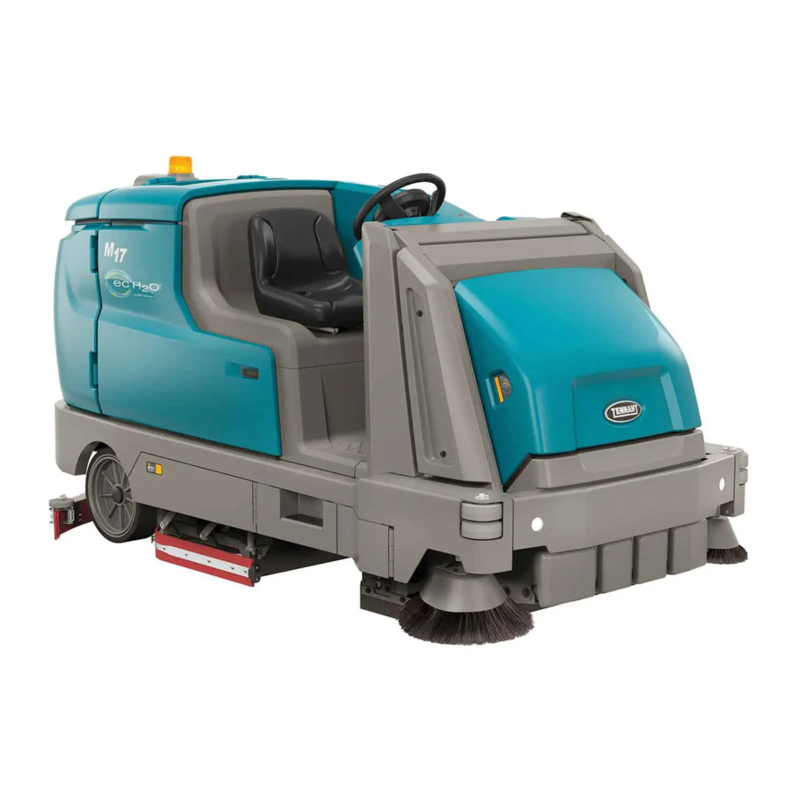
- Page 2 INTENDED USE The M17 is an industrial rider machine designed to wet scrub and sweep both rough and smooth hard surfaces (concrete, tile, stone, synthetic, etc). Typical applications include schools, hospitals / health care facilities, off ce buildings, and retail centers. Do not use this machine on soil, grass, artif cial turf, or carpeted surfaces.
-
Page 3: Table Of Contents
. . . . . 3-49 prIMING THE ec-H2O SYSTEM . . . . . . . . . . . 3-51 M17 Service Information 9017358 (08-2016) - Page 4 InSTaLLaTIon . . . . . . . . . . . . . . . . . . . . 5-15 M17 Service Information 9017358 (08-2016)
-
Page 5: Safety Precautions
Tennant representative for information on how to disable the cellular communication functionality. CAUTION: To warn of unsafe practices that could result in minor or moderate personal injury. - Page 6 - Do not modify the machine from its original - Always follow safety and traffic rules. design. - Report machine damage or faulty operation - Use Tennant supplied or approved immediately. replacement parts. - Follow mixing, handling and disposal - Wear personal protective equipment as instructions on chemical containers.
- Page 7 - Do not load/unload on ramp inclines that exceed 20% grade. - Use winch. Do not push the machine onto/off the truck or trailer unless the load height is 380 mm (15 in) or less from the ground. M17 Service Information 9017358 (08-2016)
- Page 8 Do not carry passengers on any part of the machine. Located on rear bumper door / step. FOR SAFETY LABEL - Authorized Service Mechanic Only. Located on circuit board cover and electrical panel. M17 Service Information 9017358 (08-2016)
- Page 9 Located on bottom of battery compartment cover. FOR SAFETY LABEL - Read manual before operating machine. WARNING LABEL - Raised hopper may fall. Engage hopper support bar. Located on hopper support bar. Located on electrical panel. M17 Service Information 9017358 (08-2016)
- Page 10 SAFETY PRECAUTIONS M17 Service Information 9017358 (08-2016)
-
Page 11: General Information
SyStem (option) . . . . . . . . . . . . . 2-19 eLeCtriCaL ComponentS . . . . . . . . . . . . 2-20 M17 Service Information 9017358 (08-2016) -
Page 12: Component Locator
Switch, eS half-full Switches* rear Squeegee Lift actuator brake adjustment rods Scrub head Lift actuator brake pedal interlock Switch Control modules, m1 Contactor Circuit breakers (1-9) Seat Switch battery rollout Switch * optional equipment M17 Service Information 9017358 (08-2016) -
Page 13: Component Locator
Side Scrub brush Lift actuator Electrical Sweeping motor Control Box throttle Sensor Shaker Sweep System Sweeping, filter Hopper Lift Cylinder and Roll-Out Actuator Hopper Lift Pump & Reservoir Sweeper, hopper Side Sweep brush motors * optional equipment M17 Service Information 9017358 (08-2016) - Page 14 J9-6 HALL_1_RT 208/GRY MTR_3/W J9-7 HALL_2_RT FRONT CIRCUIT BREAKER PANEL 130/TAN J9-8 105/GRN HALL_1 HALL_3_RT J9-9 131/PNK STATIC GROUNDING HALL_2 +5VDC_RT (PART OF MAIN HARNESS) J9-10 132/BRN HALL_3 GND_RT 133/ORA +5VDC SCRUB MODULE OPEN2 134/YEL M17 Service Information 9017358 (08-2016)
- Page 15 13/BLK SHAKER MTR. CB-20 105/GRN 195/GRN 13/BLK DRY VAC MTR. 40A-SWEEP MTR-27 STATIC GROUNDING (PART OF SWEEP HARNESS) J4-8 187/PUR D_VAC_REF 188/GRY J4-3 D_VAC_RPM_IN 13/BLK PARTIAL OPT: DRY VAC HARNESS SIDE SWEEP/VAC MODULE 13/BLK 13/BLK M17 Service Information 9017358 (08-2016)
- Page 16 +36VDC FROM CONTROLLER REVERSE ALARM 2.5A 85/GRN-WHT LOCATED INSIDE 90/TAN LIGHT ASSEMBLY NOT USED LT-5 (FOR SPECIALS) WHT, BACK UP LIGHT (LED) 90/TAN 15/GRN OPT. LIGHT KIT OPT. LIGHT / ALARM HARNESS OPT. REVERSE RELAY M17 Service Information 9017358 (08-2016)
-
Page 17: Electrical Schematic Symbols
Induction Motor Energized Relay Coil Adaptor Harness Motor Encoder N.C. Relay Contacts Sensor (Variable Resistor) Notes Momentary Switch N.O. N.O. Relay Contacts Assembly Contact Switch N.C. Horn or Alarm AC Plug Solenoid Valve Capacitor Light M17 Service Information 9017358 (08-2016) -
Page 18: Operational Matrix
J11-6, J9-6, 10 Low J9-7, J9-8, Solution tank empty Scrub mod- J9-9, J9-10 ule, J4-1 ≈ < 0.73 Vdc Low battery Voltage Curtis pmC module, J1-1 ≈ < 32 Vdc Circuit fault Can-bus to interface module M17 Service Information 9017358 (08-2016) - Page 19 - ready State Curtis pmC, right motor mand J1-6 ≈ J1-6 ≈ 0 Vdc J3-2 CB-17, 0.2-5 vDC Low battery Voltage Curtis pmC J4-16 module, J1-1 ≈ < 32 Vdc Can-bus to Circuit fault interface module M17 Service Information 9017358 (08-2016)
- Page 20 J6- 10 Low Solution tank empty Scrub mod- ule, J4-1 ≈ < 0.73 Vdc Low battery Voltage Curtis pmC module, J1-1 ≈ < 32 Vdc Circuit fault Can-bus to interface module 2-10 M17 Service Information 9017358 (08-2016)
- Page 21 J5-5 and J5-6 = Closed System over pressure ec-h2o mod- (≈ > 20 psi) ule, J4-9 = Not Grounded Severe environment Scrub mod- mode ule, J4-8 Low or J4-7 Low 2-11 M17 Service Information 9017358 (08-2016)
- Page 22 J6- 10 = Ground Solution tank empty Scrub mod- ule, J4-1 ≈ < 0.73 Vdc Low battery Voltage Curtis pmC module, J1-1 ≈ < 32 Vdc Circuit fault Can-bus to interface module 2-12 M17 Service Information 9017358 (08-2016)
- Page 23 1-STEP On 1-STEP Off Main Sweep/ Sweeper interface Actuator Lift module: module, module: actuator J6-1 = Not Can-bus J4-16, J4-17 Grounded interface Main Sweep Selected Main Sweep Deselected Can-bus to module, interface Can-bus module 2-13 M17 Service Information 9017358 (08-2016)
-
Page 24: Faults
. Filter Shaker Filter Shaker Button Off Main Sweep/ Filter Shaker Button On Lift Module 1-Step On Main Sweep Deselected J4-15, J4-11, CB-17 Dust Vacuum Deselected Sweep Function Enabled 1-Step Off 2-14 M17 Service Information 9017358 (08-2016) -
Page 25: Fastener Torque
508 - 660 nm 177 - 230 nm 409 - 530 nm 574 - 745 nm 686 - 890 nm 227 - 295 nm 520 - 675 nm 732 - 950 nm 879 - 1140 nm M17 Service Information 9017358 (08-2016) 2-15... -
Page 26: Machine Dimensions
1405 mm (55.3 in) 1700 mm (67 in) 2096 mm (82.5 in) 1480 mm (58.25 in) Track Wheel base (at rear wheels) 1163 mm 1041 mm (46 in) (41 in) 2850 mm (112.1 in) 2-16 M17 Service Information 9017358 (08-2016) - Page 27 3 dB Sound power level LWA + Uncertainty KWA 94.63 dB + 2.98 dB 94.63 dB + 2.98 dB Vibration - Hand-arm <2.5 m/s <2.5 m/s <0.5 m/s <0.5 m/s Vibration - Whole body 2-17 M17 Service Information 9017358 (08-2016)
-
Page 28: General Machine Performance
Side sweep brush 0.06 (0.08) Vacuum fan (sweep) 0.85 (1.10) Vacuum fan (scrub) 0.6 (0.80) Propelling 2.25 (3.00) Type Phase Charger (Smart) 50-60 200-240 Charger (Smart) 50-60 380-415 Charger (Smart) 50-60 480-600 Charger (Opportunity) 50-60 2-18 M17 Service Information 9017358 (08-2016) -
Page 29: Tires
Solution flow rate (machines with Up to 2.65 LPM (0.70 GMP) - To main scrub head optional scrubbing side brush) Up to 1.14 LPM (0.30 GPM) - To scrubbing side brush 2-19 M17 Service Information 9017358 (08-2016) -
Page 30: Electrical Components
0 .5 - 1 .5 amps Severe environment Valve, ec-h2o Side brush 129 Ω +/- 5% Valve, Conventional Side brush 108 Ω +/- 10% Valve, Conventional main brush 108 Ω +/- 10% Valve, autofill 218 Ω +/- 10% 2-20 M17 Service Information 9017358 (08-2016) -
Page 31: Disabling / Enabling The Pre- Operation Checklist
TIME ........3-66 M17 Service Information 9017358 (08-2016) - Page 32 MAINTENANCE MAINTENANCE M17 Service Information 9017358 (08-2016)
-
Page 33: Maintenance Chart
Check brush pattern LUBRICANT/FLUID Distilled water. Special lubricant, Lubriplate EMB grease (Tennant part number 01433-1) SAE 90 weight gear lubricant HYDO Tennant True premium hydraulic fluid or equivalent NOTE: More frequent maintenance intervals may be required in extremely dusty conditions. - Page 34 HYDO Hours LUBRICANT/FLUID Distilled water. Special lubricant, Lubriplate EMB grease (Tennant part number 01433-1) SAE 90 weight gear lubricant HYDO Tennant True premium hydraulic fluid or equivalent NOTE: More frequent maintenance intervals may be required in extremely dusty conditions. M17 Service Information 9017358 (08-2016)
-
Page 35: Yellow Touch Points
200 hours. HOPPER CHAINS The hopper chains are located on the left hand side of the machine. Check for damage or wear and lubricate the hopper chains after every 200 hours.. M17 Service Information 9017358 (08-2016) -
Page 36: Hopper Chains
With the hopper in the lowered position; the longer arm chain (A) should not move more than 25 mm (1 in) and the shorter lintel chain (B) should not move more than 12 mm (0.5 in). M17 Service Information 9017358 (08-2016) -
Page 37: Hydraulics
Damage to the machine hydraulic system may result. Drain and refill the hydraulic fluid reservoir with new TennantTrue premium hydraulic fluid after every 2400 hours of operation. M17 Service Information 9017358 (08-2016) - Page 38 Consult a physician immediately if injury results from escaping hydraulic fluid. Serious infection or reaction can occur if proper medical treatment is not given immediately. Contact a mechanic or supervisor if a leak is discovered. M17 Service Information 9017358 (08-2016)
- Page 39 Allow the charger to completely charge the battery before re using the machine. NOTE: Make sure the battery caps are in place while charging. There may be a sulfur smell after charging batteries. This is normal. M17 Service Information 9017358 (08-2016)
- Page 40 Replace any worn or damaged wires. Do not remove battery caps when cleaning batteries. 3-10 M17 Service Information 9017358 (08-2016)
- Page 41 NOTE: If there are charger fault codes when the battery is plugged into the battery charger, the fault codes will appear at the bottom of the charger display. Refer to the battery charger manual for fault code def nitions 3-11 M17 Service Information 9017358 (08-2016)
- Page 42 COMPLETE will appear in the display, all the G. Charging phase (Phase 1 / Phase 2 / Phase charger status indicators will be illuminated, 3 / Maintenance) and the Tennant charger will stop charging when the battery is completely charged. 3-12 M17 Service Information 9017358 (08-2016)
- Page 43 Arcing may result. If the charger must be interrupted during charging, disconnect the AC power supply cord first. 13. Close the battery compartment top cover. 3-13 M17 Service Information 9017358 (08-2016)
- Page 44 Arcing may result. If the charger must be interrupted during charging, press charger stop / start button to stop charger. 8. Disconnect the charger connector from the battery cable connector. 3-14 M17 Service Information 9017358 (08-2016)
- Page 45 NOTE: Sunday is the default day for the charger to conduct a full equalization charge to the battery. The default day can be changed to another day if necessary. Consult a Tennant service representative about changing the default day. Allow the charger to fully complete the equalization charge.
- Page 46 NOTE: The water supply to the battery water system must always be 7.57 LPM (2 GPM) or more. Use the purger to conf rm the water supply pressure. Refer to manufacturer Operator Manual for additional information. M17 Service Information 9017358 (08-2016) 3-16...
-
Page 47: Circuit Breakers, Fuses, And Relays
(Option) CB15 Power steering (Option) CB16 Lift module CB17 Sweep module CB18 Sweep vacuum 1 CB19 Sweep vacuum 2 CB20 Dry vacuum (Option) CB21 2.5A Alarm / Flashing light (Option) 3-17 M17 Service Information 9017358 (08-2016) -
Page 48: Electric Motors
Refer to the table below for the relays and circuits controlled. Relay Rating Circuit Controlled 36 VDC, 200 A Main contactor 36 VDC, 5 A Backup alarm / light (Option) 36 VDC, 100 A Auxiliary line contactor 36 VDC, 200A Sweep contactor 3-18 M17 Service Information 9017358 (08-2016) -
Page 49: Hopper Dust Filter/Perma-Filter
5. Clean dust and debris from the dust filter tray. See CLEANING THE HOPPER DUST FILTER. 2. Remove the dust filter cover. 6. Reinstall the dust filter. 7. Reinstall the dust filter cover. 8. Reinstall the hopper cover. 3-19 M17 Service Information 9017358 (08-2016) - Page 50 If there is a fire in the hopper, the Thermo-Sentry stops the vacuum fan and cuts off the air flow. The Thermo-Sentry automatically resets after cooling down. 3-20 M17 Service Information 9017358 (08-2016)
-
Page 51: Main Scrub Brushes
REPLACING DISK SCRUB BRUSHES OR PAD DRIVERS 1. Raise the scrub head. 2. Turn off the machine. FOR SAFETY: Before leaving or servicing machine, stop on level surface, turn off machine, set parking brake, and remove key. 3-21 M17 Service Information 9017358 (08-2016) - Page 52 9. Close and secure the squeegee support door driver. and close the main brush access door. 5. Reinstall the pad driver onto the machine. 10. Repeat procedure for the other brushes. M17 Service Information 9017358 (08-2016) 3-22...
- Page 53 6. If rotating the brushes, always rotate the front the retainer ring from the idler plate hook. with the back so that they wear evenly. They may be rotated end for end as well. Before After 3-23 M17 Service Information 9017358 (08-2016)
- Page 54 9. Close and secure the squeegee support door and close the main brush access door. 10. Repeat for the brush on the other side of the scrub head. 3-24 M17 Service Information 9017358 (08-2016)
-
Page 55: Main Sweep Brushes
6. Slide the brushes into the main sweep brush compartment and all the way onto the drive hubs. 7. Reinstall the main sweep brushes idler plate. 8. Close the main sweeping brush compartment access door. 3-25 M17 Service Information 9017358 (08-2016) -
Page 56: Side Brushes
9 o’clock and 2 o’clock when the brushes are in motion. 3. Remove the side brush and retainer from under the side brush assembly. 350327 3-26 M17 Service Information 9017358 (08-2016) - Page 57 The selected side brush will lower and spin. NOTE: Contact a Tennant service representative if there is a f at pattern (full circle) after the sweeping side brushes have been adjusted. 4. Observe the brush pattern...
- Page 58 9. Recheck the brush patterns. Adjust brush pressure as necessary. NOTE: Contact a Tennant service representative if 4. Press the desired sweeping side brush button there is a f at pattern (full circle) after the sweeping to adjust it.
- Page 59 6. Place the new side brush underneath the side brush assembly and lift the side brush up onto the side brush hub until the brush locks onto the hub. 7. Reinstall the scrubbing side brush squeegee assembly. 3-29 M17 Service Information 9017358 (08-2016)
-
Page 60: Squeegee Blades
FOR SAFETY: Before leaving or servicing machine, stop on level surface, turn off machine, set parking brake, and remove key. 2. Disconnect the vacuum hose from the rear squeegee assembly 4. Pull the rear squeegee assembly from the machine. 3-30 M17 Service Information 9017358 (08-2016) - Page 61 8. Insert the hinge end of the retainer into the hooks in the rear squeegee assembly. 6. Remove the rear squeegee from the squeegee assembly. 3-31 M17 Service Information 9017358 (08-2016)
- Page 62 12. Remove the front squeegee from the squeegee assembly. 10. Turn the rear squeegee assembly over to access the front of the squeegee assembly. 3-32 M17 Service Information 9017358 (08-2016)
- Page 63 14. Install the front squeegee retainer onto the rear squeegee assembly. 15. Reinstall the rear squeegee assembly onto the machine 16. Raise the rear bumper door / step if it was lowered to access the rear squeegee assembly. 3-33 M17 Service Information 9017358 (08-2016)
- Page 64 5. To adjust the squeegee leveling, loosen the tilt if adjustments were made. lock knob. 9. Readjust the squeegee blade deflection if necessary. 10. Raise the Rear bumper door / step when finished leveling the rear squeegee. 3-34 M17 Service Information 9017358 (08-2016)
- Page 65 8. Readjust the squeegee blade deflection if 3. Lower the rear bumper door / step. necessary. 9. Raise the rear bumper door / step when finished adjusting the rear squeegee blade deflection. 3-35 M17 Service Information 9017358 (08-2016)
- Page 66 4. Remove the retaining band from the side squeegee assembly. 9. Close and secure the squeegee support door and close the main brush access door. 10. Repeat for the side squeegee on the other side of the scrub head. 3-36 M17 Service Information 9017358 (08-2016)
- Page 67 Install / reinstall squeegees so the def ection is approximately 12 mm (0.50 in) for smooth f oors and 15 mm (0.62 in) for rough f oors. 3-37 M17 Service Information 9017358 (08-2016)
- Page 68 Be sure the holes in the squeegee blade are hooked onto the tabs. 6. Reinstall the side brush squeegee assembly onto the side brush assembly. 3-38 M17 Service Information 9017358 (08-2016)
-
Page 69: Skirts And Seals
The side skirts are located on both sides of the main sweeping brushes. The side skirts should be just touching the floor. Check the skirts after every 50 hours of operation for damage and wear. 3-39 M17 Service Information 9017358 (08-2016) - Page 70 50 hours of operation. HOPPER DUST FILTER SEAL Check the hopper dust filter cover seal for wear or damage every 100 hours of operation. Clean dust and debris from the seal as necessary. 3-40 M17 Service Information 9017358 (08-2016)
- Page 71 The machine has three solid rubber tires: one in for damage and wear after every 200 hours of front, and two in the rear of the machine. Check operation. tires for damage and wear after every 500 hours of operation. 3-41 M17 Service Information 9017358 (08-2016)
-
Page 72: Pushing, Towing, And Transporting
Do not drive the machine onto the truck or trailer unless the loading surface is horizontal AND is 380 mm (15 in) or less from the ground. 5. Back the machine onto the trailer or truck. 3-42 M17 Service Information 9017358 (08-2016) - Page 73 AND 380 mm (15 in) or less from the ground. 9. Lower the hopper, scrub head, and rear squeegee. 3-43 M17 Service Information 9017358 (08-2016)
-
Page 74: Machine Jacking
FOR SAFETY: When servicing machine, block machine tires before jacking machine up. Use a hoist or jack that will support the weight of the machine. Jack machine up at designated locations only. Support machine with jack stands. 3-44 M17 Service Information 9017358 (08-2016) -
Page 75: Ec-H2O Module Flush Procedure
6. Pour 2 gallons (7.6 liters) of white or rice hose. vinegar into the solution tank. 3. Remove the drain hose from the ec-H2O compartment. 3-45 M17 Service Information 9017358 (08-2016) - Page 76 11. Disconnect the drain hose from the ec-H2O manifold hose. 12. Reconnect the outlet hose to the ec-H2O manifold hose. 13. Return the drain hose to storage location in the ec-H2O compartment. 14. Close the right shroud. 3-46 M17 Service Information 9017358 (08-2016)
-
Page 77: Storage Information
6. Repeatedly press the solution increase button 2. Pour 7.6 L (2 gal) of Propylene Glycol Based (+) until the solution flow is at the highest / Recreational Vehicle (RV) antifreeze into the setting. solution tank. Standard Panel Pro-Panel 3-47 M17 Service Information 9017358 (08-2016) - Page 78 Standard Panel Pro-Panel 8. Machines with scrubbing side brush option only: Press the scrubbing side brush button to activate the side brush. Standard Panel Pro-Panel 3-48 M17 Service Information 9017358 (08-2016)
-
Page 79: Preparing The Machine For
Pour 1.9 L (1/2 gal) of cool clean equipped with ec-H2O must be primed before the water into the detergent tank. machine is ready for operation. See PRIMING THE ec-H2O SYSTEM for additional instructions. 5. Turn on the machine. 3-49 M17 Service Information 9017358 (08-2016) - Page 80 14. Press the 1-STEP button to turn off the system. 15. Turn off the machine. Standard Panel Pro-Panel 9. Machines with scrubbing side brush option only: Press the side brush switch to activate the side brush. Standard Panel Pro-Panel 3-50 M17 Service Information 9017358 (08-2016)
-
Page 81: Priming The Ec-H2O System
2. Open the right shroud to access the ec-H2O assembly. 3. Press the connector button to disconnect the outlet hose from the ec-H2O manifold. 6. Place the drain hose into a empty container. 3-51 M17 Service Information 9017358 (08-2016) - Page 82 10. Disconnect the drain hose from the ec-H2O manifold hose. 11. Reconnect the outlet hose to the ec-H2O manifold hose. 12. Place the drain hose back into the ec-H2O compartment. 13. Close the right shroud. 3-52 M17 Service Information 9017358 (08-2016)
-
Page 83: Supervisor Controls
1. Turn on the machine. The main operating button to access the supervisor settings screen will appear in the display.. screen. 2. Press the help button to access the help screen. 6. Proceed to ADDING / EDITING PROFILES. 3-53 M17 Service Information 9017358 (08-2016) -
Page 84: Entering The Supervisor Mode
Press the backspace button if necessary to delete and reenter a number. 3. The supervisor machine operation screen should appear in the display. Press the settings button to access the supervisor settings screen. 3-54 M17 Service Information 9017358 (08-2016) -
Page 85: Supervisor Setting Screen / Screen Icons
See CHANGING REARVIEW CAMERA SETTINGS. Press the back button to navigate back to the previous screen. Press the SYSTEM TIME button to access the date / time screen. See SETTING / CHANGING THE TIME AND DATE. 3-55 M17 Service Information 9017358 (08-2016) -
Page 86: Adding / Editing Profiles
Press the Delete Profile button to delete an existing profile. Press the home button to navigate back to the main operating screen. Press the back button to navigate back to the previous screen. 3-56 M17 Service Information 9017358 (08-2016) - Page 87 Press the mph button to set the machine speed to miles per hour. Press the km/h button to set the machine speed to kilometers per hour. Press the enter button to set the maximum speed for the machine. 3-57 M17 Service Information 9017358 (08-2016)
-
Page 88: Enabling The Login
Turning the key to the off position is another way to also logout. 13. Use the Edit Profile button, Copy Profile button, and Delete Profile button to manage the current user profiles. 3-58 M17 Service Information 9017358 (08-2016) -
Page 89: Disabling The Login
3. Press the yes button to enter the Default User screen. 4. Press either the Operator button or Supervisor button to select the desired default user. 3-59 M17 Service Information 9017358 (08-2016) -
Page 90: Changing Battery Type
1. Turn on the machine, login to the main operation screen, and press the setting button to access the supervisor settings screen. See ENTERING THE SUPERVISOR MODE. 2. Press the Calibrate Touch button to recalibrate touch. If the touch points become misaligned. M17 Service Information 9017358 (08-2016) 3-60... -
Page 91: Exporting Checklists
Press the home button to navigate back to the export screen. the main operating screen. Press the back button to navigate back to the previous screen. 5. Remove the flash drive from USB port and turn off the machine. 3-61 M17 Service Information 9017358 (08-2016) - Page 92 Press the home button to navigate back to the main operating screen. Press the down arrow button to scroll down through Pre-Operation Checklist Press the back button to navigate back to items. the previous screen. 3-62 M17 Service Information 9017358 (08-2016)
- Page 93 2. Press the Checklist Setup button to access the Pre-Operation Checklist setup screen. Press the home button to navigate back to the main operating screen. Press the back button to navigate back to the previous screen. 3-63 M17 Service Information 9017358 (08-2016)
- Page 94 Press the home button to navigate back to the main operating screen. Press the back button to navigate back to the previous screen. 3-64 M17 Service Information 9017358 (08-2016)
- Page 95 Press the backspace button if necessary to delete and reenter a number. Press the space button to place space between letters / numbers. Press the pound button to toggle between the number keypad and the letter keypad. 3-65 M17 Service Information 9017358 (08-2016)
-
Page 96: Time
Press the back button to navigate back to the previous screen. 3. Press the home button when finished setting / changing the system date and time to return to the main operating screen. 3-66 M17 Service Information 9017358 (08-2016) -
Page 97: Troubleshooting Onboard Diagnostics
MIDDLE SWEEP BRUSH MOTORS 4-80 ..SHAKER MOTOR 4-82 ..... . DRY VACUUM FAN 4-84 M17 Service Information 9017358 (08-2016) -
Page 98: Self-Test Mode
Operational Matrix: Enabled Enabled Disabled • 1-STEP Scrub ON • Fwd/Rev Propel Scrub Head • 1-STEP Scrub ON • 1-STEP Scrub OFF M17 Service Information 9017358 (08-2016) Scrub Head • Squeegee/Vac ON • Squeegee/Vac OFF Down Down • Recovery Tank Full... - Page 99 Note: LCD Message's above can be seen as an open Testing Ec-H2O Pump... or a short. Testing ES Pump. Testing Side Valve.. Testing Solution Auto-Fill Valve.. Testing Recovery Auto-Fill Valve.. Testing Horn... Testing Alarm... Test Propel CAN Communication... M17 Service Information 9017358 (08-2016)
-
Page 100: Configuration Mode
• 1-STEP Scrub ON • Fwd/Rev Propel Scrub Head • 1-STEP Scrub ON • 1-STEP Scrub OFF Scrub Head M17 Service Information 9017358 (08-2016) • Squeegee/Vac ON • Squeegee/Vac OFF Down Down • Recovery Tank Full • Low Batt Voltage... - Page 101 Resets scrub head type, solution configuration, down pressure targets, flow range, side option, travel speeds, autofill option, SE option to default settings. C21:Battery Type Configure battery type. Configure dust vacuums C22:Dust Vac C23:Side Sweep Configure side sweep motors M17 Service Information 9017358 (08-2016)
- Page 102 If connections check out, replace motor. control board. 1. Shorted load condition 0x0122 S Scrub Vlt Side Scrub Motor Voltage Loss 1. Check wire harness and repair as needed. 2. Some higher current draw than hardware design limit. M17 Service Information 9017358 (08-2016)
- Page 103 2. Replace Control Board. 0x0240 RSwpAct Flt Right Sweep Actuator Generic 1. Control board problem. 1. Check voltage references. 0x0247 RSwpAct FET Right Sweep Actuator FET Fault 2. Power/battery issue on startup. 2. Replace Control Board. M17 Service Information 9017358 (08-2016)
- Page 104 1. Check connections, board gets power from key 1. Wiring, connector or control board issue with circuit to 0x0341 SAF Vlv Opn Solution AutoFill Valve Open Warning switch and battery. If connections check out, replace motor. control board. M17 Service Information 9017358 (08-2016)
- Page 105 1. Check connections, board gets power from key 1. Wiring, connector or control board issue with circuit to 0x0621 ES Pump Opn Extended Scrub Pump Open Warning switch and battery. If connections check out, replace motor. control board. M17 Service Information 9017358 (08-2016)
- Page 106 0x07A2 Hopper not in Home position 1. Hopper not completely lowered. 2. Check system for binding. 0x1003 Down Pressure Unattainable 0x2000 Pascal Flt Touchscreen Error 1. Touchscreen control board problem. 1. Replace Touchscreen board. 4-10 M17 Service Information 9017358 (08-2016)
-
Page 107: Propel Diagnostic Mode
STP002 CONFIG MODE Operational Matrix: Operational Matrix: Enabled Enabled Disabled • 1-STEP S 4-11 M17 Service Information 9017358 (08-2016) • Fwd/Rev • 1-STEP Scrub ON • 1-STEP Scrub OFF Scrub Head Scrub Head • Squeegee/Vac ON • Squeegee/Vac OFF Down Down •... - Page 108 • Fwd/Rev Propel • 1-STEP Scrub ON • 1-STEP Scrub OFF Scrub Head Scrub Head • Squeegee/Vac ON • Squeegee/Vac OFF Down Down • Recovery Tank Full • Low Batt Voltage • Load Current Fault 4-12 M17 Service Information 9017358 (08-2016)
-
Page 109: Diagnostics
The red LED flashes twice to indicate that the second digit of the code will follow; the yellow LED flashes the appropriate number of times for the second digit. Example: Battery Undervoltage (Code 23) YELLOW YELLOW (first digit) (second digit) 4-13 M17 Service Information 9017358 (08-2016) -
Page 110: Diagnostic Codes
4. Battery disconnected while driving. 5. See Monitor menu » Battery: Capacitor Voltage. 6. Blown B+ fuse or main contactor did not close. PMC003 Terms: KSI = Key Switch Interlock FET = Field-Effect Transistor 4-14 M17 Service Information 9017358 (08-2016) - Page 111 15 mA. will not turn on. Clear: Remedy the overcurrent cause and use the VCL function Set_DigOut() to turn the driver on again. PMC004 Terms: KSI = Key Switch Interlock FET = Field-Effect Transistor 4-15 M17 Service Information 9017358 (08-2016)
- Page 112 2. Dirty connector pins. shorted. ShutdownDriver4. 3. Bad crimps or faulty wiring. Clear: Correct open or short, and cycle driver. Terms: KSI = Key Switch Interlock FET = Field-Effect Transistor VCL = Vehicle Control Language PMC005 4-16 M17 Service Information 9017358 (08-2016)
- Page 113 2. Pot2 wiper voltage too high. (can be changed with the VCL function Setup_Pot_Faults()). Clear: Bring Pot2 wiper voltage below the fault threshold. Terms: KSI = Key Switch Interlock PMC006 FET = Field-Effect Transistor VCL = Vehicle Control Language 4-17 M17 Service Information 9017358 (08-2016)
- Page 114 Clear: Release throttle and properly sequence key switch, seat switch and then throttle. Action: Throttle Shutdown. Terms: KSI = Key Switch Interlock PMC007 FET = Field-Effect Transistor VCL = Vehicle Control Language 4-18 M17 Service Information 9017358 (08-2016)
- Page 115 Action: Speed Limit is set to "Fault Timeout Period" parameter (2.5 sec). Max Speed" parameter (311 rpm) The CAN engine has been set to a "non- Set: Tennant Master Controller set to non- operational" state by the Tennant Master operation. Controller. An NMT message of the...
- Page 116 7=severe overvoltage fault 8=encoder signal not seen, or one or both channels missing 9=motor parameters out of character- ization range. Terms: PMC009 KSI = Key Switch Interlock FET = Field-Effect Transistor VCL = Vehicle Control Language 4-20 M17 Service Information 9017358 (08-2016)
- Page 117 ShutdownThrottle; Clear: Download appropriate software 3. Controller defective. FullBrake; for your controller model. ShutdownPump. Terms: PMC010 KSI = Key Switch Interlock FET = Field-Effect Transistor EMR = Emergency Reverse 4-21 M17 Service Information 9017358 (08-2016)
-
Page 118: Input Display Mode
Disabled • 1-STEP Scrub ON • Fwd/Rev Propel Scrub Head • 1-STEP Scrub ON • 1-STEP Scrub OFF 4-22 M17 Service Information 9017358 (08-2016) Scrub Head • Squeegee/Vac ON • Squeegee/Vac OFF Down Down • Recovery Tank Full • Low Batt Voltage... - Page 119 I4:Seat Switch: Seated I5:Shaker Switch I10: SE Switch Off/On Off/On IDM003 6. Press any other touch panel button to display a corresponding LCD text message. The message confirms that the control board received the input. 4-23 M17 Service Information 9017358 (08-2016)
-
Page 120: Manual Mode
CONFIG MODE Operational Matrix: Operational Matrix: Enabled Enabled Disabled • 1-STEP Scrub ON 4-24 M17 Service Information 9017358 (08-2016) • Fwd/Rev Propel • 1-STEP Scrub ON • 1-STEP Scrub OFF Scrub Head Scrub Head • Squeegee/Vac ON • Squeegee/Vac OFF... - Page 121 (X.XXX) XXX% XX.XXA M23: Ec Cell M35: Fact Set Roll? M11: Wtr Vac 1 XXX% XX.XA X.XXX (X.XXX) XXX% XX.XXA M12: Wtr Vac 2 M24: Scrub Act Exit Manual Mode XXX% XX.XA XXX.X% XX.XA 4-25 M17 Service Information 9017358 (08-2016)
-
Page 122: Motors Mode
• Fwd/Rev Propel Scrub Head • 1-STEP Scrub ON • 1-STEP Scrub OFF Scrub Head • Squeegee/Vac ON • Squeegee/Vac OFF Down 4-26 M17 Service Information 9017358 (08-2016) Down • Recovery Tank Full • Low Batt Voltage • Load Current Fault... - Page 123 MM4: Side Sweep MM5: All Sweep MM6: Run Ec-H2O Exit Motors Mode Operational Matrix: Enabled Disa • 1-STEP Scrub ON • 1- Scrub Head • Squeegee/Vac ON • Sq 4-27 M17 Service Information 9017358 (08-2016) Down • Re • Lo • Lo...
- Page 124 TROUBLESHOOTING 4-28 M17 Service Information 9017358 (08-2016)
- Page 125 Derate Level 1, Up to 75% of Maximum Torque Blinking Output Yellow, Derate Level 2, Up to 50% of Maximum Torque Blinking Output Red, Derate Level 3, Up to 20% of Maximum Torque Blinking Output 4-29 M17 Service Information 9017358 (08-2016)
-
Page 126: Back-Up Alarm/Light
Operational Matrix: Enabled Disabled Battery Positive + • Rev Switch Input • Fwd Switch Input Back-Up Battery Negative - • • Neutral - Ready Rev Throttle Command Alarm/Lights State • Curtis 1232SE Fault PMC011 4-30 M17 Service Information 9017358 (08-2016) - Page 127 Is there battery voltage applied? Terms: Backprobe = To insert voltmeter probe(s) into the back of a connector to contact a terminal(s) while the circuit operates or should be operating. VDC = DC Voltage 4-31 M17 Service Information 9017358 (08-2016)
-
Page 128: Lighting
Headlight and Warning ON/Up = 3-4, 7-8 CB11 CB12 (2.5A) 67/PUR (15A) 65/GRN CB13 (2.5A) 68/GRY 93/ORA 13/BLK OHG Flash/ CB14 Strobe Light (2.5A) 92/BRN 13/BLK Flash/Strobe Light Battery Positive + Battery Negative - ELC001 4-32 M17 Service Information 9017358 (08-2016) - Page 129 Test voltage applied to the lighting subsystem as Location and shown on the electrical schematic Repair or Re- • Are the electrical circuits operating as shown on the place Neces- electrical schematic? sary Compo- nents 4-33 M17 Service Information 9017358 (08-2016)
-
Page 130: Main Scrub Brushes
J9-7 HALL 2 CAN + 130/TAN J9-6 HALL 1 J1-1 J11-5 RT MTR 2 Twisted 204/YEL Pair J11-6 RT MTR 3 208/GRY J11-4 RT MTR 1 205/GRN Battery Positive + Battery Negative - MSC001 4-34 M17 Service Information 9017358 (08-2016) - Page 131 J5-5 = T12 Scrub Module Connector #5, Pin #5 J5-4 = T12 Scrub Module Connector #5, Pin #4 J5-2 = T12 Scrub Module Connector #5, Pin #2 J5-1 = T12 Scrub Module Connector #5, Pin #1 4-35 M17 Service Information 9017358 (08-2016)
-
Page 132: Side Scrub Brush
• Side Brush Switch ON Brush On/ • Recovery Tank Full Battery Positive + • Solution Tank Empty Down • Very Low Batt Voltage Battery Negative - • Circuit Fault • Neutral (Ready State) SBC004 4-36 M17 Service Information 9017358 (08-2016) - Page 133 Terms: J4-7, 8 = Side Scrub Module Connector #4, Pin #7 or 8 J6-1, 2, 3 = Side Scrub Module Connector #6, Pin #1, 2, or 3 4-37 M17 Service Information 9017358 (08-2016)
-
Page 134: Power-Up
M17 Scrub FUSE-2 Module 100A BUS BAR 16/BLU P1-1 (B+) Post J4-18 Key Switch (B+) 8/GRY P2-1 (B-) Post Instrument Panel Assembly Tennant M17 UI ver X.X Battery Positive + PUC001 Battery Negative - 4-38 M17 Service Information 9017358 (08-2016) - Page 135 Drop shown on the electrical schematic Location and • Are the electrical circuits operating as shown on the Repair or Re- electrical schematic? place Neces- sary Compo- nents Terms: VDC = DC Voltage 4-39 M17 Service Information 9017358 (08-2016)
-
Page 136: Propel
• Seat Switch Open • Foot Throttle • Neutral-Ready Propel Command State Battery Positive + • Fwd/Rev Switch Input • Park Brake Set • Rollout Door Open Battery Negative - • Curtis 1232SE Fault PMC014 4-40 M17 Service Information 9017358 (08-2016) - Page 137 Test voltage applied to the propel subsystem as place Neces- shown on the electrical schematic sary Compo- • Are the electrical circuits operating as shown on the nents electrical schematic? Terms: VDC = Direct Current Voltage 4-41 M17 Service Information 9017358 (08-2016)
- Page 138 • 1-STEP Scrub OFF • Squeegee/Vac ON • Squeegee/Vac OFF Squeegee Battery Positive + • Reverse Propel Down • Recovery Tank Full Battery Negative - • Very Low Batt Voltage • Circuit Fault RSL001 4-42 M17 Service Information 9017358 (08-2016)
-
Page 139: Rear Squeegee Lift
• Are the electrical circuits operating as shown on the sary Compo- electrical schematic? nents Terms: J5-3 = Water PU Module Connector #5, Pin #3 J5-2 = Water PU Module Connector #5, Pin #2 4-43 M17 Service Information 9017358 (08-2016) -
Page 140: Scrub Head Lift
• 1-STEP Scrub OFF • Fwd/Rev Propel • Neutral-Ready State Scrub Head Battery Positive + • Recovery Tank Full Down • Solution Tank Empty Battery Negative - • Very Low Batt Voltage • Circuit Fault MSL001 4-44 M17 Service Information 9017358 (08-2016) - Page 141 Neces- • Are the electrical circuits operating as shown on the sary Compo- electrical schematic? nents Terms: J4-9 = Scrub Module Connector #4, Pin #9 J4-10 = Scrub Module Connector #4, Pin #10 4-45 M17 Service Information 9017358 (08-2016)
-
Page 142: Side Sweep Brushes
• Side Brush Switch ON Side Sweep • Recovery Tank Full • Fwd/Rev Propel Battery Positive + Brush(es) • Solution Tank Empty • Very Low Batt Voltage Battery Negative - • Circuit Fault • Neutral (Ready State) RSL001 4-46 M17 Service Information 9017358 (08-2016) - Page 143 • Are the electrical circuits operating as shown on the place Neces- electrical schematic? sary Compo- nents Terms: CB17 = High Side J4-16 = Right Side Sweep Module J4-17 = Left Side Sweep Module 4-47 M17 Service Information 9017358 (08-2016)
-
Page 144: Side Sweep Brushes
• Side Brush Switch ON Side Sweep • Recovery Tank Full • Fwd/Rev Propel Battery Positive + Brush(es) • Solution Tank Empty • Very Low Batt Voltage • Circuit Fault Battery Negative - • Neutral (Ready State) RSL001 4-48 M17 Service Information 9017358 (08-2016) -
Page 145: Side Sweep Brush Lift
Test voltage applied to side brush lift subsystem as sary Compo- shown on the electrical schematic nents • Are the electrical circuits operating as shown on the electrical schematic? Terms: J4-1, 2 = Side Sweep Module J4-11, 12 = Side Scrub Module 4-49 M17 Service Information 9017358 (08-2016) - Page 146 • Side Brush Switch OFF Side Sweep • Side Brush Switch ON • Recovery Tank Full Brush(es) Battery Positive + • Solution Tank Empty Retract/Up • Very Low Batt Voltage Battery Negative - • Circuit Fault RSL001 4-50 M17 Service Information 9017358 (08-2016)
- Page 147 Are the electrical circuits operating as shown on the place Neces- electrical schematic? sary Compo- nents Terms: J4-1, 2 = Side Sweep Module Connector #6, Pin #17 or 18 J4-11, 12 = Side Scrub Module Connector #6, Pin #14 or 16 4-51 M17 Service Information 9017358 (08-2016)
-
Page 148: Main Brush
• Solution Control ON Battery Positive + • Neutral-Ready State • Fwd/Rev Propel Control - Main • Recovery Tank Full (Conventional) • Solution Tank Empty Battery Negative - • Very Low Batt Voltage • Circuit Fault CSC002 4-52 M17 Service Information 9017358 (08-2016) - Page 149 Compo- • Are the electrical circuits operating as shown on the nents electrical schematic? Terms: J4-17 = Scrub Module Connector #4, Pin #17 SV3 = Solenoid Valve #3 (Main Brush) 4-53 M17 Service Information 9017358 (08-2016)
-
Page 150: Side Brush
• Side Brush Switch ON Battery Positive + Control-Side • Recovery Tank Full • Fwd/Rev Propel • Solution Tank Empty (Conventional) Battery Negative - • Very Low Batt Voltage • Circuit Fault • Neutral (Ready State) SBC004 4-54 M17 Service Information 9017358 (08-2016) - Page 151 Are the electrical circuits operating as shown on the electrical schematic? Terms: J4-9 = Side Scrub Module Connector #4, Pin #9 J4-10 = Side Scrub Module Connector #4, Pin #10 SV6 = Solenoid Valve #6 (Side Brush) 4-55 M17 Service Information 9017358 (08-2016)
-
Page 152: Solution Control, Ech2O
• ec-H2O Button ON • Neutral-Ready State • Fwd/Rev Propel Battery Negative - (ec-H2O) • Recovery Tank Full • Solution Tank Empty • Very Low Batt Voltage • ec-H2O System Fault ECC001 • Circuit Fault 4-56 M17 Service Information 9017358 (08-2016) - Page 153 J5-2 = ec-H2O Module Connector #5, Pin #2 J4-4 = ec-H2O Module Connector #4, Pin #4 J5-3 = ec-H2O Module Connector #5, Pin #3 J4-5 = ec-H2O Module Connector #4, Pin #5 J5-4 = ec-H2O Module Connector #5, Pin #4 4-57 M17 Service Information 9017358 (08-2016)
-
Page 154: Severe Environment - Spot Cleaning
Battery Positive + • Neutral-Ready State • Fwd/Rev Propel Spot Clean • Recovery Tank Full • SE Switch On • Solution Tank Empty Battery Negative - • Very Low Batt Voltage • Circuit Fault CSC003 4-58 M17 Service Information 9017358 (08-2016) - Page 155 Are the electrical circuits operating as shown on the nents electrical schematic? Terms: J4-14 = Scrub Module Connector #4, Pin #14 J4-12 = Scrub Module Connector #4, Pin #12 J4-11 = Scrub Module Connector #4, Pin #11 4-59 M17 Service Information 9017358 (08-2016)
-
Page 156: Es (Extended Scrub) Detergent Pump
• Neutral-Ready State 2 or 3 LEDs Pump • Recovery Tank Full • Fwd/Rev Propel • Solution Tank Empty Battery Negative - • ES On • Very Low Batt Voltage • Circuit Fault CSC003 4-60 M17 Service Information 9017358 (08-2016) - Page 157 Test voltage applied to the ES detergent pump as place Neces- shown on the electrical schematic sary Compo- • Are the electrical circuits operating as shown on the nents electrical schematic? Terms: J4-14 = Scrub Module Connector #4, Pin #14 4-61 M17 Service Information 9017358 (08-2016)
-
Page 158: Water Pump
Battery Positive + • ES On • Sol/Rec Tank Full Pump • Rec Tank 1/2 Full • ES Off Battery Negative - • Sol Tank Not Full • Very Low Batt Voltage • Circuit Fault RSL001 4-62 M17 Service Information 9017358 (08-2016) - Page 159 Test voltage applied to the ES pump as shown on the place Neces- electrical schematic sary Compo- • Are the electrical circuits operating as shown on the nents electrical schematic? Terms: J6-14 = Water/P/U Module Connector #6, Pin #14 4-63 M17 Service Information 9017358 (08-2016)
-
Page 160: Spray Nozzle
TROUBLESHOOTING Spray Nozzle ON (Option) Note: Key Switch ON Spray Nozzle Switch CB10 63/ORA 64/YEL 13/BLK Spray Nozzle Pump 13/BLK 64/YEL Battery Positive + Battery Negative - SNC001 4-64 M17 Service Information 9017358 (08-2016) - Page 161 Repair or Re- • Test voltage applied to spray nozzle subsystem as place Neces- shown on the electrical schematic sary Compo- • Are the electrical circuits operating as shown on the nents electrical schematic? 4-65 M17 Service Information 9017358 (08-2016)
-
Page 162: Scrub Vacuum Fan
• 1-STEP Scrub ON • 1-STEP Scrub OFF • Squeegee/Vac ON • Squeegee/Vac OFF Battery Positive + Vacuum Fans • Recovery Tank Full • Very Low Batt Voltage Battery Negative - • Circuit Fault RSL001 4-66 M17 Service Information 9017358 (08-2016) - Page 163 Are the electrical circuits operating as shown on the nents electrical schematic? Terms: J7-1, 2 = Water PU Module Connector #7, Pin #1 or 2 J7-3, 4 = Water PU Module Connector #7, Pin #3 or 4 4-67 M17 Service Information 9017358 (08-2016)
-
Page 164: Sweep Vacuum Fan
• Sweep Brush Switch Sweep Vac Fans Battery Positive + • Recovery Tank Full • Fwd/Rev Propel • Solution Tank Empty • Very Low Batt Voltage Battery Negative - • Circuit Fault • Neutral (Ready State) RSL001 4-68 M17 Service Information 9017358 (08-2016) - Page 165 Neces- subsystem as shown on the electrical schematic sary Compo- • Are the electrical circuits operating as shown on the nents electrical schematic? Terms: J4-4, 9 = Sweep/Vac Module J4-5, 10 = Sweep/Vac Module 4-69 M17 Service Information 9017358 (08-2016)
-
Page 166: Hopper Lift Pump
CAN (+) J3-1 Twisted Pair Operational Matrix: Enabled Disabled • Hopper Switch • Hopper Switch Hopper Lift Activated • Very Low Batt Voltage Battery Positive + • Circuit Fault System Battery Negative - RSL001 4-70 M17 Service Information 9017358 (08-2016) - Page 167 Test voltage applied to pump system as Location and shown on the electrical schematic Repair or Re- • Are the electrical circuits operating as shown on the place Neces- electrical schematic? sary Compo- nents Terms: J5-2,3 = Main Sweep/Lift Module 4-71 M17 Service Information 9017358 (08-2016)
- Page 168 CAN (+) J3-1 Twisted Pair Operational Matrix: Enabled Disabled • Hopper Switch • Hopper Switch Activated Hopper Lift • Very Low Batt Voltage • Circuit Fault System Battery Positive + Battery Negative - RSL001 4-72 M17 Service Information 9017358 (08-2016)
-
Page 169: Hopper Lift Pump
Test voltage applied to pump system as Location and shown on the electrical schematic Repair or Re- • Are the electrical circuits operating as shown on the place Neces- electrical schematic? sary Compo- nents Terms: J5-1,3 = Main Sweep/Lift Module 4-73 M17 Service Information 9017358 (08-2016) -
Page 170: Hopper Roll Actuator
Twisted Pair Operational Matrix: Enabled Disabled • Hopper Roll • Roll Switch OFF Actuator Switch IN Hopper Roll • Very Low Batt Voltage • Circuit Fault Actuator Battery Positive + Battery Negative - RSL001 4-74 M17 Service Information 9017358 (08-2016) - Page 171 Test voltage applied to hopper roll actuator system as Location and shown on the electrical schematic Repair or Re- • Are the electrical circuits operating as shown on the place Neces- electrical schematic? sary Compo- nents Terms: J4-9,18 = Main Sweep/Lift Module 4-75 M17 Service Information 9017358 (08-2016)
- Page 172 Twisted Pair Operational Matrix: Enabled Disabled • Hopper Roll • Roll Switch OFF Actuator Switch OUT Hopper Roll • Very Low Batt Voltage Battery Positive + • Circuit Fault Actuator Battery Negative - RSL001 4-76 M17 Service Information 9017358 (08-2016)
- Page 173 Test voltage applied to hopper roll actuator system as Repair or Re- shown on the electrical schematic • place Neces- Are the electrical circuits operating as shown on the sary Compo- electrical schematic? nents Terms: J4-9,18 = Main Sweep/Lift Module 4-77 M17 Service Information 9017358 (08-2016)
- Page 174 Battery Positive + • Brush Switch • Recovery Tank Full Actuator • Solution Tank Empty • Very Low Batt Voltage Battery Negative - • Fwd/Rev Propel • Circuit Fault • Neutral (Ready State) RSL001 4-78 M17 Service Information 9017358 (08-2016)
- Page 175 Test voltage applied to actuator subsystem as Location and shown on the electrical schematic Repair or Re- • Are the electrical circuits operating as shown on the place Neces- electrical schematic? sary Compo- nents Terms: J4-16,17= Main Sweep Module 4-79 M17 Service Information 9017358 (08-2016)
- Page 176 • Sweep Brush Switch Main Sweep Battery Positive + • Recovery Tank Full Motors • Fwd/Rev Propel • Solution Tank Empty • Very Low Batt Voltage Battery Negative - • Circuit Fault • Neutral (Ready State) RSL001 4-80 M17 Service Information 9017358 (08-2016)
- Page 177 Repair or Re- • Are the electrical circuits operating as shown on the place Neces- electrical schematic? sary Compo- nents Terms: J7-1, 2 = Main Sweep Module J7-1, 3 = Mian Sweep Module 4-81 M17 Service Information 9017358 (08-2016)
-
Page 178: Shaker Motor
• Main System OFF • Shaker Switch OFF • Shaker Switch ON Shaker Motor • Very Low Batt Voltage Battery Positive + • Circuit Fault • Clogged Filter Switch Battery Negative - OPEN • CB-17 OPEN RSL001 4-82 M17 Service Information 9017358 (08-2016) - Page 179 Test voltage applied to side brush subsystem as Repair or Re- shown on the electrical schematic place Neces- • Are the electrical circuits operating as shown on the sary Compo- electrical schematic? nents Terms: J4-11,12 = Main Sweep/Lift Module 4-83 M17 Service Information 9017358 (08-2016)
-
Page 180: Dry Vacuum Fan
13/BLK Operational Matrix: Enabled Disabled • Dry Vac Switch ON • Dry Vac Switch OFF • CB-20 OPEN Dry Vacuum • Very Low Batt Voltage Battery Positive + • Circuit Fault Battery Negative - RSL001 M17 Service Information 9017358 (08-2016) - Page 181 Test voltage applied to vac fan subsystem as sary Compo- shown on the electrical schematic nents • Are the electrical circuits operating as shown on the electrical schematic? Terms: J4-3,8 = Sweep Vac Module 4-85 M17 Service Information 9017358 (08-2016)
- Page 182 TROUBLESHOOTING 4-86 M17 Service Information 9017358 (08-2016)
-
Page 183: Service Procedures
PROGRAMMING ....5-28 CALIBRATION OF POWER STEERING AND WIRING......5-31 M17 Service Information 9017358 (08-2016) -
Page 184: Service
Right Side Left Side Proceed to next step if actuator failed in lowered posi- tion. carefully support rear squeegee mounting bracket using a spacer block . This removes any spring tension from the lift cable . M17 Service Information 9017358 (08-2016) -
Page 185: Installation
. Installation is reverse of removal . rear Squeegee Linkage rod adjuStment The initial squeegee linkage rod adjustment is 11 .5 in (29 .2 cm) center-to-center . 11.5 in (29.2 cm) remove lift actuator . M17 Service Information 9017358 (08-2016) -
Page 186: Side Brush Lift Actuator
. remove side brush assembly mounting bolt and carefully lower the side brush mechanism to the floor . M17 Service Information 9017358 (08-2016) -
Page 187: Installation
. Tighten the jam nut to the spring-tube assembly . Turn key off after brush when the desired height has been reached . has lowered . M17 Service Information 9017358 (08-2016) -
Page 188: Vacuum Fan Assembly
Turn the spring tube assembly ccW to lengthen the tube, therby closing the adjustment gap in Step 2 . cycle the side brush up down to check the gap . Tighten the jam nut . M17 Service Information 9017358 (08-2016) -
Page 189: Removal
. remainder of installation is reverse of removal . 6 . Loosen the clamp and remove mounting flange from vacuum fan assembly . 7 . disconnect muffler from vacuum fan assembly . M17 Service Information 9017358 (08-2016) -
Page 190: Side Brush Motor
. remove motor mounting hardware (4) and set aside . disconnect side brush motor from wire harness and remove side brush motor . NOTE: Slide white locking tab inward and then press the release button. M17 Service Information 9017358 (08-2016) -
Page 191: Removal
8 . remove side brush motor . inStaLLing Side BruSh motor 1 . Installation is the reverse of removal . . NOTE: Apply anti-seize to side brush motor shaft and mo- tor/hub mounting hardware. M17 Service Information 9017358 (08-2016) -
Page 192: Main Brush Lift Actuator
(2) . carefully remove rear linkage pivot bolts (2) . remove lift actuator . NOTE: The rear of the scrub deck will drop to the floor once the mounting hardware is removed. WARNING: Pinch point. 5-10 M17 Service Information 9017358 (08-2016) -
Page 193: Removal
Installation is the reverse of removal . NOTE: This actuator does not require an installation adjust- ment. Turn the actuator tube manually to align the mount- ing holes and insert clevis and cotter pins. 5-11 M17 Service Information 9017358 (08-2016) -
Page 194: Main Scrub Head
(See manual mode in the Troubleshooting section of this manual) . Turn key off immediately when head touches the floor . 7 . jack front of machine and support using jack stands or support blocks . Right Side Left Side 5-12 M17 Service Information 9017358 (08-2016) -
Page 195: Removal
Cylindrical Scrub Deck Only: See CYLINDRICAL PATTERN ADJUSTMENT PROCEDURE in the maintenance section of this manual. NOTE: The solution tank will drain from this hose. Be sure to drain the solution tank prior to removing the hose. (See Step 1.) 5-13 M17 Service Information 9017358 (08-2016) -
Page 196: Main Scrub Brush Motor
(See manual mode in the Troubleshooting section of this manual) . Turn key off immediately when head remove motor mounting hardware (4) and set aside . touches the floor . 5-14 M17 Service Information 9017358 (08-2016) -
Page 197: Removal
8 . disconnect main brush motor from wire harness and remove main brush motor . NOTE: Slide white locking tab inward and then press the release button. inStaLLing main BruSh motor 1 . Installation is the reverse of removal . 5-15 M17 Service Information 9017358 (08-2016) -
Page 198: Instrument Panel
. inStaLLing inStrument paneL disconnect instrument panel connector . Installation is the reverse of removal . See confIguraTIon mode in the troubleshooting section of this manual to configure the new instru- ment panel . 5-16 M17 Service Information 9017358 (08-2016) -
Page 199: Logic Board Replacement
(2) . remove electrical box cover mounting bolts (2) and carefully lower the cover . carefully squeeze to release the plastic mounting clips securing the logic board to the control box . 5-17 M17 Service Information 9017358 (08-2016) -
Page 200: Installation
NOTE: Always use two wrenches when securing the power supply terminals or damage to the circuit board will occur. Also, make sure the power supply terminals are secured on the new board before installation. The torque specification is 30-36 in-lbs (339-407 Ncm). 5-18 M17 Service Information 9017358 (08-2016) -
Page 201: Steering Wheel Timing
. NOTE: Check for rotational interference between the hard- ware and the adjacent pedal assembly. if necessary, raise the steering u-joint enough to clear the pedal assembly. Lift steering u-joint off splined shaft . 5-19 M17 Service Information 9017358 (08-2016) - Page 202 SERVICE PAGE INTENTIONAL LEFT BLANK 5-20 M17 Service Information 9017358 (08-2016)
- Page 203 SERVICE PAGE INTENTIONAL LEFT BLANK 5-21 M17 Service Information 9017358 (08-2016)
- Page 204 SERVICE PAGE INTENTIONAL LEFT BLANK 5-22 M17 Service Information 9017358 (08-2016)
-
Page 205: Rear Brake Adjustment
. Turn the adjuster until the wheel stops spinning freely and then back off two turns . Tighten jam nut and repeat process for other wheel . 5-23 M17 Service Information 9017358 (08-2016) -
Page 206: Main Sweep Brush Motor Replacement
5 . Remove access panel hardware . 6 . Disconnect electrical, remove belt and then remove hardware to remove motor(s) . inStaLLing MAIN SWEEP MOTOR aSSemBLY 1 . Installation is the reverse of removal . 5-24 M17 Service Information 9017358 (08-2016) -
Page 207: Main Sweep Brush Pattern Procedure
Be sure to use wheel chocks and jack stands. Right Side Left Side 5. Slide assemble out. Factory Setting 1 3/16” inStaLLing MAIN SWEEP HOUSING aSSemBLY 1 . Installation is the reverse of removal . 5-25 M17 Service Information 9017358 (08-2016) - Page 208 C. Clockwise will tilt the head rearward, lightening the front brush and making the rear brush pattern heavier. D. Counter-clockwise will tilt the head frontward, lightening the rear brush and making the front brush pattern heavier. M17 Service Information 9017358 (08-2016) 5-26...
-
Page 209: Roll Out Actuator Replacement
Follow steps to support arms. 1 . Key on, raise hopper arms to allow enough clearance so hopper will rotate and clear machine. 3. Key off. 4. Disconnect roll out actuator from the wire harness. 5-27 M17 Service Information 9017358 (08-2016) -
Page 210: Roll Out Actuator Programming
Manual Mode (See page 4-24). Navigate and select the ‘Set Roll Home’ screen and press the down pressure button (Standard POD) or ‘checkmark’ button (ProPanel POD) to store the hopper home value. 5-28 M17 Service Information 9017358 (08-2016) - Page 211 Using a Sharpie, mark the rod at the end of the cylindrical housing it moves within. This will be used as a reference point for the next step. 5-29 M17 Service Information 9017358 (08-2016)
- Page 212 14. Key-cycle the machine to begin using the newly entered values. Then verify that the hopper lift, roll, and lower features function properly using Manual Mode controls, extend the actuator. 5-30 M17 Service Information 9017358 (08-2016)
-
Page 213: Calibration Of Power Steering
- Use a momentary switch for "calibration switch" appropriately rated. - After calibration, the steering should be turned left and right to confirm that force is the same - if not, steering should be centered again, and calibration should be run again. 5-31 M17 Service Information 9017358 (08-2016) -
Page 214: Recovery Tank Level Sensors
“o .L . ” or open . Ω RLT002 Terminals: 1. Power Battery Volta 2. Ground 3. Voltage Output RLT001 Speci cations: Thread Size 1/8-27NPT 5-32 M17 Service Information 9017358 (08-2016) Input: 8-30 Vdc Output: 1-5 Vdc... - Page 215 3 . The recovery tank full and half-full sensor conditions are also viewable in Input display mode . See “Input display mode” in the TrouBLeShooTIng section of this manual . I2: Recovery Tank Full Closed RLT003 5-33 M17 Service Information 9017358 (08-2016)
-
Page 216: Solution Tank Level Sensor
A B C A B C A B C A B C WIRE TERMINALS POS. 113/BLK-WHT 38/GRY B +12vdc 37/PUR Vdc Output SLT004 WIRE TERMINALS POS. 113/BLK-WHT 38/GRY B +12vdc 37/PUR Vdc Output SLT005 5-34 M17 Service Information 9017358 (08-2016) -
Page 217: Solution Tank Level Sensor
5 BARS - FULL 1.34 + Volts SLT002 5 . The solution tank level sensor output voltage is also viewable in Input display mode . See “Input display mode” in the TrouBLeShooTIng section . 5-35 M17 Service Information 9017358 (08-2016) - Page 218 1 . key off . remove terminal box cover screws and set cover aside. BET009 Ω Ω 2 . disconnect u, v, and W cables from W1, a-, and a+ terminals (respectively) . PMT003 PMT002 5-36 M17 Service Information 9017358 (08-2016)
- Page 219 . Motor Casing Ω Encoder/Bearing Assembly Motor Temperature Sender PMT005 Casing Ω temperature reSiStance (Ω) (°c) (°f) min. tYp. Motor Casing 1000 PMT004 1007 1036 1064 5-37 M17 Service Information 9017358 (08-2016)
-
Page 220: Propel Motor Cables
+ . replace shorted cable(s) . 6 Volt 6 Volt 6 Volt 6 Volt 6 Volt 6 Volt 2 . disconnect u, v, and W cables from W1, a-, and a+ Ω terminals (respectively) . PMT002 PMT007 5-38 M17 Service Information 9017358 (08-2016) - Page 221 . each cable should test as “o .L . ” or open to chassis . replace shorted cable(s) . Ω 10 lbs (5 kg) 10 lbs (5 kg) 10 lbs (5 kg) CHASSIS PMT009 PMT011 5-39 M17 Service Information 9017358 (08-2016)
-
Page 222: Throttle Sensor
2 . The throttle hall effect sensor is a component of the pedal subassemble. TBS002 TBS001 pin/cavitY noteS coLor PoWer (BaTTery +) yeLLoW ProPeL ouTPuT (0-5vdc) noT uSed BLue ground (BaTTery -) BLack noT uSed gaTe B 5-40 M17 Service Information 9017358 (08-2016) -
Page 223: Throttle Sensor
. INPUT DISPLAY PROPEL DIAG MODE P2:Throttle XXXX.X V P1:Curtis Online/ Error P2:Throttle XXXX.X V P3:Brake Pedal On/Off P4:Direction Fwd/ P5:Speed TBS004 XXXX.X Mph P6:Curtis Temp XXXX.XC XXXX.XF 5-41 M17 Service Information 9017358 (08-2016) P7:Motor Temp XXXX.XC XXXX.XF P8:PropelCurrent... -
Page 224: Side Brush Lift Actuator
2 . The actuator should retract completely . replace the actuator if it fails to retract . 6 Volt 6 Volt 6 Volt 6 Volt 6 Volt 6 Volt 10 Amp Fuse RSLA002 5-42 M17 Service Information 9017358 (08-2016) -
Page 225: Main Brush Lift Actuator
2 . The actuator should retract completely . replace the actuator if it fails to retract . 6 Volt 6 Volt 6 Volt 6 Volt 6 Volt 6 Volt 10 Amp Fuse MSLA002 5-43 M17 Service Information 9017358 (08-2016) - Page 226 2 . The actuator should retract completely . replace the actuator if it fails to retract . 6 Volt 6 Volt 6 Volt 6 Volt 6 Volt 6 Volt 10 Amp Fuse RSLA006 5-44 M17 Service Information 9017358 (08-2016)
- Page 227 14-20 amps (avg . 16 amps) VFM004 2 . key off . Inspect carbon brushes . replace carbon brushes if they are shorter than 10mm (0 .375 in) . M04: Vac Fan XX.XA 5-45 M17 Service Information 9017358 (08-2016)
-
Page 228: Side Sweep Brush Motor
(0.375 in) BLack Disk 2 . key off . Inspect carbon brushes . replace carbon brushes if they are shorter than 10mm (0 .375 in) . Carbon Brush Wear Limit: 10mm (0.39 in) SBM002 5-46 M17 Service Information 9017358 (08-2016) -
Page 229: Ec-H2O Pump
RaTE See Configuration mode in the Troubleshooting section of this manual. POFT002 4 . enter manual mode and enable the ec-h2o system . See manual mode in the Troubleshooting section of this manual . 5-47 M17 Service Information 9017358 (08-2016) -
Page 230: Ec-H2O Pressure Switch
. There should be 0-1 ohms resistance . replace the switch if the n .c . contacts are open . Ω 3/8” I.D. Tube 25 30 35 ECP005 Normally Open ECP003 Normally Open 5-48 M17 Service Information 9017358 (08-2016) CHASSIS... -
Page 231: Hopper Lift Pump Motor
+ to green wire and battery - . The motor should engage hydraulic cylinder to lower. Replace the if it fails to tions. 6 Volt 6 Volt 6 Volt 6 Volt 6 Volt 6 Volt 10 Amp Fuse M17 Service Information 9017358 (08-2016) 5-49... -
Page 232: Roll Out Actuator
+ to terminal 1 and battery - to terminal 3. The actuator should e completely. Replace the actuator if it fails to e t 6 Volt 6 Volt 6 Volt 6 Volt 6 Volt 6 Volt 10 Amp Fuse 5-50 M17 Service Information 9017358 (08-2016) - Page 233 + to terminal 1 and battery - to terminal 2. The actuator should retract completely. Replace the actuator if it fails to retract. 6 Volt 6 Volt 6 Volt 6 Volt 6 Volt 6 Volt 10 Amp Fuse MSLA02 5-51 M17 Service Information 9017358 (08-2016)
-
Page 234: Main Sweep Brush Motors
Black (-) Disk pin a SSignment BLa ck 2 . Key o . Inspec carbon brushes. replace carbon brushes if they are shorter than 10mm (0.375 in). Carbon Brush Wear Limit: 10mm (0.39 in) 5-52 M17 Service Information 9017358 (08-2016) -
Page 235: Shaker Motor
Connector rear view 6 Volt 6 Volt 6 Volt 6 Volt 6 Volt 6 Volt 25 Amp placement Carbon Brush Length: Fuse mm (0.375 in) Disk Connector pin view 5-53 M17 Service Information 9017358 (08-2016) -
Page 236: Dry Vac Fan
Do not wear loose jackets, shirts, or sleeves when working on machine . from the 2. Apply battery voltage to the 6 Volt 6 Volt 6 Volt 6 Volt 6 Volt 6 Volt 10 Amp Fuse 5-54 M17 Service Information 9017358 (08-2016)
Need help?
Do you have a question about the M17 and is the answer not in the manual?
Questions and answers
What happened when tennant report 1003 down pressure