Tennant M17 Operator's Manual
Sweeper scrubber battery
Hide thumbs
Also See for M17:
- Service manual (441 pages) ,
- Service information manual (236 pages) ,
- Instruction bulletin (19 pages)
Table of Contents
Advertisement
Quick Links
®
ES
Extended Scrub System
Tennant True
®
IRIS
a Tennant Technology
Pro-Panel™ Controls
Insta-Fit™ Adapter
North America / International
For the latest Parts Manuals and other
language Operator Manuals, visit:
www.tennantco.com/manuals
®
Parts
M17
(Battery)
Sweeper Scrubber
Operator Manual
9017351
Rev. 06 (12-2019)
*9017351*
Advertisement
Table of Contents

Subscribe to Our Youtube Channel
Related Manuals for Tennant M17


Summary of Contents for Tennant M17
- Page 1 Sweeper Scrubber Operator Manual ® Extended Scrub System ® Tennant True Parts ® IRIS a Tennant Technology Pro-Panel™ Controls Insta-Fit™ Adapter North America / International 9017351 For the latest Parts Manuals and other Rev. 06 (12-2019) language Operator Manuals, visit: *9017351*...
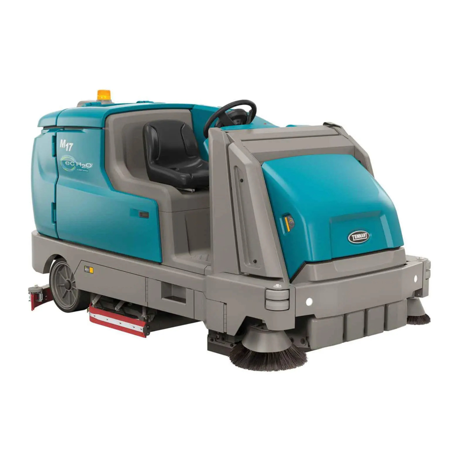
- Page 2 INTENDED USE The M17 is an industrial rider machine designed to wet scrub and sweep both rough and smooth hard surfaces (concrete, tile, stone, synthetic, etc). Typical applications include schools, hospitals / health care facilities, offi ce buildings, and retail centers. Do not use this machine on soil, grass, artifi...
-
Page 3: Table Of Contents
Disengaging The Hopper Support Bar ..58 Help Button ..........32 Draining And Cleaning The Recovery Tank ..59 Video Help Button ........34 Draining And Cleaning The Solution Tank ..62 Completing The Pro-Check Turn Off The Machine ........63 Pre-Operation Checklist ......35 M17 9017351 (12-2019) - Page 4 Lithium-Ion Battery Pack ......89 Skirts And Seals ..........123 Charging The Battery .......90 Sweeping Recirculation Skirts ....123 To Charge With Tennant Branded Charger .. Sweeping Side Skirts ......123 Recovery Tank Seal .......123 To Charge With Enersys Battery Charger 93 Solution Tank Seal .........123 Opportunity Charging (Option) ....95...
- Page 5 Programming The Zone Control Buttons 150 Enabling The Login ........151 Changing The Rear View Camera Settings . Disabling The Login .......152 Disabling / Enabling The Pre-Operation Checklist ..........153 Changing Battery Type ......154 Calibrating The Touch ......155 Checklist Setup ........155 Exporting Checklists .......156 M17 9017351 (12-2019)
- Page 6 CONTENTS M17 9017351 (12-2019)
-
Page 7: Important Safety Instructions - Save These Instructions
CAUTION: To warn of unsafe practices a Tennant representative for information on how to that could result in minor or moderate disable the cellular communication functionality. personal injury. - Page 8 - Do not modify the machine from its original - Follow site safety guidelines concerning wet design. fl oors. - Use Tennant supplied or approved - Do not leave machine unattended when replacement parts. fi lling solution tank with auto-fi ll feature.
- Page 9 - Block machine tires. - Tie machine down to truck or trailer. 7. When using Lithium- ion Battery Model: - Battery service to be performed by Tennant Service only. - Do not attempt to lift battery by hand or by any other unauthorized method.
- Page 10 / step in the lowered position. Do not carry passengers on any pat of the machine. Located on rear bumper door / step. FOR SAFETY LABEL - Authorized Service Mechanic Only. Located on circuit board cover and electrical panel. M17 9017351 (12-2019)
- Page 11 (fl ooded) and sealed AGM batteries. FOR SAFETY LABEL - Read manual before operating machine. WARNING LABEL - Raised hopper may fall. Engage hopper support bar. Located on hopper support bar. Located on electrical panel. M17 9017351 (12-2019)
- Page 12 Wear eye protection. Use hoist when lifting. Hold sprayer with two hands. Located under high pressure washer cover. Located on high pressure washer cover. LITHIUM-ION BATTERY CAUTION LABEL Located on top of battery pack. M17 9017351 (12-2019)
-
Page 13: Operation
X. Recovery tank drain hose K. Rear squeegee Y. Vacuum hose L. Overhead guard (Option) Z. Solution tank drain hose M. Steering wheel AA. High pressure washer (Option) N. Operator seat AB. Live wand dry vacuum (Option) M17 9017351 (12-2019) -
Page 14: Controls And Instruments
B. Directional switch L. Hopper rollout switch C. Emergency shut-off button D. Operating lights / hazard lights switch (Option) E. Spray nozzle switch (Option) / High pressure washer (Option) F. Parking brake pedal G. Brake pedal H. Propel pedal M17 9017351 (12-2019) -
Page 15: Standard Control Panel
J. Main scrub brush pressure button W. Solution decrease button (−) K. Main scrub brush pressure indicator lights X. Solution fl ow indicator lights L. 1−STEP button Y. Solution increase button (+) Z. USB port (Service only) M17 9017351 (12-2019) -
Page 16: Pro-Panel Controls
X. Hopper control button J. Sweeping main brush button Y. USB port (Service only) K. Sweeping vacuum fan button Z. Solution on / off buttons L. Sweeping side brush button M. Rearview camera button N. Solution control access button M17 9017351 (12-2019) -
Page 17: Symbol Defi Nition
Hazard light Spray nozzle (Option) / Sweeping vacuum fan High Pressure washer (Option) Sweeping main brush Severe environment (Option) Scrubbing side brush Circuit breaker Scrubbing vacuum fan / squeegee Jack point Scrubbing main brush Forward / Reverse M17 9017351 (12-2019) - Page 18 Raise hopper Zone setting 2 Lower hopper Zone setting 3 Roll hopper out Battery discharge indicator Roll hopper in Hopper control access Alert / Fault Hour meter Checklist item unconfi rmed Login Checklist item confi rmed Logout Select M17 9017351 (12-2019)
- Page 19 Add / Edit profi les Enable login Operator Calibrate touch Supervisor Checklist setup Edit profi le Export all Add profi le Export new Delete profi le Export checklists Copy profi le Screen lock Enter Date / Time set M17 9017351 (12-2019)
-
Page 20: Operation Of Controls - Standard Panel
HOUR METER The hour meter records the hours the machine was operated. Use this information to determine machine service intervals. M17 9017351 (12-2019) -
Page 21: Contrast Control Button
The indicator light above the button will illuminate when the 1-STEP button is activated. CONFIGURATION MODE BUTTON The confi guration mode button is for accessing the confi guration and diagnostic modes. Only properly trained service personnel and TENNANT representatives should access these modes. M17 9017351 (12-2019) -
Page 22: Sweeping Side Brush Button
Turn off the sweeping vacuum fan: Press the independently from the main scrub brushes. sweeping vacuum fan button. The indicator light The main scrub brushes also come on when the will turn off. scrubbing side brush button is pushed. M17 9017351 (12-2019) -
Page 23: Scrubbing Vacuum Fan / Squeegee Button
SCRUBBING MAIN BRUSH BUTTON Turn on the scrubbing main brush: Press the scrubbing main brush button. The indicator light will illuminate. Turn off the scrubbing main brush: Press the scrubbing main brush button. The indicator light will turn off. M17 9017351 (12-2019) -
Page 24: Severe Environment Switch (Option)
NOTE: The Severe Environment switch can be confi gured to activate longer than fi ve minutes. Contact Tennant service representative. The ec-H2O scrubbing mode is temporarily disabled when the severe environment switch is activated. The ec-H2O mode automatically comes back on when severe environment switch is timed out / turned off. -
Page 25: Operation Of Controls - Pro-Panel
fi rst powered on. Operate the machine a few minutes before reading the charge level of the batteries. NOTE: Machines equipped with the fuel cell option will have the display on the fuel cell pendant. M17 9017351 (12-2019) -
Page 26: Changing The Default Button
The battery status button will once again be the default when the machine is turned on. M17 9017351 (12-2019) -
Page 27: 1-Step Button
The button will turn the standby mode prior to the 1-STEP button being off. pressed. The selected buttons will become fully illuminated when the 1-Step button is pressed. M17 9017351 (12-2019) -
Page 28: Sweeping Side Brush Button
The button will illuminate. Turn off the scrubbing main brush: Press the scrubbing main brush button. The button will turn Turn off the scrubbing side brush: Press the off. scrubbing side brush button. The button will turn off. M17 9017351 (12-2019) -
Page 29: Solution On / Off Button
Press the fi lter shaker button. The fi lter shaker will operate for 30 seconds. The fi lter shaker button will illuminate while the fi lter shaker is operating. Press the fi lter shaker button again if necessary to stop the fi lter shaker. M17 9017351 (12-2019) -
Page 30: Severe Environment Button (Option)
NOTE: The Severe Environment switch can be confi gured to activate longer than fi ve minutes. Contact Tennant service representative. The amount of time remaining for the severe environment scrub is displayed in the middle of the 1-STEP button. It will turn off automatically when the timer expires or when pressed again. -
Page 31: Zone Control Buttons
The rearview camera is located on the recovery tank, above where the vacuum hose is attached to the recovery tank. M17 9017351 (12-2019) -
Page 32: Help Button
Press the back arrow button to return to the main help screen. Press the about button to access machine operating system information. Press the home button to return to the main operating screen. Press the Pre-Operation Checklist button to access the Pre-Operation Checklist. M17 9017351 (12-2019) - Page 33 Press the home button to return to the main operating screen. Press the back arrow button to return to the previous screen. Press the forward arrow button to access machine information from the list. M17 9017351 (12-2019)
-
Page 34: Video Help Button
Press the home button to return to the main operating screen. Press the back arrow button to return to the previous screen. Press the video list button to access a text list of all help videos. M17 9017351 (12-2019) -
Page 35: Completing The Pro-Check Pre-Operation Checklist
Press the video help button to view the video related to a particular checklist item. Press the enter button when ready to start using the machine after completing the checklist. M17 9017351 (12-2019) -
Page 36: Operation Of Controls - All Machines
Only use this button in the event of an emergency. Hazard Lights On: Press the operating / hazard It is not intended for routine machine shutdown. light switch to the middle position. All Lights Off: Press the bottom of the operating / hazard light switch. M17 9017351 (12-2019) -
Page 37: Propel Pedal
PARKING BRAKE PEDAL Position toe onto the parking brake pedal and press both the brake pedal and parking brake pedal down to engage the parking brake. Press just the brake pedal to release the parking brake. M17 9017351 (12-2019) -
Page 38: Rear Bumper Door / Step
NOTE: Step only in the tread area of the rear bumper door / step. Do Not step into the two marked indented non-tread areas on each side of the rear bumper door / step. M17 9017351 (12-2019) -
Page 39: How The Machine Works
fl oor and the vacuum suspended soil. The converted water then returns system draws the dirty solution into the recovery to normal water in the recovery tank. The ec-H2O tank. system can be used while double scrubbing. M17 9017351 (12-2019) -
Page 40: Brush And Pad Information
The spring-activated For best results, use the appropriate brush or centering device works with all Tennant pads and pad for the cleaning application. Listed below are allows for fast, easy pad replacement. -
Page 41: While Operating The Machine
10.5% grade for Dual Force and 5% for Direct Throw. Do not transport on ramp inclines that exceed 13% grade for Dual Force and 5% for Direct Throw (with hopper lowered). M17 9017351 (12-2019) -
Page 42: Pre-Operation Checklist
Check the right side squeegee for wear and damage. Check the solution tank cover seal for wear or damage. ec-H2O Scrubbing: Confi rm all conventional cleaning agents/restorers are drained and rinsed from the solution tank. M17 9017351 (12-2019) -
Page 43: Starting The Machine
4. Place the directional switch into the direction needed to travel. 5. Press the propel pedal to move the machine. NOTE: The machine will not travel unless the operator is sitting in the operator seat. 4. Reinstall the cap onto the detergent tank. M17 9017351 (12-2019) -
Page 44: Filling The Solution Tank
3. Close the solution tank cover. NOTE: Pour a recommended foam control solution into the recovery tank if excessive foam appears. For specifi c detergent recommendations, contact a Tennant representative. 3. Close the solution tank cover. M17 9017351 (12-2019) -
Page 45: Es (Extended Scrub) Mode - Manual Tank Fill
4. Raise the rear bumper door / step. 5. Close the recovery tank cover. 6. Fill the detergent tank with detergent. WARNING: Flammable materials can cause an explosion or fi re. Do not use fl ammable materials in tank(s). M17 9017351 (12-2019) -
Page 46: Ec-H2O Button (Option)
H2O MODULE FLUSH PROCEDURE in the The ec-H2O button will turn red, the fault / alert MAINTENANCE section. indicator button will fl ash, and an ec-H2O error message will appear in the display when there is an ec-H2O error. Standard Panel M17 9017351 (12-2019) -
Page 47: Es (Extended Scrub) Button (Option)
ES button is pushed. Standard Panel Machines equipped with Pro-Panel controls: The slash disappears from the ES button and the button is illuminated when the ES button is pushed to indicate it is active. Pro-Panel M17 9017351 (12-2019) -
Page 48: Scrub Brush Pressure
Use the brush pressure increase (+) button and the brush pressure decrease (-) button to change the brush pressure. The brush pressure indicator bar displays the current brush pressure setting. M17 9017351 (12-2019) -
Page 49: Solution Flow
fl ow indicator lights display the current solution fl ow setting. Use the solution increase (+) button and the solution decrease (-) button to set the solution fl ow level. The solution fl ow indicator bar displays the current solution fl ow setting. M17 9017351 (12-2019) -
Page 50: Scrubbing / Sweeping - Standard Panel
10. Empty the debris hopper and recovery tank at the end of each shift or as needed. See EMPTYING THE HOPPER and DRAINING AND CLEANING THE RECOVERY TANK sections of this manual. M17 9017351 (12-2019) -
Page 51: Scrubbing / Sweeping - Pro-Panel
6. If necessary, activate the scrub mode or zone setting required for the area to be cleaned. 7. Release the parking brake. 11. Release the directional pedal and press the 8. Place the directional switch in the forward brake pedal to stop the machine. position. M17 9017351 (12-2019) -
Page 52: Double Scrubbing
13. Empty the debris hopper and recovery tank squeegees in the raised position. at the end of each shift or as needed. See EMPTYING THE HOPPER and DRAINING AND CLEANING THE RECOVERY TANK sections of this manual. M17 9017351 (12-2019) - Page 53 Pro-Panel Scrub the heavily soiled area. Let the cleaning solution soak on the fl oor for 5-15 minutes. FOR SAFETY: When using machine, go slowly on inclines and slippery surfaces. M17 9017351 (12-2019)
-
Page 54: Water Pickup Mode (No Scrubbing)
Machines equipped with Pro-Panel controls: Press the scrubbing vacuum fan / squeegee button. The button will illuminate, the squeegee will lower, and the vacuum fan will start operating. Pick up the water or non-fl ammable liquid spill. Pro-Panel M17 9017351 (12-2019) -
Page 55: Emptying The Hopper
8. Slowly back the machine away from the debris needed to raise the hopper is 2134 mm (84 in). site or container. 9. Stop the machine, then press and hold the bottom of the hopper raise / lower switch until the hopper is completely lowered. M17 9017351 (12-2019) -
Page 56: Emptying The Hopper - Pro-Panel
7. Press and hold the hopper roll out button to empty the hopper. Release the hopper roll out button when all debris has been emptied from the hopper. 4. Turn off all cleaning functions before raising the hopper. M17 9017351 (12-2019) - Page 57 10. Stop the machine, then press and hold the hopper lower button until the hopper is completely lowered. 11. Press either the home button or the back button to return to the main operating screen. M17 9017351 (12-2019)
-
Page 58: Engaging The Hopper Support Bar
4. Lower and position the hopper support bar onto the support bar stop. WARNING: Lift arm pinch point. Stay clear of hopper lift arms. 4. Completely lower the hopper. WARNING: Raised hopper may fall. Engage hopper support bar. M17 9017351 (12-2019) -
Page 59: Draining And Cleaning The Recovery Tank
4. Hold the drain hose near a fl oor drain, twist the drain nozzle open, and place the hose near the fl oor drain. NOTE: Be sure the drain hose nozzle is pointed in a safe direction before opening the nozzle. M17 9017351 (12-2019) - Page 60 12. Remove the debris tray from the recovery tank and rinse all debris from the tray. 9. Twist the drain cuff closed and insert the drain hose back into the clip on the recovery tank. 13. Close the recovery tank cover. M17 9017351 (12-2019)
- Page 61 NOTE: The scrub head must be lowered approximately 25 mm (1 in) to remove debris trough. NOTE: The debris trough can be removed from the right side of the machine only. 15. Raise the rear bumper door / step. M17 9017351 (12-2019)
-
Page 62: Draining And Cleaning The Solution Tank
fl oor drain. NOTE: Be sure the drain hose nozzle is pointed in a safe direction before opening the nozzle. NOTE: DO NOT use steam to clean the tanks. Excessive heat can damage the tanks and components. M17 9017351 (12-2019) -
Page 63: Turn Off The Machine
8. Twist the drain cuff closed and insert the drain hose back into the clip on the solution tank. 9. Raise the rear bumper door / step. M17 9017351 (12-2019) -
Page 64: Faults / Alerts
Press left arrow button to scroll back through the faults / alerts. Press the home button to return to the main operating screen. Press the back arrow button to return to the previous screen. M17 9017351 (12-2019) -
Page 65: Fault / Alert Indicators
Parking Brake Parking brake engaged Release parking brake 0101 L Scrub Opn Left Scrub Motor Electrical Open Electrical fault Contact qualifi ed Tennant Alert service representative. NOTE: Contact a Tennant Service representative for all other fault codes. M17 9017351 (12-2019) - Page 66 32°F/0°C before operating. If fault code repeats, contact service. 0x0D31 BMS Bus Bar temperature fault Stop operating or charging 0x0D32 machine. Allow battery to cool 0x0D33 down. If fault code repeats, contact service. M17 9017351 (12-2019)
-
Page 67: Options
NOTE: Be sure the spray nozzle switch is turned off before continuing scrubbing. The spray nozzle pump could be damaged if the switch is left on while scrubbing. 3. Open the left shroud to access the spray nozzle. M17 9017351 (12-2019) -
Page 68: High Pressure Washer (Option)
High pressure setting. Twist the nozzle for either the Stream or Fan setting. 3. Unlatch the pressure washer wand tie down and remove the wand from the machine from the machine. 7. Start the machine. M17 9017351 (12-2019) - Page 69 15. Turn off the machine. 16. Disassemble the hose and wand and return them to the proper storage locations. 10. If necessary, adjust the pressure. Turn the knob clockwise to increase pressure and counterclockwise to decrease pressure. M17 9017351 (12-2019)
- Page 70 6. Press the top of the High pressure washer switch to activate the solution pump. The light on the switch will come on when the high pressure washer is turned on. M17 9017351 (12-2019)
-
Page 71: Wet Vacuum Wand (Option)
5. Connect the vacuum wand nozzle to the compartment cover. vacuum wand nozzle hose. 3. Disconnect the vacuum hose from the rear 6. Insert and tighten the vacuum wand handle squeegee. into the vacuum wand nozzle. M17 9017351 (12-2019) - Page 72 17. Lift the rear bumper door / step to the raised position and secure to the rear bumper. 9. Turn on the machine. 10. Press the vacuum fan / squeegee button to turn on the vacuum fan. The squeegee will completely lower. Standard Panel Pro-Panel M17 9017351 (12-2019)
-
Page 73: Live Wand (Option)
3. Operate the machine normally until the live wand is needed. Vacuum dry debris as needed. 4. Turn off live wand switch and return the live wand to storage location when fi nished. M17 9017351 (12-2019) -
Page 74: Emptying The Live Wand Vacuum Debris Tray
1. Unlatch and open the live wand vacuum cover. 5. Replace and latch the live wand vacuum hose. 6. Close and latch the live wand vacuum cover. M17 9017351 (12-2019) -
Page 75: Clean The Live Wand Vacuum Filter
TAPPING - Tap the fi lter, with the dirty side down, gently on a fl at surface. Do not damage the edges of the fi lter. The fi lter will not seal properly in the fi lter frame if the edges of the fi lter are damaged. M17 9017351 (12-2019) -
Page 76: Slide Out Battery (Option)
The machine will not function if the switch is not engaged. 3. Disconnect the battery side cable connector from the machine by pulling down on the connector. Do not pull on the cables. 9. Close the battery compartment side cover and top cover. M17 9017351 (12-2019) -
Page 77: Rear Squeegee Guard (Option)
Increase volume: Turn the knob clockwise. Decrease volume: Turn the knob counter− clockwise. To engage the rear squeegee protector, pull the pin, lower the protector bar, and reinsert the pin. M17 9017351 (12-2019) -
Page 78: Machine Troubleshooting
Clean or replace Poor scrubbing Debris caught on scrub brushes Remove debris from brushes performance Improper detergent / brushes pads Contact Tennant representative for used recommendations Scrub brushes pads worn Replace scrub brushes / pads Excessive brush pressure Reduce scrub brush down pressure... - Page 79 Mineral deposit build-up in module Flush module (See ec-H2O MODULE FLUSH PROCEDURE) Warning and fault indicator light blinking ec-H2O Model: Clogged module Contact Tennant service representative Warning and fault Defective solution pump Replace solution pump indicator light solid red M17 9017351 (12-2019)
- Page 80 Spray nozzle set to low pressure Adjust spray nozzle setting spraying low pressure Spray pump pressure knob turned Adjust the spray pump pressure knob down Poor live wand Clogged hose Remove clog vacuum performance Torn seals on dry vacuum system Replace seals M17 9017351 (12-2019)
-
Page 81: Maintenance
MAINTENANCE MAINTENANCE M17 9017351 (12-2019) - Page 82 Rotate brushes from front to (cylindrical) rear Rotate end for end Main sweeping brushes Rotate brushes from front to Dual Force (cylindrical) rear Rotate end for end Main sweeping brush Rotate end for end Direct Throw (cylindrical) M17 9017351 (12-2019)
- Page 83 Hopper chains Lubricate and check for dam- age and wear. Hopper lift arm pivots Lubricate Scrub vacuum fan Check motor brushes 1 (2) Hours motor(s) Tires Check for damage and wear ■ Check tension. Hopper chains M17 9017351 (12-2019)
- Page 84 Distilled water. Special lubricant, Lubriplate EMB grease (Tennant part number 01433-1) SAE 90 weight gear lubricant HYDO Tennant True premium hydraulic fl uid or equivalent NOTE: More frequent maintenance intervals may be required in extremely dusty conditions. M17 9017351 (12-2019)
-
Page 85: Yellow Touch Points
200 hours. HOPPER CHAINS The hopper chains are located on the left hand side of the machine. Check for damage or wear and lubricate the hopper chains after every 200 hours.. M17 9017351 (12-2019) -
Page 86: Hopper Lift Arm Pivots
500 hours after that. With the hopper in the lowered position; the longer arm chain (A) should not move more than 25 mm (1 in) and the shorter lintel chain (B) should not move more than 12 mm (0.5 in). M17 9017351 (12-2019) -
Page 87: Hydraulics
VI 163 or higher 1057708 19 L (5 gal) If using a locally-available hydraulic fl uid, be sure the specifi cations match Tennant hydraulic fl uid specifi cations. Substitute fl uids can cause premature failure of hydraulic components. ATTENTION! Hydraulic components depend on system hydraulic fl... -
Page 88: Battery
– Allow the charger to completely charge the battery before re using the machine. NOTE: Make sure the battery caps are in place while charging. There may be a sulfur smell after charging batteries. This is normal. M17 9017351 (12-2019) -
Page 89: Maintenance-Free Batteries
When removing or replacing the lithium- ion battery pack, use non-conductive lifting straps positioned at all four lift points with straps angled at 45° or greater when hoisting battery pack. • Contact Tennant Service for lithium-ion battery service and replacement. M17 9017351 (12-2019) -
Page 90: Charging The Battery
4. Plug the charger AC power supply cord into a properly grounded outlet. 5. Disconnect the battery side cable connector from the machine by pulling down on the connector or the battery quick-disconnect lever (option). Do not pull on the cables. M17 9017351 (12-2019) -
Page 91: To Charge With Tennant Branded Charger
MAINTENANCE TO CHARGE WITH TENNANT BRANDED 2. Observe the charger display. CHARGE CHARGER appears on the display when the battery is charging. This is the charger default screen. 1. Turn on the battery charger if required. NNOTE: The Lithium-Ion Battery Pack’s battery management system (BMS) is active for fi... - Page 92 COMPLETE will appear in the display, all the charger status indicators will be illuminated, and the Tennant charger will stop charging when the battery is completely charged. FOR SAFETY: When servicing machine do not disconnect the off-board charger’s DC...
-
Page 93: To Charge With Enersys Battery Charger
The charger will return to the default screen. Refer to manufacture’s operator manual for additional information. 2. Observer the charger display. The charging indicator will illuminate on the display when the battery is charging. This is the charger default screen. M17 9017351 (12-2019) - Page 94 USB port. Do Not plug anything into the USB port while the battery is charging. 11. After the batteries have completely charged, disconnect the charger connector from the battery cable connector. M17 9017351 (12-2019)
-
Page 95: Opportunity Charging (Option)
See CHECKING THE ELECTROLYTE LEVEL. 4. Disconnect the battery side cable connector from the machine by pulling down on the connector. Do not pull on the cables. 6. The battery will be opportunity charged during the break. M17 9017351 (12-2019) -
Page 96: Weekly Equalization Charge (Lead Acid Battery Only)
The default day can be changed to another is operating. Arcing may result. If the charger day if necessary. Consult a Tennant service must be interrupted during charging, press representative about changing the default day. - Page 97 MAINTENANCE The yellow charging indicator will go out and the green charge complete indicator will be illuminated when the battery equalization charge is complete. M17 9017351 (12-2019)
-
Page 98: Battery Watering System (Option)
NOTE: The water supply to the battery water system must always be 7.57 LPM (2 GPM) or more. Use the purger to confi rm the water supply pressure. Refer to manufacturer Operator Manual for additional information. M17 9017351 (12-2019) -
Page 99: Fuel Cell Battery (Option)
MAINTENANCE FUEL CELL BATTERY (OPTION) Machines can be equipped for use with fuel cell battery systems. Contact the fuel cell battery provider for all fuel cell battery information. M17 9017351 (12-2019) -
Page 100: Circuit Breakers, Fuses, And Relays
Strobe light / Flashing light on recovery tank (Option) CB15 Power steering (Option) CB16 Lift module CB17 Sweep module CB18 Sweep vacuum 1 CB19 Sweep vacuum 2 CB20 Not used CB21 2.5A Alarm / Flashing light (Option) M17 9017351 (12-2019) -
Page 101: Fuses
Refer to the table below for the relays and circuits controlled. Relay Rating Circuit Controlled 36 VDC, 200 A Main contactor 36 VDC, 5 A Backup alarm / light (Option) 36 VDC, 100 A Auxiliary line contactor 36 VDC, 200A Sweep contactor M17 9017351 (12-2019) -
Page 102: Hopper Dust Filter / Perma-Filter
1. Remove the hopper cover from the hopper. 5. Clean dust and debris from the dust fi lter tray. 2. Remove the dust fi lter cover. 6. Reinstall the dust fi lter. 7. Reinstall the dust fi lter cover. 8. Reinstall the hopper cover. M17 9017351 (12-2019) -
Page 103: Cleaning The Hopper Dust Filter
If there is a fi re in the hopper, the Thermo-Sentry stops the vacuum fan and cuts off the air fl ow. The Thermo-Sentry automatically resets after cooling down. M17 9017351 (12-2019) -
Page 104: Main Scrub Brushes
REPLACING DISK SCRUB BRUSHES OR PAD DRIVERS 1. Raise the scrub head. 2. Turn off the machine. FOR SAFETY: Before leaving or servicing machine, stop on level surface, turn off machine, set parking brake, and remove key. M17 9017351 (12-2019) -
Page 105: Replacing Disk Scrub Pads
9. Close and secure the squeegee support door driver. and close the main brush access door. 5. Reinstall the pad driver onto the machine. 10. Repeat procedure for the other brushes. M17 9017351 (12-2019) -
Page 106: Cylindrical Scrub Brushes
2. Lift the idler plate retainer handle and unhook 6. If rotating the brushes, always rotate the front the retainer ring from the idler plate hook. with the back so that they wear evenly. They may be rotated end for end as well. Before After M17 9017351 (12-2019) - Page 107 9. Close and secure the squeegee support door and close the main brush access door. 10. Repeat for the brush on the other side of the scrub head. M17 9017351 (12-2019)
-
Page 108: Main Sweep Brushes
6. Slide the brushes into the main sweep brush compartment and all the way onto the drive hubs. 7. Reinstall the main sweep brushes idler plate. 8. Close the main sweeping brush compartment access door. M17 9017351 (12-2019) -
Page 109: Replacing The Direct Throw Main Sweeping Brush (Option)
9. Reinstall the main sweep brush idler plate. 10. Reinstall the idler side skirt and plate. 11. Close the main sweeping brush compartment access door. 12. Lower the hopper. M17 9017351 (12-2019) -
Page 110: Side Brush(Es)
fl oor between 9 o’clock and 2 o’clock when the brushes are in motion. 3. Remove the side brush and retainer from under the side brush assembly. 350327 M17 9017351 (12-2019) -
Page 111: To Adjust Sweeping Side Brush - Standard Panel
The selected side brush will lower and spin. NOTE: Contact a Tennant service representative if there is a fl at pattern (full circle) after the sweeping side brushes have been adjusted. 4. Observe the brush pattern... -
Page 112: To Adjust Sweeping Side Brush - Pro-Panel
9. Recheck the brush patterns. Adjust brush pressure as necessary. NOTE: Contact a Tennant service representative if 4. Press the desired sweeping side brush button there is a fl at pattern (full circle) after the sweeping to adjust it. -
Page 113: Replacing The Scrubbing Side Brush (Option)
6. Place the new side brush underneath the side brush assembly and lift the side brush up onto the side brush hub until the brush locks onto the hub. 7. Reinstall the scrubbing side brush squeegee assembly. M17 9017351 (12-2019) -
Page 114: Squeegee Blades
FOR SAFETY: Before leaving or servicing machine, stop on level surface, turn off machine, set parking brake, and remove key. 2. Disconnect the vacuum hose from the rear squeegee assembly 4. Pull the rear squeegee assembly from the machine. M17 9017351 (12-2019) - Page 115 8. Insert the hinge end of the retainer into the hooks in the rear squeegee assembly. 6. Remove the rear squeegee from the squeegee assembly. M17 9017351 (12-2019)
- Page 116 12. Remove the front squeegee from the squeegee assembly. 10. Turn the rear squeegee assembly over to access the front of the squeegee assembly. M17 9017351 (12-2019)
- Page 117 14. Install the front squeegee retainer onto the rear squeegee assembly. 15. Reinstall the rear squeegee assembly onto the machine 16. Raise the rear bumper door / step if it was lowered to access the rear squeegee assembly. M17 9017351 (12-2019)
-
Page 118: Leveling The Rear Squeegee
5. To adjust the squeegee leveling, loosen the tilt if adjustments were made. lock knob. 9. Readjust the squeegee blade defl ection if necessary. 10. Raise the Rear bumper door / step when fi nished leveling the rear squeegee. M17 9017351 (12-2019) -
Page 119: Adjusting The Rear Squeegee Blade Defl Ection
8. Readjust the squeegee blade defl ection if 3. Lower the rear bumper door / step. necessary. 9. Raise the rear bumper door / step when fi nished adjusting the rear squeegee blade defl ection. M17 9017351 (12-2019) -
Page 120: Replacing Or Rotating The Side Squeegee Blades
4. Remove the retaining band from the side squeegee assembly. 9. Close and secure the squeegee support door and close the main brush access door. 10. Repeat for the side squeegee on the other side of the scrub head. M17 9017351 (12-2019) -
Page 121: Replacing Or Rotating The Scrubbing Side Brush Squeegee Blades (Option)
NOTE: The squeegee blade(s) have slots for adjusting the squeegee blade defl ection. Install / reinstall squeegees so the defl ection is approximately 12 mm (0.50 in) for smooth fl oors and 15 mm (0.62 in) for rough fl oors. M17 9017351 (12-2019) - Page 122 5. Fasten the side brush retaining band latch. spacer, and retaining band onto the side brush assembly. Be sure the holes in the squeegee blade are hooked onto the tabs. 6. Reinstall the side brush squeegee assembly onto the side brush assembly. M17 9017351 (12-2019)
-
Page 123: Skirts And Seals
The side skirts are located on both sides of the main sweeping brushes. The side skirts should be just touching the fl oor. Check the skirts after every 50 hours of operation for damage and wear. Dual Force Sweeping Skirts Direct Throw Sweeping Skirts (Option) M17 9017351 (12-2019) -
Page 124: Scrub Head Skirts (Disk Scrub Heads Only)
Check the hopper dust fi lter cover seal for wear or LIVE WAND VACUUM SEALS (OPTION) damage every 100 hours of operation. Clean dust and debris from the seal as necessary. Check the live wand vacuum seals for damage and wear after every 50 hours of operation. M17 9017351 (12-2019) -
Page 125: Belts
The foot pedal should not travel more than 25 mm (1 in) to engage the brake. Check the brake adjustment after every 200 hours of operation. Direct Throw Sweeping Drive Belt (Option) M17 9017351 (12-2019) -
Page 126: Tires
TRANSPORTING THE MACHINE TIRES FOR SAFETY: When transporting Lithium- ion FOR SAFETY: Before leaving or servicing Battery Model, contact Tennant or your local machine, stop on level surface, turn off regulatory authorities for proper transporting machine, set parking brake, and remove key. - Page 127 7. Lower the hopper, scrub head, and rear squeegee. 8. Connect the tie-down straps to the holes in the rear jacking brackets at the front of the machine. 9. Turn off machine and remove the key after the machine is secured. M17 9017351 (12-2019)
-
Page 128: Machine Jacking
FOR SAFETY: When servicing machine, block machine tires before jacking machine up. Use a hoist or jack that will support the weight of the machine. Jack machine up at designated locations only. Support machine with jack stands. M17 9017351 (12-2019) -
Page 129: Ec-H2O Module Flush Procedure
6. Pour 2 gallons (7.6 liters) of white or rice hose. vinegar into the solution tank. 3. Remove the drain hose from the ec-H2O compartment. M17 9017351 (12-2019) - Page 130 11. Disconnect the drain hose from the ec-H2O manifold hose. 12. Reconnect the outlet hose to the ec-H2O manifold hose. 13. Return the drain hose to storage location in the ec-H2O compartment. 14. Close the right shroud. M17 9017351 (12-2019)
-
Page 131: Storage Information
50°F/10°C~95°F/35°C setting. 1. Completely drain the solution tank, recovery tank, and detergent tank. 2. Pour 7.6 L (2 gal) of Propylene Glycol Based / Recreational Vehicle (RV) antifreeze into the solution tank. Standard Panel Pro-Panel M17 9017351 (12-2019) - Page 132 16. The remaining antifreeze does not need to be drained from the solution tank, recovery tank, 8. Machines with scrubbing side brush option or detergent tank. only: Press the scrubbing side brush button to activate the side brush. Standard Panel Pro-Panel M17 9017351 (12-2019)
-
Page 133: Preparing The Machine For Operation After Storage
4. Machines equipped with optional detergent machine is ready for operation. See PRIMING tank only: Pour 1.9 L (1/2 gal) of cool clean THE ec-H2O SYSTEM for additional instructions. water into the detergent tank. 5. Turn on the machine. M17 9017351 (12-2019) - Page 134 NOTE: Machines equipped with optional ES system will need to drain the antifreeze from the pump lines. 12. Stop the machine. 13. Machines with spray nozzle option only: Operate the wand for a few seconds to clean the antifreeze from the pump. M17 9017351 (12-2019)
-
Page 135: Priming The Ec-H2O System
5. Connect the drain hose to the ec-H2O outlet hose. 2. Open the right shroud to access the ec-H2O assembly. 3. Press the connector button to disconnect the outlet hose from the ec-H2O manifold. 6. Place the drain hose into a empty container. M17 9017351 (12-2019) - Page 136 10. Disconnect the drain hose from the ec-H2O manifold hose. 11. Reconnect the outlet hose to the ec-H2O manifold hose. 12. Place the drain hose back into the ec-H2O compartment. 13. Close the right shroud. M17 9017351 (12-2019)
- Page 137 MAINTENANCE M17 9017351 (12-2019)
-
Page 138: Specifi Cations
Dual force plastic hopper weight capacity 136 Kg (300 lbs) Direct throw steel hopper weight capacity 57 Kg (125 lbs) Hopper minimum ceiling dump height 2134 mm (84 in) Hopper maximum dump height 1525 mm (60 in) M17 9017351 (12-2019) -
Page 139: General Machine Performance
963 kg (2124 lb) 406 mm (15.98 in) W x 930 @ 6 hr rate 988 kg (2178 lb) 963 mm (37.91 in) L x 775 mm (30.51 in) H Lithium-ion Battery 1049 414 kg (914 lb) M17 9017351 (12-2019) -
Page 140: Tires
Up to 3.79 LPM (1.0 GPM) scrubbing side brush) Solution fl ow rate (machines with optional Up to 2.65 LPM (0.70 GMP) - To main scrub head scrubbing side brush) Up to 1.14 LPM (0.30 GPM) - To scrubbing side brush M17 9017351 (12-2019) -
Page 141: High Pressure Washer (Option)
1700 mm (67 in) 2096 mm (82.5 in) 1480 mm (58.25 in) Track Wheel base (at rear wheels) 1163 mm 1041 mm (46 in) (41 in) (S/N 000000-010999) 2850 mm (112.1 in) (S/N 011000- 2865 mm (112.8 in) M17 9017351 (12-2019) -
Page 142: Supervisor Controls
If the new assigned supervisor mode login number is forgotten, please contact Tennant service. Press the backspace button if necessary to delete and reenter a number. -
Page 143: Entering The Supervisor Mode
Press the backspace button if necessary to delete and reenter a number. 3. The supervisor machine operation screen should appear in the display. Press the settings button to access the supervisor settings screen. M17 9017351 (12-2019) -
Page 144: Supervisor Setting Screen / Screen Icons
Press the down arrow button to navigate down through the menu items. Press the home button to navigate back to the main operating screen. Press the back button to navigate back to the previous screen. M17 9017351 (12-2019) -
Page 145: Setting / Changing The Screen Lock
SETTING THE SCREEN LOCK. Press the up arrow button to scroll up through screen lock times. 3. Press the home button when fi nished setting / changing the screen lock time to return to the main operating screen. M17 9017351 (12-2019) -
Page 146: Adding / Editing Profi Les
Press the Delete Profi le button to delete an existing profi le. Press the home button to navigate back to the main operating screen. Press the back button to navigate back to the previous screen. M17 9017351 (12-2019) -
Page 147: Setting / Changing The Date And Time
5. Use the keypad to enter the new user / to access the supervisor settings screen. See supervisor name. Press the enter button. ENTERING THE SUPERVISOR MODE. 2. Press the System Time button to access the date / time screen. M17 9017351 (12-2019) - Page 148 Press the km/h button to set the machine speed to kilometers per hour. Press the enter button to set the maximum speed for the machine. M17 9017351 (12-2019)
- Page 149 9. The new user profi le is now saved to the operator profi le list. Multiple operator and supervisor user profi les can be added. Press the back arrow button to return to the previous screen to add more user profi les or to enable login. M17 9017351 (12-2019)
-
Page 150: Programming The Zone Control Buttons
Turning the key to the off position is another way to also logout. 13. Use the Edit Profi le button, Copy Profi le button, and Delete Profi le button to manage the current user profi les. M17 9017351 (12-2019) -
Page 151: Enabling The Login
Press the home button to navigate back to the main operating screen. Press the back button to navigate back to the previous screen. M17 9017351 (12-2019) -
Page 152: Disabling The Login
Press the home button to navigate back to the main operating screen. Press the back button to navigate back to the previous screen. 4. Press either the Operator button or Supervisor button to select the desired default user. M17 9017351 (12-2019) -
Page 153: Disabling / Enabling The Pre-Operation
ENTERING THE SUPERVISOR MODE. 2. Press the Checklist Setup button to access the 6. At start up, the home screen is now set without Pre-Operation Checklist setup screen. a login requirement for the operator profi le as the default. M17 9017351 (12-2019) -
Page 154: Changing Battery Type
Pre-Operation Checklist. A check mark appears in the chosen interval. Press the home button to navigate back to the main operating screen. Press the back button to navigate back to the previous screen. M17 9017351 (12-2019) -
Page 155: Calibrating The Touch
See ENTERING THE SUPERVISOR MODE. 2. Press the Calibrate Touch button to recalibrate touch. If the touch points become misaligned. Press the down arrow button to scroll down through Pre-Operation Checklist items. M17 9017351 (12-2019) -
Page 156: Exporting Checklists
Press the home button to navigate back to the export screen. the main operating screen. Press the back button to navigate back to the previous screen. 5. Remove the fl ash drive from USB port and turn off the machine. M17 9017351 (12-2019)
Need help?
Do you have a question about the M17 and is the answer not in the manual?
Questions and answers