Table of Contents
Advertisement
Quick Links
PCIe-FRM22
User Manual
Version 1.1
ⓒ 2005 DAQ SYSTEM Co., Ltd. All rights reserved.
Microsoft® is a registered trademark; Windows®, Windows NT®, Windows XP®, Windows 7®, Windows 8®, Windows 10®
All other trademarks or intellectual property mentioned herein belongs to their respective owners.
Information furnished by DAQ SYSTEM is believed to be accurate and reliable, However, no responsibility is assumed by DAQ SYSTEM for its use, nor
for any infringements of patents or other rights of third parties which may result from its use. No license is granted by implication or otherwise under
any patent or copyrights of DAQ SYSTEM.
The information in this document is subject to change without notice and no part of this document may be copied or reproduced without the prior
written consent.
Advertisement
Table of Contents

Related Manuals for DAQ system PCIe-FRM22


Summary of Contents for DAQ system PCIe-FRM22
- Page 1 All other trademarks or intellectual property mentioned herein belongs to their respective owners. Information furnished by DAQ SYSTEM is believed to be accurate and reliable, However, no responsibility is assumed by DAQ SYSTEM for its use, nor for any infringements of patents or other rights of third parties which may result from its use. No license is granted by implication or otherwise under any patent or copyrights of DAQ SYSTEM.
-
Page 2: Table Of Contents
PCIe-FRM22 User’s Manual Contents 1. Introduction -------------------------------------------------------------------------- 1-1 Product Features ------------------------------------------------------------------------- 1-2 Product Application ------------------------------------------------------------------------- 2. PCIe-FRM22 Board Function ----------------------------------------------------- 3. PCIe-FRM22 Board Description 3-1 PCIe-FRM22 Board Layout ----------------------------------------------------------------- 3-2 Device Features ------------------------------------------------------------------- 3-3 Connector Pin out 3-3-1 RGB(DSUB-15) Connector... -
Page 3: Introduction
Player [Figure 1-1. PCIe-FRM22 Board Usage] [Figure 1-1] shows an example of using the PCIe-FRM22 board. The PCIe-FRM22 board is connected to the PCI Express slot of the right PC, and the screens of various devices on the left can be transmitted to the RGB, HDMI or DVI ports. -
Page 4: Product Features
PCIe-FRM22 User’s Manual 1-1 제품 사양 Items Description Remark Hardware PC Interface PCI Express x1 Operation Power PC Power +3.3V (Max 1.1A) +12V (Max 1A). Video Interface Supports 525p, 625p component DVI (Digital Video Interface) 1.0 progressive scan formats HDMI 1.3... -
Page 5: Product Application
PCIe-FRM22 User’s Manual 1-2 Product Applications Image recognition (Pattern, particle, etc.) Inspection equipment (Sensor, Semiconductor, Device etc.) Security Solution Medical Image Capture BLU-RAY Game Consoles ... -
Page 6: Pcie-Frm22 Board Function
PCIe-FRM22 User’s Manual 2. PCIe-FRM22 Board Function In the case of PCIe-FRM22, FPGA Core Logic is in charge of overall control. It receives RGB, HDMI (High-Definition Multimedia Interface), and DVI (Digital Visual Interface) signals as its main function and delivers it to the PC. -
Page 7: Pcie-Frm22 Board Description
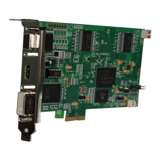
PCIe-FRM22 User’s Manual 3. PCIe-FRM22 Board Description Each important board function is briefly described. For detailed function information, please refer to the parts specification. 3-1 PCIe-FRM22 Board Layout [Figure 3-1. PCIe-FRM22 Layout] There are seven LEDs on the board, and the description of each is as follows. -
Page 8: Device Features
PCIe-FRM22 User’s Manual 3-2 Device Features (1) FPGA : U7 All of the board functions are controlled by the Logic program of the FPGA. (2) Video Receiver : U3 Receives RGB, HDMI, and DVI data and transmits it to FPGA. -
Page 9: Connector Pin Out
PCIe-FRM22 User’s Manual 3-3 Connector Pin-out The connectors and jumpers used in PCIe-FRM22 will be described. The main connectors are HDMI connector CON1 for HDMI connection, DVI connector CON2 for DVI connection, and DSUB15Pin-Dip connector P1 for RGB connection. 3-3-1 RGB(DSUB-15) Connector The DSUB-15 PIN DIP connector is an RGB signal connector and the pin map is as shown below. -
Page 10: Hdmi Connector
PCIe-FRM22 User’s Manual DDC_DATA I2C Data HS_IN Horizontal Sync VS_IN Vertical Sync DDC_CLK I2C Clock 3-3-2 HDMI Connector The HDMI connector is an HDMI signal connector, and the pin map is as shown below. [Figure 3-3. HDMI pin-out] [Table 2. HDMI Connector CON1] Pin No. -
Page 11: Dvi Connector
[Figure 3-4] below shows the pin map of the DVI connector on the board. All pin specifications are input/output based on the DVI standard, so please refer to the DVI standard document for details. [Figure 3-4. PCIe-FRM22 CN2 Connector Pin-out] [Table 3. CN2 DVI Connector] Pin #... -
Page 12: J1 Connector
Analog Horizontal Sync (Disabled) Analog Ground R, G, B signal regression (Disabled) 3-3-4 J1 Connector On the PCIe-FRM22 board, 4 digital inputs and 4 digital outputs isolated by photo-couplers can be used through the J1 connector. The circuit is as follows. 3.3V 2.4K DIN[3..0]... - Page 13 PCIe-FRM22 User’s Manual The output uses a 22 ohm resistor to limit the maximum output current. Output current should be used within 10mA. In special circumstances, the R value is adjusted and used to operate according to the above description. The pin map of the connector is shown in the figure below.
-
Page 14: J4 Connector
3-3-7 SW1 Switch The PCIe-FRM22 board is designed so that up to four PCIe-FRM22 boards can be used simultaneously in one system (PC). Each board classification can be set through the 4-pin DIP switch (SW1) in the board. -
Page 15: Installation
PCIe-FRM22 User’s Manual 4. Installation 4-1 Product Contents Before installing the board, check that the contents of the package are intact. 1. PCIe-FRM21 Board 2. CD (Drivers/Manual/API/Sample source etc.) Document Folder : Manual and Catalog Driver Folder : pcie_frm22.sys pcie-frm22.inf... -
Page 16: Installation Process
The board environment must be Windows 2000 SP4 or higher and Windows XP SP1 or higher. First, turn off the PC's power, plug the PCIe-FRM22 board into the PCI Express Slot, and turn on the PC's power. When the “Start New Hardware Wizard” window opens as shown below, select as shown below and click the Next button. - Page 17 PCIe-FRM22 User’s Manual 2. Select Driver from the enclosed CD and click the Next button. 3. Click the Next button. It indicates that the installation process is proceeding as shown below. The driver folder contains “pcie_frm22.inf” and “pcie_frm22.sys” files required for driver...
- Page 18 4. When the installation is completed normally, it is shown in the figure below. When the installation is complete, check whether the driver is installed normally in the following way. 6. In My Computer -> Properties -> Hardware -> Device Manager, check if the Multifunction Adapter -> “PCIe-FRM22” is installed.
- Page 19 PCIe-FRM22 User’s Manual 7. If it appears as shown in the figure below, the installation has been completed normally. If you can see the “PCIe-FRM22” at Multifunction Adaptors, the driver installation is to have been over. Notice : After installation, you should re-boot the system for the proper operation.
-
Page 20: Sample Program
PCIe-FRM22 User’s Manual 5. Sample Program In the Exe folder of the CDROM provided with the board, a sample program “FrmTest.exe” is provided for easy use of the board. By displaying Frame Data as hexadecimal values, it is stored in memory or hard disk so that developers can utilize the frame data needed. - Page 21 PCIe-FRM22 User’s Manual The description of each menu bar is as follows. The menu bar not described here is an unused function. (1) “Resolution” button User can set up the resolution (640x480, 800x600, 1024x768, 1280x720, 1280x1024, 1600x1200, 1920x1080, 1920x1200, 2048xx1536, 2560x2048, 1600x1200RGB, 1920x1200RGB).
- Page 22 PCIe-FRM22 User’s Manual (12) “Auto View” click When check this box, it displays a video. (13) “I2C Init” button It used to save Video Input Mode as below “Input Select” . (14) “Input Select” It selects a Video Input Mode.
-
Page 23: Appendix
PCIe-FRM22 User’s Manual Appendix Board Size The external sizes of the board are as follows. For detailed dimensions, please contact the person in charge. -
Page 24: Repair Regulations
⑥ Products whose serial number has been changed or removed intentionally ⑦ If DAQ SYSTEM determines that it is the customer's fault for other reasons (5) Shipping costs for returning the repaired product to DAQ SYSTEM are the responsibility of the customer. -
Page 25: References
1. PCI Local Bus Specification Revision2.1 -- PCI Special Interest Group 2. How to install PCI DAQ Board -- DAQ system 3. AN201 How to build application using API -- DAQ system 4. AN312 PCIe-FRM22 API Programming -- DAQ system... - Page 26 PCIe-FRM22 User’s Manual MEMO Contact Point Web sit : https://www.daqsystem.com Email : postmaster@daqsystem.com...
Need help?
Do you have a question about the PCIe-FRM22 and is the answer not in the manual?
Questions and answers