Table of Contents
Advertisement
Quick Links
PCIe-DIO6400
User Manual
Version 1.0
ⓒ 2005 DAQ SYSTEM Co., Ltd. All rights reserved.
Microsoft® is a registered trademark; Windows®, Windows NT®, Windows XP®, Windows 7®, Windows 8®, Windows 10®
All other trademarks or intellectual property mentioned herein belongs to their respective owners.
Information furnished by DAQ SYSTEM is believed to be accurate and reliable, However, no responsibility is assumed by DAQ SYSTEM for its use, nor
for any infringements of patents or other rights of third parties which may result from its use. No license is granted by implication or otherwise under
any patent or copyrights of DAQ SYSTEM.
The information in this document is subject to change without notice and no part of this document may be copied or reproduced without the prior
written consent.
Advertisement
Table of Contents

Related Manuals for DAQ system PCIe-D106400


Summary of Contents for DAQ system PCIe-D106400
- Page 1 All other trademarks or intellectual property mentioned herein belongs to their respective owners. Information furnished by DAQ SYSTEM is believed to be accurate and reliable, However, no responsibility is assumed by DAQ SYSTEM for its use, nor for any infringements of patents or other rights of third parties which may result from its use. No license is granted by implication or otherwise under any patent or copyrights of DAQ SYSTEM.
-
Page 2: Table Of Contents
PCIe-DIO6400 User‟s Manual Contents 1. PCI-DIO6400 Block Diagram -------------------------------------------------------- 2. Connector Pin Map ------------------------------------------------------------- 3. Digital Input Circuit ------------------------------------------------------------- 4. Digital Output Circuit ------------------------------------------------------------- 5. External Connection (INPUT) ---------------------------------------------------- 6. External Connection (OUTPUT) ---------------------------------------------------- 7. Internal Power Option Setup 7-1 Power Option Setup ----------------------------------------------------------------------- 7-2 Board Address Setup -----------------------------------------------------------------------... - Page 3 PCIe-DIO6400 User‟s Manual 9. Sample Program 9-1 Program Interface ---------------------------------------------------------------------- 9-2 Function Description ---------------------------------------------------------------------- Appendix A-1 Repair Regulations ----------------------------------------------------------------------- Reference -----------------------------------------------------------------------...
-
Page 4: Pci-Dio6400 Block Diagram
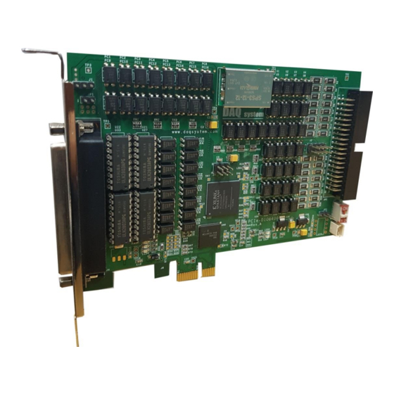
PCIe-DIO6400 User‟s Manual 1. PCIe-DIO6400 Block Diagram PCIe-DIO6400 INTERNAL BLOCK Express PCI External Interface Local Bus Address Data(Mem,I/O) PCI Target 32bit Output BUS Mux MEM Decoder To each IO Module IO Decoder 32bit Input [Figure 1-1. PCIe-DIO6400 Internal Block Diagram] The PCIe-DIO6400 is designed for high performance digital logger with Express PCI x1 Interface. - Page 5 PCIe-DIO6400 User‟s Manual [Figure 1-2. PCIe-DIO6400 Bracket & Board Layout] The 37-pin D-SUB connector (J4) fixed to the standard PCI Express Bracket is used to connect an external interface for digital output, and the digital input is a 40-pin (20x2, 2.54mm pitch) right- angle header connector on the PCB ( JP2).
- Page 6 PCIe-DIO6400 User‟s Manual 1-1 Product Features Items Description Remark Hardware PC Interface PCI Express x1 32bit/33Mhz Operation Power +5VDC(±5%) at 250mA typical I/O Port D-Sub37 Boards PCIe-DIO6400 32/32bit Digital I/O Isolated Digital Input Maximum Input Range(Non-polarity) : 24V Digital Logic Levels : Input High level 5 ~24V Input Low voltage 0 ~ 1.5V Input Resistance : 2.4Kohm@0.5W Isolation Voltage : 5000Vrms...
- Page 7 PCIe-DIO6400 User‟s Manual DAQ System Digital I/O Products Product No. In/Out Timer/Counter Specification cPCI-DIO6400 32/32 Isolated Input/Output 128 channels Software cPCI-DIO02 Read/Write in 8 Groups in 16-bit Units Configurable PCI(e)-DIO6400 32/32 Isolated Input/Output PCI-DIO6401 64/None Isolated Input PCI-DIO6402 None/64...
-
Page 8: Connector Pin Map
PCIe-DIO6400 User‟s Manual 2. Connector Pin Map The PCIe-DIO6400 board is equipped with 37 pin D-SUB connector for external digital output in standard Express PCI Bracket. [Figure 2-1] shows the bracket and connector of the board. POWER DOUT31 DOUT30 DOUT29 DOUT28 DOUT27 DOUT26... - Page 9 PCIe-DIO6400 User‟s Manual DOUT6 Isolated Digital Output 6 DOUT8 Isolated Digital Output 8 DOUT10 Isolated Digital Output 10 DOUT12 Isolated Digital Output 12 DOUT14 Isolated Digital Output 14 GROUND External Ground GROUND External Ground DOUT16 Isolated Digital Output 16 DOUT18 Isolated Digital Output 18 DOUT20 Isolated Digital Output 20...
- Page 10 PCIe-DIO6400 User‟s Manual It is used to a header (JP2) of 40 pin (20x2, 2.54mm Pitch) Right-angle for external digital input. DIN0 DIN1 DIN2 DIN3 DIN4 DIN5 DIN6 DIN7 DIN8 DIN9 DIN10 DIN11 DIN12 DIN13 DIN14 DIN15 IN_COM0 IN_COM1 IN_COM2 IN_COM3 DIN16 DIN17...
- Page 11 PCIe-DIO6400 User‟s Manual DIN6 Isolated Digital Input 6 DIN7 Isolated Digital Input 7 DIN8 Isolated Digital Input 8 DIN9 Isolated Digital Input 9 DIN10 Isolated Digital Input 10 DIN11 Isolated Digital Input 11 DIN12 Isolated Digital Input 12 DIN13 Isolated Digital Input 13 DIN14 Isolated Digital Input 14 DIN15...
-
Page 12: Digital Input Circuit
PCIe-DIO6400 User‟s Manual 3. Digital Input Circuit IN_COM0 2.4K DIN0 2.4K DIN1 2.4K DIN7 [Figure 3-1. Digital Input Circuit] In the figure above, the digital input circuit is insulated by a port coupler. If a positive voltage is applied to “IN_COM0” and a negative voltage is applied to the digital input, current flows through the diode inside as a photo coupler, and the output transistor is energized according to the flowing current. - Page 13 PCIe-DIO6400 User‟s Manual For input, a 40-pin (20x2, 2.54mm pitch) right-angle header connector on the board and a 37-pin terminal board are connected, so a 40-pin to 37-pin connection cable is required as shown in the figure below. The figure below shows the ACC-DSUB37_TB01 terminal board connected to the end of the 37pin cable.
-
Page 14: Digital Output Circuit
PCIe-DIO6400 User‟s Manual 4. Digital Output Circuit OUT_POWER OUT_VDD +3.3V DOUT0 out0 DOUT1 out1 DOUT31 out31 [Figure 4-1. Digital Output Circuit] In [Figure 4-1], the digital output circuit is insulated by a port coupler. “OUT_POWER” and “OUT_VDD” are commonly connected to the output circuit. “OUT_POWER” becomes 12V PCI or ISO 12V (DC-DC output power) inside the board according to the jumper setting of connector J1. -
Page 15: External Connection (Input)
PCIe-DIO6400 User‟s Manual 5. External Connection (INPUT) IN_COM0~3 POWER Signal Input [Figure 5-1. Input Port External Connection] When industrial equipment is connected and operated, noise and common ground problems can usually occur. As a way to solve this problem, an electrically insulated connection method is used. The use of a photo coupler is a good example. -
Page 16: External Connection (Output)
PCIe-DIO6400 User‟s Manual 6. External Connection (OUTPUT) PCIe-DIO6400 Board J1 Jumper External DC-DC+12V Connection Power OUT_POWER PCI +12V Power OUT_VDD LOAD +3.3V DOUT 31 - 0 OUT31-0 External GROUND GROUND [Figure 6-1. Output Port External Connection] OUTPUT can be used by selecting external power or internal power. As shown in [Figure 9], when using an external power source, the J1 jumper must not be connected for complete isolated output. - Page 17 PCIe-DIO6400 User‟s Manual OUT_POWER OUT_VDD POWER OUT 31-0 GROUND [Figure 6-2. External Connection] [Figure 6-2] shows the output port connection through the 37-pin D-sub connector.
-
Page 18: Internal Power Option Setup
PCIe-DIO6400 User‟s Manual 7. Internal Power Option Setup DC-DC_12V Converter POWER GROUND [Figure 7-1. PCIe-DIO6400 Appearance] 7-1 Power Option Setup If usable environment don‟t use external power, it can use at boards which it supplied the power. At this time it can set up by jumper whether or not output to power of isolated DC-DC_12V Converter (option) or output to power of PC Internal Power (+5V). -
Page 19: Board Address Setup
PCIe-DIO6400 User‟s Manual Also the GROUND can select whether or not output to DC-DC Converter (option) GROUND or output to internal PC GROUND. If it uses PC internal power, it shall certainly set up to PC GROUND. JP1 Jumper PC GROUND * The basic option doesn’t work to set up a jumper setting in case of shipment. -
Page 20: Installation
PCIe-DIO6400 User‟s Manual 8. Installation Before installing the board, check that the contents of the package are intact. 8-1 Hardware Installation 8-1-1 Product Contents 1. PCIe-DIO6400 Board 2. CD (Driver/Manual/API/Sample Source etc.) 8-1-2 Installation Process ① Turn off the computer. ②... -
Page 21: Driver Installation
PCIe-DIO6400 User‟s Manual 8-2 Driver Installation After installing the board, install the driver and sample application to run the board on your PC. For installation, use the supplied CD. The installation procedure is as follows, and unless otherwise specified, it is explained based on Windows XP. - Page 22 PCIe-DIO6400 User‟s Manual (3) When you click Next, the driver files are installed. (4) When the installation is complete, normally same as the picture below.
- Page 23 PCIe-DIO6400 User‟s Manual (5) If the installation is completely finished, you confirm it in the following ways. Do the following steps to show up the “Device Manager” window. [My Computer -> properties -> Hardware -> Device Manager -> Multifunction Adaptors -> PCI-DIO6400] If you can see the “PCI-DIO6400”...
-
Page 24: Sample Program
9-1 Program Interface DAQ system provides a sample program to make the user be familiar with the board operation and to make the program development easier. You can find the sample program in the CDROM accompanying with the board. -
Page 25: Function Description
PCIe-DIO6400 User‟s Manual 9-2 Function Description (1) „Model No‟ Button Select the model name PCI-DIO6400. (2) „Board No‟ Button Select the selected board number (Board #0 ~ Board #3) when clicked. The board number is set to SW1 in the board and up to 4 units can be connected. (3) „Open Device‟... -
Page 26: Appendix
(3) All DAQ SYSTEM products have a one-year warranty. -. The warranty period is counted from the date the product is shipped from DAQ SYSTEM. -. Peripherals and third-party products not manufactured by DAQ SYSTEM are covered by the manufacturer's warranty. - Page 27 PCIe-DIO6400 User‟s Manual References 1. PCI System Architecture -- MindShare Inc. 2. PCI Local Bus Specification -- PCI-SIG 3. AN201 How to build application using APIs -- DAQ system 4. AN242 PCI-DIO64xx Series API Programming -- DAQ system...
- Page 28 PCIe-DIO6400 User‟s Manual MEMO Contact Point Web sit : https://www.daqsystem.com Email : postmaster@daqsystem.com...
Need help?
Do you have a question about the PCIe-D106400 and is the answer not in the manual?
Questions and answers