
Subscribe to Our Youtube Channel
Related Manuals for Holman 48301TC


Summary of Contents for Holman 48301TC
- Page 1 Instruction Guide 48301TC Holman Rancho Cordova, CA 95742 800-343-7486 InstallationSupport@Holman.com 20220606R1 DATE: _____________...
-
Page 2: Table Of Contents
Step 7 – Square and Tighten .................. 11 Before You Begin Read all instructions prior to installing any Holman product. These instructions provide NO DRILL mounting for a 32” wide shelf unit. These instructions show the shelf unit installed on the passenger side of vehicle. -
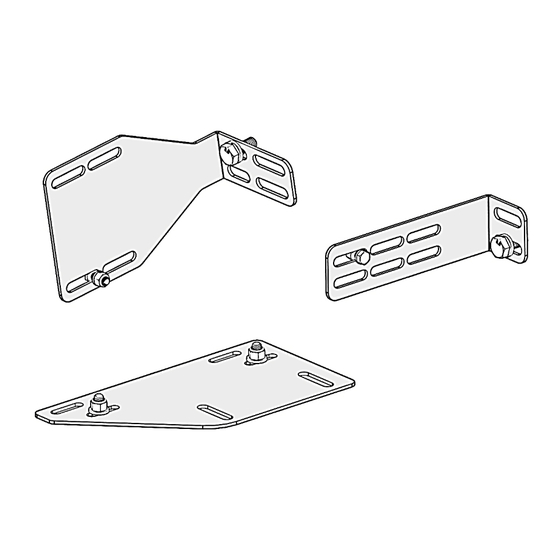
Page 3: Parts
Instructions – 48301TC Parts Hardware For Technical Support Call: 800-343-7486, Monday-Friday, 7AM - 4 PM (PST) Page 3... -
Page 4: Step 1 - Locate Rear Mount Locations
Instructions – 48301TC Step 1 – Locate Rear Mount Locations Find the threaded embosses at the rear of the slider door as shown below. For Technical Support Call: 800-343-7486, Monday-Friday, 7AM - 4 PM (PST) Page 4... -
Page 5: Step 2 - Mount Small Wall Mount
Instructions – 48301TC Step 2 – Mount Small Wall Mount Mount the small wall mount at the threaded emboss near the rear doors. Bolt through the slot shown on the small wall mount using a M10 x 25mm hex head, M10 lock washer, and M10 flat washer. -
Page 6: Step 3 - Mount Large Wall Mount
Instructions – 48301TC Step 3 – Mount Large Wall Mount Mount the large wall mount to the threaded emboss directly behind the slider door. Bolt through the slot shown on the large wall mount using a M10 x 25mm hex head, M10 lock washer, and M10 flat washer. -
Page 7: Step 4 - Mount Base Plate
Instructions – 48301TC Step 4 – Mount Base Plate Locate the “D-Ring” at the rear of the slider door opening as shown below and remove. For Technical Support Call: 800-343-7486, Monday-Friday, 7AM - 4 PM (PST) Page 7... - Page 8 Instructions – 48301TC Place the base plate over the threaded emboss where the “D-Ring” was previously removed, in the orientation shown. Use the slot on the base plate as shown. Place the nylon spacer from the shelf mount kit under the base plate and aligned with the threaded emboss.
-
Page 9: Step 5 - Mount Shelf To Base Plate
Instructions – 48301TC Step 5 – Mount Shelf to Base Plate Place shelf on top of the carriage bolts protruding through the base plate. Note: be sure the top of the shelf is in between the two previously installed wall mounts ... -
Page 10: Step 6 - Mount Shelf To Wall Mounts
Instructions – 48301TC Step 6 – Mount Shelf to Wall Mounts Using 1/4" x 3/4” hex head bolts, 1/4" flat washers and 1/4" lock nuts, attach the shelf to both wall mounts using the hardware from the shelf mount kit, in the order shown. -
Page 11: Step 7 - Square And Tighten
Instructions – 48301TC Step 7 – Square and Tighten Align and square the shelf unit to your liking. Tighten ALL hardware starting from the top and working downwards. Passenger side mounting Shelf can be mounted on the drivers’ side of vehicle as well.
Need help?
Do you have a question about the 48301TC and is the answer not in the manual?
Questions and answers