Table of Contents
Advertisement
Quick Links
© Panduit Corp. 2023
WME3BL, WME6BL, & WME9BL
List of Components:
(1) Pair of Horizontal active E-rails
(1) Pair of Passive E-rails
(4) #12-24 screws
(4) M5 thread forming bonding screws
(1) Roll of T
(2) Keys
(1) Roll of grommet edging
MAXIMUM LOAD RATING.
WME3BL - 200 LB [91 kG]
WME6BL - 300 LB [136 kG]
WME9BL - 400 LB [181 kG]
INSTALLATION INSTRUCTIONS
hook & loop cable tie
-T
AK
Y
TABLE OF CONTENTS
Enclosure dimensions and accessories.........................................2
Explanation of Enclosure components..........................................3
Mounting Enclosure and Electrical box installation........................4-5
Door and Handle reversal...........................................................6
Grounding...............................................................................7
Termination of backbone cable....................................................8
PZAEFAN Fan kit installation......................................................8
Switch configuration..............................................................9-10
Server & Switch configuration................................................11-12
Max capacity Server configuration..........................................13-14
Filter cover installation..............................................................15
WMEBR Brushed Entry kit installation..........................................16
For Technical Support: www.panduit.com
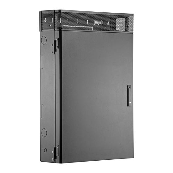
Vertical Wall Mount Enclosure
Part Numbers: WME3BL, WME6BL, WME9BL
Page 1 of 16
V00029TB_04
Advertisement
Table of Contents

Subscribe to Our Youtube Channel
Related Manuals for Panduit WME3BL


Summary of Contents for Panduit WME3BL
-
Page 1: Table Of Contents
& loop cable tie (2) Keys (1) Roll of grommet edging MAXIMUM LOAD RATING. WME3BL - 200 LB [91 kG] WME6BL - 300 LB [136 kG] WME9BL - 400 LB [181 kG] TABLE OF CONTENTS Enclosure dimensions and accessories…………………………………..2 Explanation of Enclosure components……………………………………3... -
Page 2: Enclosure Dimensions And Accessories
INSTALLATION INSTRUCTIONS INSTALLATION INSTRUCTIONS V00029TB_04 © Panduit Corp. 2023 28.5” ENCLOSURE DEPTH [724mm] WME3* 9.5" [240mm] WME6* 14.7" [374mm] WME9* 19.9" [506mm] 42.0” [1068mm] PZAEGK Equipment Grounding Bracket Kit Optional Accessories PZAEFAN Fan Kit WME0UB WMEBR WME*1RU Zero RU Bracket... -
Page 3: Explanation Of Enclosure Components
INSTALLATION INSTRUCTIONS INSTALLATION INSTRUCTIONS V00029TB_04 © Panduit Corp. 2023 Removable Top Lid Perforated for airflow Combination 1/2" or 3/4" T70 Raceway knock-out knock-out (2 plcs. top & bottom) (top & bottom) Combination 1" or 1 1/4" knock-outs (6 plcs. top & bottom) -
Page 4: Mounting Enclosure And Electrical Box Installation
3. Locate the wall studs (16" on center in most U.S. cases). 4. PANDUIT recommends mounting the top of the enclosure at 6’ from the floor (See View 1). Ensure at least 4" clearance on left and right sides of enclosure and 10"... - Page 5 INSTALLATION INSTRUCTIONS INSTALLATION INSTRUCTIONS V00029TB_04 © Panduit Corp. 2023 6. Determine if you will be mounting the electrical box in the wall or inside the enclosure. If Mounting Electrical Box in the Wall: Remove desired breakout from back of enclosure. Deter- mine location for mounting electrical box in wall.
-
Page 6: Door And Handle Reversal
INSTALLATION INSTRUCTIONS INSTALLATION INSTRUCTIONS V00029TB_04 © Panduit Corp. 2023 Reversing Door and Handle Remove door by opening to 90°, and lifting up over the hinge pins. Remove the hinge pins. Remove hinges using a 7/16" wrench/ratchet to loosen the nuts. Remove nuts, washers, &... -
Page 7: Grounding
INSTALLATION INSTRUCTIONS INSTALLATION INSTRUCTIONS V00029TB_04 © Panduit Corp. 2023 Grounding Run grounding cable (GJS6120U or similar, sold separately) from Tele- communications Grounding Busbar (TGB) or conduit ground conductor to enclosure and attach to the specified M6 grounding stud on the enclo- sure base. -
Page 8: Termination Of Backbone Cable
2 Once cable is inside the enclosure, terminate the cable to the appropriate module (fiber or copper). 3 Place module(s) in a M Six Position Multi- Media Surface Mount Box (PANDUIT Part No. Backbone CBXF6IW-AY, sold separately). Mount the box to cable the back wall of the enclosure using supplied adhesive tape. -
Page 9: Switch Configuration
Remove conduit KO plates for maximum cable capacity. 3. Install patch panels (suggested PANDUIT Part No. CPPL24WBL sold separately) to the Passive E-rails from the bottom side. (See figure 5.2) 4. Secure cables to back wall using supplied T (See figure 5.4). - Page 10 Patch Cord Installation 1. Connect horizontal cabling to active network equipment with patch cords (sold separately). PANDUIT recommends using 5 ft. patch cords. 2. Connect patch cords starting from the outside of the patch panel working your way towards the middle.
-
Page 11: Server & Switch Configuration
INSTALLATION INSTRUCTIONS INSTALLATION INSTRUCTIONS V00029TB_04 © Panduit Corp. 2023 Server & Switch configuration Set E-rails to maximum height for server mounting Set additional E-rails (WME*1RU sold separately) at a lower position Set additional E-rails (WME*1RU sold separately) at the lowest position for... - Page 12 INSTALLATION INSTRUCTIONS INSTALLATION INSTRUCTIONS V00029TB_04 © Panduit Corp. 2023 Equipment Installation (cont.) 4. Mount Switch on the middle E-rails in the next available RU. 5. Mount patch panels to the zero RU brackets (WME0UB sold separately). 6. Connect patch cords starting from the outside of the patch panel working your way towards the middle.
-
Page 13: Max Capacity Server Configuration
INSTALLATION INSTRUCTIONS INSTALLATION INSTRUCTIONS V00029TB_04 © Panduit Corp. 2023 Max capacity Server configuration Set E-rails to maximum height for server mount- Add Bonus RU Bracket (WME*1RU sold sepa- rately) for one additional active RU for a switch or other active equip- ment. - Page 14 INSTALLATION INSTRUCTIONS INSTALLATION INSTRUCTIONS V00029TB_04 © Panduit Corp. 2023 Equipment Installation (cont.) 4. Mount Bonus RU Bracket (WME*1RU sold sep- arately) to the front of the Side Brackets. Secure with M5 Bonding screws. 5. Mount Switch on the Bonus RU Bracket.
-
Page 15: Filter Cover Installation
INSTALLATION INSTRUCTIONS INSTALLATION INSTRUCTIONS V00029TB_04 © Panduit Corp. 2023 WME*BL-FKIT Kit installation Hook & Loop Alignment stud Start here 1. Attach one end of the filter media to the hook & Air Filter Cover loop on the inside of the Air Filter Cover. -
Page 16: Wmebr Brushed Entry Kit Installation
INSTALLATION INSTRUCTIONS INSTALLATION INSTRUCTIONS V00029TB_04 © Panduit Corp. 2023 WMEBR Brushed Entry Kit installation 1. Remove conduit KO plates from top of enclosure. 2. Insert WMEBR brush plates from the inside of the enclosure with the brush side facing down.
Need help?
Do you have a question about the WME3BL and is the answer not in the manual?
Questions and answers