Advertisement
Quick Links
© Panduit Corp. 2010
List of Hardware Components (PZWC35 and PZWC35e):
(4)#8-32 X 1/4" Screws
(2)Keys
Key
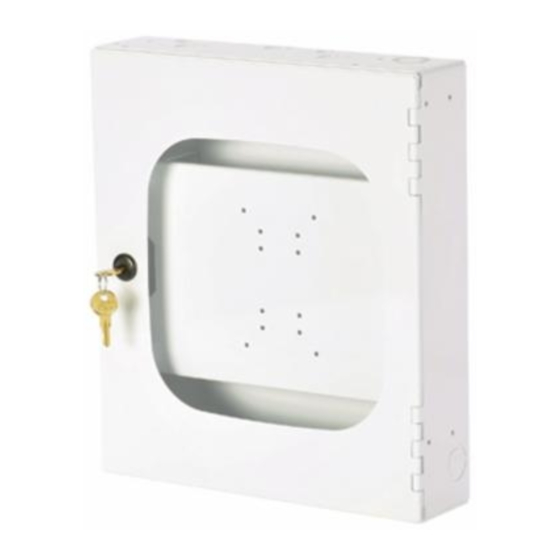
PZWC35
Knockouts
for Surface
Raceway
Mounting Plate for
Wireless Access Point
Installation (included)
TABLE OF CONTENTS
Mounting Guide................................................................................................................. 2-4
Wireless Access Point Installation..................................................................................... 5-6
For Technical Support: www.panduit.com/resources/install_maintain.asp
P
Part Number: PZWC35, PZWC35e
INSTALLATION INSTRUCTIONS
Key
#10-32 threaded
Grounding Studs and
Grounding Wire (included)
PZWC35
Z
Wireless Access Point Enclosure
AN
ONE
PZWC35e
Mounting Plate for
Wireless Access Point
Installation (included)
Page 1 of 6
Keyed Knockout Slots for Wall
Mount applications (6 places)
Double Knockout for 1/2" or 3/4"
Conduit (3 Places)
Knockout view (applies to PZWC35 and PZWC35e)
Knockouts
#10-32 threaded
for Surface
Grounding Studs and
Raceway
Grounding Wire (included)
Knockouts for Wireless
Access Point Antennae
PZWC35e
CM501A
(door removed from
view for clarity)
Page (s)
Advertisement

Related Manuals for Panduit PANZONE PZWC35


Summary of Contents for Panduit PANZONE PZWC35
- Page 1 Wireless Access Point Enclosure Part Number: PZWC35, PZWC35e INSTALLATION INSTRUCTIONS CM501A © Panduit Corp. 2010 List of Hardware Components (PZWC35 and PZWC35e): Keyed Knockout Slots for Wall (4)#8-32 X 1/4” Screws Mount applications (6 places) (2)Keys (door removed from view for clarity) Double Knockout for 1/2”...
-
Page 2: Wall Mount Installation
1/2” or 3/4” conduit. For Surface Raceway - Remove knockout “D” or “E”. This opening accommodates PANDUIT LD10 surface raceway. 1.2 Locate the wall studs. Position the enclosure on the wall and identify which keyed knockouts should be removed. It is recommended that two of the mounting holes be aligned with the wall stud. - Page 3 Please read these instructions in their entirety prior to installing the enclosure. Note: P Enclosures Require one of the following additional part numbers for in ceiling applications PANDUIT Part #:PZWIFIDCB - P Wireless Access PANDUIT Part #:PZW2X2DCB - P Wireless Access Point Point In Ceiling Bracket Kit In Ceiling 2’x 2’...
- Page 4 6.10 To secure the enclosure, wrap each hanger wire tightly around itself a minimum of three times. 6.11 Replace the adjacent ceiling tile. For Technical Support: www.panduit.com/resources/install_maintain.asp Page 4 of 6...
- Page 5 8.2 AP-Universal Bracket: Mount vendor- supplied wireless access point mounting frame to The Panduit-supplied Wireless Access Point Mounting Plate using Panduit- supplied (4) #8-32 X 1/4" Screws. Holes are aligned to inner rectangular orientation Vendor-Supplied wireless...
- Page 6 10.3 Secure with the Nuts and Washers that are on the stud. PZWE35 shown PZWC35 with completed Wireless PZWC35e with completed Wireless Access Point Assembly Access Point Assembly E-mail: For Instructions in Local Languages cs@panduit.com and Technical Support: Fax: www.panduit.com/resources/install_maintain.asp www.panduit.com (708) 444-6448 Page 6 of 6...
Need help?
Do you have a question about the PANZONE PZWC35 and is the answer not in the manual?
Questions and answers