Advertisement
Quick Links
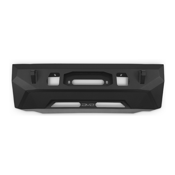
CENTRIC FRONT BUMPER
10-23 TOYOTA 4RUNNER
FBTF3-01
TOOLS
REQUIRED
- #4 Allen Bit
- 10, 21, 22mm Wrench
- 14, 15mm Socket
- 10" Extension
- Paint (Recommended)
- Cutting Tool of Choice
- File
WARNINGS/CAUTIONS BEFORE STARTING INSTALLATION
Before you install this kit —
instructions, warnings, cautions, and notes contained in
this installation instruction guide. Consult your vehicle
owner's manual for proper disconnection of electrical and
lifting of vehicle if required for installation of this product.
This install may require some technical skills and
knowledge of basic mechanical work. If you do not feel that
you are capable of performing this install please take this
product to a trained professional.
After reading this guide please contact us with any
questions or concerns before installing product.
Customer Service: 855-680-9595
DV8 Offroad is not responsible for any bodily injury or harm to you
or your vehicle as a result of an improper install.
6400 SYCAMORE CANYON BLVD.
RIVERSIDE, CALIFORNIA 92507
855-680-9595
WWW.DV8OFFROAD.COM
SKILL
LEVEL
- Novice/Intermediate
- 2 persons
Little skill level required, however
additional assistance is required for
installation and removal of bum-
pers.
Read and understand all
PRODUCT
INSTALLATION
TIME
- 3 hours
Time to install this should only
take about three hours.
Proper installation of this kit required knowledge of the factory
recommended procedures for removal and installation of original
equipment components. We recommend that the factory shop manual
and any special tools needed to service your vehicle be on hand during
the installation. Installation of this kit without proper knowledge of the
factory recommended procedures may affect the performance of these
components and the safety of the vehicle
• Always wear eye protection when operating power tools
Inspect all contents of this package to make sure product is not damaged
and all installation hardware has been included. If parts are missing from
kit, please be prepared to provide the following information
1. Name of purchase location
2. Bar Code on side of box
3. Date above bar code
4. Date inside box cover
NEED HELP?
MANUAL
REQUIRED
855-680-9595
Advertisement

Subscribe to Our Youtube Channel
Related Manuals for DV8 OFFROAD FBTF3-01


Summary of Contents for DV8 OFFROAD FBTF3-01
- Page 1 1. Name of purchase location Customer Service: 855-680-9595 2. Bar Code on side of box DV8 Offroad is not responsible for any bodily injury or harm to you 3. Date above bar code or your vehicle as a result of an improper install.
- Page 2 INSTALLATION MANUAL STEP 1 | Use a trim clip tool to remove the plastic fasteners securing the valance to the grille and set it off to the side. STEP 2 | Use a 10mm socket to remove the bolts securing the grille supports to the vehicle.
- Page 3 INSTALLATION MANUAL STEP 3 | Use a trim clip tool to remove the plastic fasteners securing the grille to the vehicle. NEED HELP? 855-680-9595...
- Page 4 INSTALLATION MANUAL STEP 4 | Disconnect any electrical/ wiring connectors. The number of connectors to remove may vary based on the trim level of your vehicle. STEP 5 | Use a 10mm socket to remove the hardware securing the inner fender to the front bumper.
- Page 5 INSTALLATION MANUAL STEP 7 | Use a 10mm socket to remove the hardware securing the bottom corners of the front bumpers to the vehicle. STEP 8 | Gently pull the inner fender to release the clips securing it to the vehicle.
- Page 6 INSTALLATION MANUAL STEP 10 | Carefully remove the bumper and set it on a soft surface/ blanket to avoid scratching/damaging the bumper. STEP 11 | Disconnect the bumper wiring harness. To disconnect, rotate the white locking tab and then pull to remove. NEED HELP? 855-680-9595...
- Page 7 INSTALLATION MANUAL STEP 12 | Use a 14mm socket to remove the hardware securing the crash bar to the vehicle. There are four on each side. NEED HELP? 855-680-9595...
- Page 8 INSTALLATION MANUAL STEP 13 | If you are installing a winch with a top mounted solenoid, trimming this hose support will be necessary to clear the winch. Use cutting tool of choice and use a file to clean up any rough edges. Paint is recommended on any bare metal to prevent corrosion/rust.
- Page 9 INSTALLATION MANUAL STEP 14 | Use a trim clip tool to remove the fasteners securing the wiring across the bottom face of the bumper. The amount of wiring and number of fasteners to remove will vary based on options/trim level. STEP 15 | Use a trim clip tool or flathead screwdriver to remove the plastic...
- Page 10 INSTALLATION MANUAL STEP 16 | Remove the valance and set it off to the side. STEP 17 | Move and secure the wiring out of the way to prepare to trim the bumper. STEP 18 | Remove the grille from the bumper by using a trim clip tool or flat head screwdriver to gently pull back the tabs securing the grille.
- Page 11 INSTALLATION MANUAL STEP 19 | READ STEPS 19 and 20 FULLY BEFORE PROCEEDING. The first cut line will be along the inside edge as close to the raised section of the bumper as possible(This is where the silver valance was mounted before, this section will be removed).
- Page 12 INSTALLATION MANUAL CUTTING REFERENCE PHOTOS NEED HELP? 855-680-9595...
- Page 13 INSTALLATION MANUAL Begin by unpacking all items and inspecting for missing pieces or damage. If you have any concerns, please contact the company the product was purchased from. Extra hardware may be included with the product. HARDWARE INCLUDED (6) M14x35 Hex (6) Spring Washer (6) M14 Nylon Lock Nuts (5) M6x20 Allen...
- Page 14 INSTALLATION MANUAL STEP 23 | If you are installing a 20” single row light bar, do so at this time using the hardware provided with the light. For our install, we are using a DV8 20” Elite Series Single Row Light Bar. Part Number: BE20SW105W STEP 24 | When securing the...
- Page 15 INSTALLATION MANUAL STEP 26 | If you are installing a winch, install winch/winch plate combo now using the provided M14 hardware with a 21 and 22mm socket. STEP 27 | With assistance, lift the bumper to the vehicle and secure it to the vehicle using the factory hardware with a 14mm socket.
- Page 16 INSTALLATION MANUAL STEP 28 | Place the grille/bumper onto the vehicle and secure it using the factory hardware with a 10mm socket and extension. Prior to continuing the install, inspect the cut of the bumper and fitment of the center mount and ensure no additional trimming or filing needs to be done.
- Page 17 INSTALLATION MANUAL STEP 31 | Re-install the edges of the bumper to the fender by pressing the clips into place. STEP 32 | Use the factory hardware with a 10mm socket to secure the bottom corners of the bumper to the vehicle. NEED HELP? 855-680-9595...
- Page 18 INSTALLATION MANUAL STEP 33 | Re-install the factory hardware securing the inner fender to the bumper using a 10mm socket. STEP 34 | Connect the fog light wiring harness ensuring the connector is fully seated. STEP 35 | Re-install the factory trim clips securing the grille to the vehicle.
- Page 19 INSTALLATION MANUAL STEP 36 | Use a 10mm socket to install the factory hardware securing the grille support to the vehicle. STEP 37 | Re-install the remaining trim clips securing the valance to the grille. NEED HELP? 855-680-9595...
- Page 20 INSTALLATION MANUAL STEP 38 | Congratulations! You are finished with the install of the DV8 Center Mount Bumper! NEED HELP? 855-680-9595...
Need help?
Do you have a question about the FBTF3-01 and is the answer not in the manual?
Questions and answers