Advertisement
Quick Links
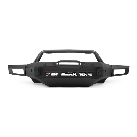
SPEC SERIES WINCH FRONT BUMPER
22+ Bronco Raptor
FBFR-01
TOOLS
REQUIRED
- 13mm, 15mm, 16mm, 18mm Socket
- 19mm Deep Socket
- 4mm Allen Bit
- T40 Torx Bit/Torx Plus 40
- Trim Clip Tool
WARNINGS/CAUTIONS BEFORE STARTING INSTALLATION
Before you install this kit —
instructions, warnings, cautions, and notes contained in
this installation instruction guide. Consult your vehicle
owner's manual for proper disconnection of electrical and
lifting of vehicle if required for installation of this product.
This install may require some technical skills and
knowledge of basic mechanical work. If you do not feel that
you are capable of performing this install please take this
product to a trained professional.
After reading this guide please contact us with any
questions or concerns before installing product.
Customer Service: 855-680-9595
DV8 Offroad is not responsible for any bodily injury or harm to you
or your vehicle as a result of an improper install.
6400 SYCAMORE CANYON BLVD.
RIVERSIDE, CALIFORNIA 92507
855-680-9595
WWW.DV8OFFROAD.COM
SKILL
LEVEL
- Novice/Intermediate
- 2 persons
Little skill level required, however,
assistance is required for
installation and removal of
bumpers.
Read and understand all
INSTALLATION
PRODUCT
TIME
- 4 Hours
Time to install this should only
take about 4 hours.
Proper installation of this kit required knowledge of the factory
recommended procedures for removal and installation of original
equipment components. We recommend that the factory shop manual
and any special tools needed to service your vehicle be on hand during
the installation. Installation of this kit without proper knowledge of the
factory recommended procedures may affect the performance of these
components and the safety of the vehicle
• Always wear eye protection when operating power tools
Inspect all contents of this package to make sure product is not damaged
and all installation hardware has been included. If parts are missing from
kit, please be prepared to provide the following information
1. Name of purchase location
2. Bar Code on side of box
3. Date above bar code
4. Date inside box cover
MANUAL
REQUIRED
855-680-9595
NEED HELP?
Advertisement

Related Manuals for DV8 OFFROAD FBFR-01


Summary of Contents for DV8 OFFROAD FBFR-01
- Page 1 1. Name of purchase location Customer Service: 855-680-9595 2. Bar Code on side of box DV8 Offroad is not responsible for any bodily injury or harm to you 3. Date above bar code or your vehicle as a result of an improper install.
- Page 2 INSTALLATION MANUAL STEP REMOVAL OF FACTORY STEEL BUMPER Begin by removing the front plastic d-ring guard. Using a screwdriver or push pin remover, remove the (17) pins across the d-ring guard. Pull the D-ring guard away from the Bronco firmly and set to the side. STEP Loosen the (6) bumper bolts.
- Page 3 INSTALLATION MANUAL STEP Once all bolts are loose, remove the plug for the fog lights and front sensors if equipped. This is located at the back end of the grill on the driver side. STEP Once unplugged, remove all (6) bumper bolts.
- Page 4 INSTALLATION MANUAL STEP Remove the rubber/plastic shroud under the grill by pulling the tabs on the shroud using a trim tool STEP If you do not have adaptive cruise control, remove the plastic cover by pushing the clip on the top down while pulling away from Bronco, and set off to the side.
- Page 5 INSTALLATION MANUAL STEP Using a 15mm socket, remove the (4) skid plate bolts and factory skid plate. 855-680-9595 NEED HELP?
- Page 6 INSTALLATION MANUAL STEP If equipped with sensors, remove the main bumper brackets/D-rings from the backside of the bumper using a 13mm socket, remove the (4) hex head bolts. STEP Remove the fog light rear housing. Using a trim tool, remove the (4) push pins on each side.
- Page 7 INSTALLATION MANUAL STEP Using a T40 Torx Bit (or Torx Plus 40), remove the bumper bolts. STEP STEP 855-680-9595 NEED HELP?
- Page 8 INSTALLATION MANUAL To remove the wire harness, using a flat head screwdriver or push pin puller, remove all the retaining clips securing the harness to the bumper. STEP To remove the sensors, spread the two tabs on the sensor bezel and gently pull up on the sensor.
- Page 9 INSTALLATION MANUAL STEP Begin by unpacking all items and inspecting for missing pieces or damage. If you have any concerns, please contact the company the product was purchased from. Hardware Included: (3) M8x40 Hex (4) M12x35 Hex (3) M8 Flat Washers (8) M12 Flat Washers (9) M8 Spring Washers (4) M12 Nylon Nuts...
- Page 10 INSTALLATION MANUAL STEP Apply the adhesive side of the provided foam to the bull bar. STEP Use the provided M8 nuts and bolts with a 5mm Allen bit & 13mm wrench or socket to secure the bull bar to the bumper.
- Page 11 INSTALLATION MANUAL STEP For the two center sensors, you will need to cut back or peel back the wiring loom of the bumper wiring harness. Once the wiring is exposed, gently pull the center sensors away from each other. This will create extra length in the harness needed for all sensors to reach their install location.
- Page 12 INSTALLATION MANUAL STEP Feed the bumper wiring harness through the access holes in the bumper. The plug that connects to the vehicle should be on the driver side. The sensors should be at their approximate location of install. If you do not have a wiring harness, skip to the next step.
- Page 13 INSTALLATION MANUAL STEP Install the sensors bezels by pressing them into place. These are keyed for installation, and should easily pop into place. You can also reference the bezel for correct placement, Example: “ROR” means “Rear Outer Right” If not equipped with sensors, use provided sensor plugs.
- Page 14 INSTALLATION MANUAL STEP Ensure any wiring is secure and will not pinched during the install of the bumper using the wiring access holes. Utilize built in zip tie tabs to secure any wiring. . STEP If you are installing a 20” single row LED light bar, do so at this time using the provided mounting bracket.
- Page 15 INSTALLATION MANUAL STEP If you are installing a winch, do so at this time using the hardware provided with the winch. There is an additional access hole near the passenger side mount for running the wiring from the winch. If you are not installing a winch, skip to the next step.
- Page 16 INSTALLATION MANUAL STEP With assistance, lift the bumper to the vehicle and loosely secure it using the provided M10 hardware with a 16mm socket. Ensure the wiring is not being pinched between the bumper and vehicle. Adjust the bumper up/down as necessary to sit even.
- Page 17 INSTALLATION MANUAL STEP Secure the skid plate to the bumper using the provided M8 hardware with a 13mm socket. The holes in the skid plate allow for access to reach the mounting locations. Then finish securing the skid plate by securing the factory hardware and a 16mm socket.
- Page 18 INSTALLATION MANUAL STEP Double check fitment and all hardware is secure. Congratulations, you are finished with the install of the 22+ Ford Bronco Raptor Spec Series Front Winch Bumper. 855-680-9595 NEED HELP?
Need help?
Do you have a question about the FBFR-01 and is the answer not in the manual?
Questions and answers