Advertisement
Quick Links
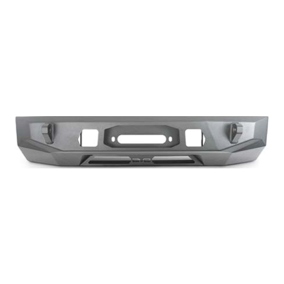
CENTER MOUNT
2022+ (3RD GEN) TOYOTA TUNDRA
FBTT2-05
TOOLS
REQUIRED
- 10mm,21mm,22mm Sockets
- 10mm, 18mm, 19mm, 21mm, 22mm
Wrenches
- 4mm Allen Bit
- Trim Clip Tool
- Flat Head Screwdriver
- Preferred cutting tool
- File or Sandpaper
- Marker/Sharpie
WARNINGS/CAUTIONS BEFORE STARTING INSTALLATION
Before you install this kit —
instructions, warnings, cautions, and notes contained in
this installation instruction guide. Consult your vehicle
owner's manual for proper disconnection of electrical and
lifting of vehicle if required for installation of this product.
This install may require some technical skills and
knowledge of basic mechanical work. If you do not feel that
you are capable of performing this install please take this
product to a trained professional.
After reading this guide please contact us with any
questions or concerns before installing product.
Customer Service: 855-680-9595
DV8 Offroad is not responsible for any bodily injury or harm to you
or your vehicle as a result of an improper install.
6400 SYCAMORE CANYON BLVD.
RIVERSIDE, CALIFORNIA 92507
855-680-9595
WWW.DV8OFFROAD.COM
SKILL
LEVEL
- Intermediate/Difficult
- 2 persons
Intermediate skill level required.
Assistance is necessary for
installation.
Read and understand all
PRODUCT
INSTALLATION
TIME
- 4-6 Hours
Time to install this should take
between 4-6 hours based on
experience.
Proper installation of this kit required knowledge of the factory
recommended procedures for removal and installation of original
equipment components. We recommend that the factory shop manual
and any special tools needed to service your vehicle be on hand during
the installation. Installation of this kit without proper knowledge of the
factory recommended procedures may affect the performance of these
components and the safety of the vehicle
• Always wear eye protection when operating power tools
Inspect all contents of this package to make sure product is not damaged
and all installation hardware has been included. If parts are missing from
kit, please be prepared to provide the following information
1. Name of purchase location
2. Bar Code on side of box
3. Date above bar code
4. Date inside box cover
NEED HELP?
MANUAL
REQUIRED
855-680-9595
Advertisement

Related Manuals for DV8 OFFROAD FBTT2-05


Summary of Contents for DV8 OFFROAD FBTT2-05
- Page 1 1. Name of purchase location Customer Service: 855-680-9595 2. Bar Code on side of box DV8 Offroad is not responsible for any bodily injury or harm to you 3. Date above bar code or your vehicle as a result of an improper install.
- Page 2 INSTALLATION MANUAL FACTORY BUMPER UNINSTALL STEP 1 | Use a 10mm socket to remove the fasteners securing the fender flare to the vehicle. STEP 2 | Using firm pressure, pull the fender flare away from the truck to the side to release the clips. Once released, pull the side of the bumper down slightly and to the side to release the clips between the bumper and fender.
- Page 3 INSTALLATION MANUAL STEP 4 | Use a trim clip tool to remove the push clips next to the wiring plugs located next to the headlights at both ends of the vehicle. Then disconnect the plugs. Note: Number of wire connectors may vary based on options/trim level of the vehicle.
- Page 4 INSTALLATION MANUAL STEP 6 | Use a trim clip tool to remove the fasteners securing the wiring plugs located behind the bumper in the fender well area on both sides of the vehicle. Then disconnect the plugs. STEP 7 | Disconnect the wiring plugs located behind the grille on the passenger side of the vehicle underneath the grille’s...
- Page 5 INSTALLATION MANUAL STEP 8 | Use a 10mm socket to remove the bolts securing the grille to the vehicle. These are located: -Along the radiator frame brace under the hood. -Underneath the vehicle along the bottom of the bumper. -Behind the trim pieces on both sides of the vehicle underneath the headlights.
- Page 6 INSTALLATION MANUAL STEP 10 | Use a 17mm socket or wrench to remove the bolts securing the crash bar. Then set the crash bar and braces off to the side. Some vehicles came equipped with an air dam motor. If the vehicle has an air dam motor, unplug and remove it at this time.
- Page 7 INSTALLATION MANUAL STEP 12 | Use a 10mm socket to remove the bolt securing the cooling hose bracket and set off to the side. STEP 13 | Use a 12mm socket to remove the bolts securing the skid plate if you have one, and set it off to the side.
- Page 8 INSTALLATION MANUAL Begin by unpacking all items and inspecting for missing pieces or damage. If you have any concerns, please contact the company the product was purchased from. Extra hardware may be included with the product. HARDWARE INCLUDED (12) M14x35 Hex Bolts (1) M8x30 Hex Bolt (24) M14 Flat Washers (3) M6x25 Allen...
- Page 9 INSTALLATION MANUAL STEP 15 | Unclip bumper trim pieces to allow removal of Bumper Face. Remove Bumper Face. STEP 16 | Using a Pry Tool, unclip the 5 wiring harness hold downs. NEED HELP? 855-680-9595...
- Page 10 INSTALLATION MANUAL STEP 17 | Secure the wring harness out of the way with zip ties. STEP 18 | With the bumper face removed and wiring harness’s secured out of the way, use a marker to draw a cut line. When cutting the area below the mesh, the cut line should be above the clips.
- Page 11 INSTALLATION MANUAL STEP 19 | Using your preferred cutting tool, cut the bumper following the cut line previously drawn. Use a File or sandpaper to smooth out any rough edges STEP 20 | Using a 5mm Allen bit, 13mm wrench and provided M8 hardware attach the bumper support brackets to each side of the DV8 center mount.
- Page 12 INSTALLATION MANUAL STEP 21 | If planning to run a light bar or pod lights install those accessory’s at this time. Using a 4mm Allen bit, 10mm wrench and provided M6 hardware install light bar brackets with button head on top to allow for winch plate clearance.
- Page 13 INSTALLATION MANUAL STEP 22 | On the air dam motor use a trim clip tool to remove the cap. Then use a 14mm socket and wrench to remove the bolts and nut securing the arm. STEP 23 | Remove the black caps, the white plastic spacers and the spring from the inside, and set the arm off to the side.
- Page 14 INSTALLATION MANUAL STEP 24 | Cut the flat section off of the arm as shown. STEP 25 | Place the arm back into the motor and install the spring, white plastic spacers, and black caps. Then secure using the factory hardware with a 14mm wrench and socket.
- Page 15 INSTALLATION MANUAL STEP 26 | Trim the plastic section with the two factory mounting holes off of the motor as shown. HOLES WITH THE ARROWS WILL BE REUSED, DO NOT CUT THESE STEP 27 | Trim the small remaining mounting tab off the motor as shown. NEED HELP? 855-680-9595...
- Page 16 INSTALLATION MANUAL STEP 28 | Replace cap on the air dam motor. STEP 29 | Use a 10mm socket to remove the bolt securing the cooling hoses to bracket located in front of the radiator on the passenger side. NEED HELP? 855-680-9595...
- Page 17 INSTALLATION MANUAL STEP 30 | Remove the cooling hoses running in front of the radiator from their plastic retaining clips. STEP 31 | Use a 10mm socket to remove the bolt securing the vertical cross brace. Slip the cooling hose behind the cross brace and re-secure using the factory hardware.
- Page 18 INSTALLATION MANUAL STEP 32 | On the passenger side, push back on the hose mounting bracket to give the hoses some slack and then re-secure the hoses using the factory hardware and a 10mm socket. Replace the upper cooling hose in its plastic retaining clips Tip: Zip tie the lower cooling hose to the center brace at this time ensuring it clears the winch...
- Page 19 INSTALLATION MANUAL STEP 35 | Secure air dam motor wiring harness to vertical center cross brace using the factory clip. Note: Air dam motor should have a healthy gap between it and the radiator. The radiator hose running behind the air dam motor should not be too taught or too loose, and should also have a gap between it and the radiator.
- Page 20 INSTALLATION MANUAL STEP 36 | If planning to utilize a winch, install the winch on to the winch plate at this time using hardware supplied in winch kit. Using a 21mm socket, 22mm & 21mm wrench and provided M14 hardware, install the winch and winch plate on to the DV8 center mount.
- Page 21 INSTALLATION MANUAL STEP 38 | Optional Step: Provided are (2) Center Mount Spacers, these spacer provide a slight gap between the center mount and grille. If a flush install finish is desired do not install center mount spacers. Using a 21mm socket, 22mm wrench and provided M14 hardware secure the spacer plates to the center mount.
- Page 22 INSTALLATION MANUAL STEP 40 | Carefully reattach fender flares by pressing the clips into place. NEED HELP? 855-680-9595...
- Page 23 INSTALLATION MANUAL STEP 41 | Reattach the bumper on each side to the wheel well using a 10mm socket and the (6) factory hardware previously removed. The factory inner fender should be sandwiched between the bumper and fender flare. STEP 42 | Reattach the bumper to the fender liner using a 10mm socket and factory hardware previously removed.
- Page 24 INSTALLATION MANUAL STEP 44 | Reattach the top of the grille using factory hardware previously removed and a 10mm socket. STEP 45 | Install all push pins and reconnect all wiring harness’s previously removed or disconnected. NEED HELP? 855-680-9595...
- Page 25 INSTALLATION MANUAL STEP 46 | Double check that all hardware is secure. Congratulations the DV8 Center Mount installation is now complete. NEED HELP? 855-680-9595...
Need help?
Do you have a question about the FBTT2-05 and is the answer not in the manual?
Questions and answers