Advertisement
Quick Links
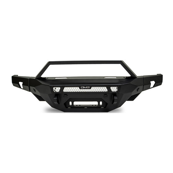
MTO V2 FRONT BUMPER
2021+ FORD BRONCO
FBBR-07
TOOLS
REQUIRED
- 4mm Allen Bit
- 10, 13, 15, 18, 21mm Sockets
- 10, 22mm Wrench
- T40 Torx Bit
- Zip Ties
- Trim Tool
WARNINGS/CAUTIONS BEFORE STARTING INSTALLATION
Before you install this kit —
instructions, warnings, cautions, and notes contained in
this installation instruction guide. Consult your vehicle
owner's manual for proper disconnection of electrical and
lifting of vehicle if required for installation of this product.
This install may require some technical skills and
knowledge of basic mechanical work. If you do not feel that
you are capable of performing this install please take this
product to a trained professional.
After reading this guide please contact us with any
questions or concerns before installing product.
Customer Service: 855-680-9595
DV8 Offroad is not responsible for any bodily injury or harm to you
or your vehicle as a result of an improper install.
555 E Queen Creek Rd
Chandler, AZ 85286
855-680-9595
WWW.DV8OFFROAD.COM
SKILL
LEVEL
- Novice/Intermediate
- 2 to 3 people
Intermediate skill level required.
Additional help will be needed
when removing and installing
bumpers.
Read and understand all
INSTALLATION
PRODUCT
TIME
- Approximately 4-4.5 Hours
Time to install this should
take about four to four and a
half hours
Proper installation of this kit required knowledge of the factory
recommended procedures for removal and installation of original
equipment components. We recommend that the factory shop manual
and any special tools needed to service your vehicle be on hand during
the installation. Installation of this kit without proper knowledge of the
factory recommended procedures may affect the performance of these
components and the safety of the vehicle
• Always wear eye protection when operating power tools
Inspect all contents of this package to make sure product is not damaged
and all installation hardware has been included. If parts are missing from
kit, please be prepared to provide the following information
1. Name of purchase location
2. Bar Code on side of box
3. Date above bar code
4. Date inside box cover
MANUAL
REQUIRED
855-680-9595
NEED HELP?
Advertisement

Related Manuals for DV8 OFFROAD FBBR-07


Summary of Contents for DV8 OFFROAD FBBR-07
- Page 1 1. Name of purchase location Customer Service: 855-680-9595 2. Bar Code on side of box DV8 Offroad is not responsible for any bodily injury or harm to you 3. Date above bar code or your vehicle as a result of an improper install.
- Page 2 INSTALLATION MANUAL STEP REMOVAL OF FACTORY STEEL BUMPER Begin by removing the front plastic d-ring guards. Using a screwdriver or trim clip tool, remove the (2) pins on the bottom and (2) near the top of the d-ring mount. Pull the top half away from the Bronco and set to the side.
- Page 3 INSTALLATION MANUAL STEP Once all bolts are loose, remove the plug for the fog lights and front sensors if equipped. This is located at the back end of the grill on the driver side. If you do not have these, skip ahead to step 4.
- Page 4 INSTALLATION MANUAL STEP Remove the rubber/plastic shroud under the grill by pulling the tabs on the shroud away (up/down) from vehicle while pulling the shroud from the vehicle. STEP If you do not have adaptive cruise control, remove the plastic cover by pushing the clip on the top down while pulling away from Bronco, and set off to the side.
- Page 5 INSTALLATION MANUAL STEP If equipped with sensors, remove the main bumper brackets from the backside of the bumper using a 13mm socket, remove the (4) hex head bolts. STEP Next, using a T40 torx bit, remove the (6) bolts securing the mount in place. Once removed, gently separate mount from bumper, and set off to the side.
- Page 6 INSTALLATION MANUAL STEP To remove the wire harness, using a flat head screwdriver or pin puller, remove all the retaining clips securing the harness to the bumper. STEP To remove the sensors, spread the two tabs on the sensor bezel and gently pull up on the sensor.
- Page 7 INSTALLATION MANUAL STEP INSTALLATION OF DV8 BUMPER Begin by unpacking all items and inspecting for missing pieces or damage. If you have any concerns, please contact the company the product was purchased from. Hardware Included: (6) M12 Spring Washers (6) M14x35mm Bolts (6) M12 Enlarge Washer (6) M14 Lock Nuts...
- Page 8 INSTALLATION MANUAL STEP Using the M14 hard, mount the wings to the center section of the bumper. Ensure the top and face are flush. Using a 21 and 22mm socket/ wrench secure wings until tight. STEP To install the bull bar, install the provided foam, and mount the bar using the provided M6 hex head bolts.
-
Page 9: Installation
INSTALLATION MANUAL STEP Once the bull bar is mounted, if you are running a light bar, mount the provided brackets to the bull bar using the M8 bolts and 13mm socket and wrench. Note: Orientation of the brackets may differ depending on the size and make of light bar. - Page 10 INSTALLATION MANUAL STEP If running a 20” single row behind the mesh on the center portion of bumper, using the hardware provided with the lights, mount the brackets to the light as shown. STEP Using the provided M6 hardware, secure the light bar to the bumper (2) per side.
- Page 11 INSTALLATION MANUAL STEP The wings of the bumper can accept (2) 3” pod lights. Using the factory hardware provided with the light, mount them to each wing and secure. STEP Once lights are installed, using the built in zip tie tabs, sure wiring in the bumper.
- Page 12 INSTALLATION MANUAL STEP If equipped with front parking sensors, lay out the harness and route the sensors near corresponding plug opening and ensure that the main plug for the harness is laying on the driver side. 855-680-9595 NEED HELP?
- Page 13 INSTALLATION MANUAL STEP The sensor bezels on the capable bumper are slightly different and may require trimming. Reference the bezel for correct placement if you are unsure of where to install them. These are keyed for installation. Determine if the sensor bezels need to be trimmed for installation on the DV8 Bumper by placing the bezels up to the corresponding mounting hole...
- Page 14 INSTALLATION MANUAL STEP With the harness installed, using the provided zip tie mounts, secure the wiring. If running the DV8 camera relocation (ABBR-03), a new main camera mount is included with this bumper. Use this bracket and continue with the ABBR- 03 install guide.
- Page 15 INSTALLATION MANUAL STEP Install the M12 nut clips onto the mounting plates by pressing them until they “click” into place. They should move around for adjustment. Note the direction they are installed. 855-680-9595 NEED HELP?
- Page 16 INSTALLATION MANUAL STEP With all the wires secured/out of the way of the mounts, with assistance use the provided M12 hardware and mount the bumper onto the Bronco. Loosely install hardware. STEP With assistance, adjust the bumper until it is even against the lower valance of the grille.
- Page 17 INSTALLATION MANUAL STEP With the bumper mounted, plug in the main front harness located on the driver side under the grille. STEP Finish wiring the winch and any added lights and double check all hardware is secure. Congratulations, you are finished the install of the DV8 Bronco MTO V2 bumper! 855-680-9595...
Need help?
Do you have a question about the FBBR-07 and is the answer not in the manual?
Questions and answers