Advertisement
Quick Links
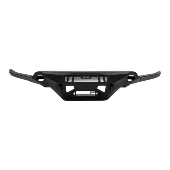
COLORADO FRONT SPEC BUMPER
23+ ChEVY ColoRADO
FBCS3-01
TOOLS
REQUIRED
- T15 Torx Bit
- 7mm, 10mm, 13mm, 15mm, 18mm,
19mm Sockets
- #2.5 #4, #5 Allen Bit
- Push Pin Tool
- Cutting Tool
- Marker
WARNINGS/CAUTIONS BEFORE STARTING INSTALLATION
Before you install this kit —
instructions, warnings, cautions, and notes contained in
this installation instruction guide. Consult your vehicle
owner's manual for proper disconnection of electrical and
lifting of vehicle if required for installation of this product.
This install may require some technical skills and
knowledge of basic mechanical work. If you do not feel that
you are capable of performing this install please take this
product to a trained professional.
After reading this guide please contact us with any
questions or concerns before installing product.
Customer Service: 855-680-9595
DV8 Offroad is not responsible for any bodily injury or harm to you
or your vehicle as a result of an improper install.
555 E Queen Creek Rd
Bldg A
Chandler, AZ 85286
WWW.DV8OFFROAD.COM
SKILL
LEVEL
- Intermediate
- 1 (you) to 2 persons
Medium skill level required, you can
easily install it by yourself however,
additional help will be useful
Read and understand all
INSTALLATION
PRODUCT
TIME
- 6.5 Hour
Time to install this should take
about six and half hours
Proper installation of this kit required knowledge of the factory
recommended procedures for removal and installation of original
equipment components. We recommend that the factory shop manual
and any special tools needed to service your vehicle be on hand during
the installation. Installation of this kit without proper knowledge of the
factory recommended procedures may affect the performance of these
components and the safety of the vehicle
• Always wear eye protection when operating power tools
Inspect all contents of this package to make sure product is not damaged
and all installation hardware has been included. If parts are missing from
kit, please be prepared to provide the following information
1. Name of purchase location
2. Bar Code on side of box
3. Date above bar code
4. Date inside box cover
NEED HELP?
MANUAL
REQUIRED
855-680-9595
Advertisement

Related Manuals for DV8 OFFROAD FBCS3-01


Summary of Contents for DV8 OFFROAD FBCS3-01
- Page 1 1. Name of purchase location Customer Service: 855-680-9595 2. Bar Code on side of box DV8 Offroad is not responsible for any bodily injury or harm to you 3. Date above bar code or your vehicle as a result of an improper install.
- Page 2 INSTALLATION MANUAL Begin by unpacking all items and inspecting for missing pieces or damage. If you have any concerns, please contact the company the product was purchased from. Extra hardware may be included with the product. HARDWARE INCLUDED (4) M12x80mm Hex bolts bolts (4) M12 Lock nuts (8) M8 Washers...
- Page 3 INSTALLATION MANUAL STEP 3 | Peel back the inner fender and remove the (2) bolts securing the bumper to the fender using a 7mm socket. STEP 4 | With a firm grip, separate the bumper from the fender. STEP 5 | Use a 13 mm socket to remove the (4) bolts securing the skid plate.
- Page 4 INSTALLATION MANUAL STEP 6 | Use a T15 torx tool to remove the (4) torx bolts that secures the lower bumper portion. STEP 7 | Start to pull the bumper/ grille assembly away from the vehicle. If equipped disconnect the fog lights and front camera harnesses on the passenger side.
- Page 5 INSTALLATION MANUAL STEP 8 | Use a 15mm socket to remove the (6) bolts that secures the crash bar to the frame rails. STEP 9 | Use a 10mm socket to remove the (4) bolts that secure the lower air shutter. Disconnect the shutter motor and set off to the side.
- Page 6 INSTALLATION MANUAL STEP 10 | Use a 18mm socket and wrench to remove the factory recovery hooks. STEP 11 | Use a 7mm socket to remove the bolts that secures the shutter shroud to crash bar. Once the (2) 7mm bolts are removed you can remove the crash bar.
- Page 7 INSTALLATION MANUAL STEP 13 | Mark the radiator shroud as shown. Use your preferred cutting tool to cut out a small section of the radiator shroud. STEP 14 | With the shroud cut it should look as shown. Assembly of the DV8 front bumper can now begin.
- Page 8 INSTALLATION MANUAL STEP 15 | Loosely install the winch plate supports onto the winch plate using the provided M8 Allen head bolts and M8 hardware. STEP 16 | Apply the provided peel and stick foam pieces on to the bumper wings as shown.
- Page 9 INSTALLATION MANUAL STEP 18 | If you are planning to run a LED light bar, install the light bar at this time using the provided light bar brackets. Attach the light bar brackets to the light bar using the hardware that comes with the LED light bar.
- Page 10 INSTALLATION MANUAL STEP 21 | Install the cover mounting plates using the provided tapered M6 hardware and an #4 Allen as shown. 855-680-9595 NEED HELP?
- Page 11 INSTALLATION MANUAL STEP 22 | Mount the cover plates to the mounting plates using the provided tapered M6 hardware and an #4 Allen tool. 855-680-9595 NEED HELP?
- Page 12 INSTALLATION MANUAL STEP 23 | Mount the skid plate to the bumper with(4) M8 Allen head bolts and M8 washers using a #5 allen head. STEP 24 | If planning to mount LED Pod lights do so at this time. Attach the LED pod light to the provided pod light bracket using the hardware provided with your chosen pod light.
- Page 13 INSTALLATION MANUAL STEP 26 | Remove the blades and set aside. Mark housing as shown to prepare for cutting. Be sure not to trim or cut the blade mounting points (green arrows). STEP 27 | Once marked, cut the motor housing away from the structure using a grinder or similar cutting tool.
- Page 14 INSTALLATION MANUAL STEP 28 | Take blade marked, and cut off the side mounted against the motor assembly. STEP 29 | Mark the round flat surface in the center as shown. Using a 3/16” drill bit, drill a hole though the center entering from the long end to ensure the hole is in the center.
- Page 15 INSTALLATION MANUAL STEP 30 | Reinstall the blade mount onto the motor same as factory, and using the M5 long bolt the mount onto the motor mount. STEP 31 | With the bolt inserted, press on the backside to score the housing and using the 3/16”: drill bit, carefully drill though to allow the bolt to be through bolted.
- Page 16 INSTALLATION MANUAL STEP 32 | Using a 2.5mm allen and 7mm socket/wrench, secure the bolt into place. STEP 33 | Once the assembly is complete, slide the motor into the mount on the skid plate and secure with two M6 bolts and nuts using a #4 and 10mm socket.
- Page 17 INSTALLATION MANUAL 855-680-9595 NEED HELP?
- Page 18 INSTALLATION MANUAL STEP 34 | With assistance lift the bumper into place. Use (3) provided M12 Hex head bolts per side and (1) M12 Allen head bolt to secure the bumper to the frame rails. STEP 35 | Reinstall the recovery hook using the provided M12x80 hardware, ensuring the bolts thread through the winch plate support brackets as shown.
- Page 19 INSTALLATION MANUAL STEP 37 | Secure the skid plate to front cross member using (2) of the factory skid plate bolts and a 13mm socket. STEP 38 | With the bumper mounted, remove the factory bumper/ grille assembly lower fascia. Use a trim clip tool to disconnect the factory clips holding the lower fascia.
- Page 20 INSTALLATION MANUAL STEP 39 | Mark the backside of the bumper as shown. Note: Trim lower than expected on the wings and check, removing a little each time until the plastic fits with the new bumper as desired. 855-680-9595 NEED HELP?
- Page 21 INSTALLATION MANUAL STEP 40 | Using your preferred cutting tool, cut off the lower bumper/ grille assembly. Note: Using painters tape on the front of the bumper helps keep a straight cut. Using a pry tool to slightly separate the grille and bumper prevents cutting too deep.
- Page 22 INSTALLATION MANUAL STEP 41 | Use a file or sanding disk to clean up any sharp edges or tabs. STEP 42 | Install the bumper/grille assembly on to the vehicle. Press the bumper clips back into place. If equipped, reconnect the fog light harness and front camera harness.
- Page 23 INSTALLATION MANUAL STEP 43 | Check that the cut is even across the bumper. Additional trimming my be required. Note: Edge trim can be installed on to the cut bumper for a more finished look if desired. 855-680-9595 NEED HELP?
- Page 24 INSTALLATION MANUAL STEP 44 | Secure the bumper to the fender using the (2) factory 7mm bolts on each side. STEP 45 | Use a T15 torx tool to secure the inner fender to the bumper/ grille assembly. Secure the top of the bumper/grille assembly to the radiator support using the factory hardware and a T15 torx tool.
- Page 25 INSTALLATION MANUAL STEP 46 | Double check that all hardware is secure and all electrical harnesses have been reconnected. Congratulations, installation of the DV8 23+ Colorado Front Spec Bumper is now complete. 855-680-9595 NEED HELP?
Need help?
Do you have a question about the FBCS3-01 and is the answer not in the manual?
Questions and answers