
Subscribe to Our Youtube Channel
Related Manuals for NIMO DC 120 WW


Summary of Contents for NIMO DC 120 WW
- Page 1 DC 120 WW 427001395 Keep this manual so that it is always available for future use. Drying Cabinet Service Manual...
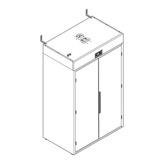
- Page 2 Connected permanently to separate duct or general ventilation Electrical connection for external fan Hangers Electrical connection to mains Door hangers 1200 1970 2035 1100 Identification plate Manufacturer: NIMO-VERKEN AB Box 288 542 23 Mariestad info@nimoverken.com www.nimoverken.com Doc. N0: 427001395 / 02...
-
Page 3: Table Of Contents
Contents Safety instructions ............. . 4 1.1 Symbols. -
Page 4: Safety Instructions
1 Safety instructions This advice on safe operation has been compiled to enable you to avoid incorrect use and unnecessary risks of accidents and should be read before the drying cabinet is installed and used. DO NOT MODIFY THIS PRODUCT The drying cabinet must be installed and kept indoors. -
Page 5: Symbols
Applicable to installation in countries outside the EU The appliance is not intended for use by persons (including children) with various disabilities or inadequate experience and knowledge. They may use the appliance only under supervision or if they have received instructions on how to use the appliance from a person who is responsible for their safety. -
Page 6: Air Flow
2 Air flow The cabinet operates with negative pressure in the drying space. Air is drawn in by two fans through an air intake in the top section of the cabinet and through the door gaps of the cabinet. The air is heated by three elements on the left side and three elements A m²... -
Page 7: Components Of The Fan Unit
3 Components of the fan unit Moisture sensor With electronic unit : See section 7.2. removed Viewed from below Temperature sensor, temperature of the cabinet. Temperature sensor, temperature of the cabinet. Left-hand side Right-hand side Terminal block, mains Fan motors Element Control panel Main control - Overheat cut-out... -
Page 8: Fan Motor And Condenser
4 Fan motor and condenser Fault tracing Function • If neither of the fans is running, check that there is power The cabinet has two fans that create correct air flow in the supply from the electronics. cabinet. • If one of the fans is not running, replace the associated condenser. The condenser creates correct operating conditions for the fan. -
Page 9: Door Switch
5 Door switch Function Fault tracing Starting regulation, the cabinet cannot start unless the door is closed. • Disconnect the power supply to the drying cabinet. If the door switch is not activated, the cabinet will not start. • Use multimeter with buzzer function. •... -
Page 10: Overheat Cut-Out
6 Overheat cut-out 6.1 Thermostat / Overheat cut-out for heat regulation Function Replacement of thermostat This overheat cut-out interrupts the drying process if the • Detach the flat blade contacts (2) in the faulty ther- cabinet becomes warmer than the set optimal value. The mostat. -
Page 11: Regulation Of Drying Process
7 Regulation of drying process Function The drying process is controlled by two temperature sensors, KTY81-110, and one moisture sensor. The moisture sensor reads off the cabinet moisture. If the sensors do not work properly, the laundry will not dry. 7.1 Temperature sensors Fault tracing Replacement of temperature sensor... -
Page 12: Moisture Sensor
7.2 Moisture sensor The moisture is installed in the fixing plate for a left-hand sor, HIH 4000. The drying process is interrupted when fan unit. air humidity in the cabinet has fallen to a set value. If the sensor does not work properly, the laundry will not dry Function fully or or will dry too much. -
Page 13: Heating Element
8 Heating element Function In measurement of a cold element, the resistance value must Generates heat in the cabinet. be between 48.8 and 56.7 ohms between element connection and ground. Fault tracing Carry out an isolation test, measure between outer casing The power supply to the drying cabinet must be discon- and element. -
Page 14: Control Panel
9 Control panel Function Program selector for the automatic drying programmes for im- pregnation of membrane garments or normal drying suitable for padded workwear/emergency services suits. 9.1 Replacement of control panel Disconnect the power supply to the cabinet before starting work. •... -
Page 15: Electronic Unit
11 Electronic unit Function Controlling the drying process. Fault tracing • Check the relay unit of the electronics (D). This closes a • Check that there is power supply to the electronics, 230V. circuit to the fan unit. Attachment at the two flat blades (C). •... -
Page 16: Setting Of Drying Programme
12 Setting of drying programme There are ways of optimising the two automatic programmes The values are displayed as follows: of the drying cabinet according to prevailing installation the top row of the display shows the current parameter, e.g. conditions. ”P 2195”, the bottom rowshows the set value. -
Page 17: Parameter Table
13 Parameter table ENGLISH... -
Page 18: Error Codes / Fault-Tracing Guide
14 Error codes / Fault-tracing guide Name Description / Action ERR 01 Error in left temperature sensor See section 7.1. for the cabinet temperature ERR 02 Error in right temperature See section 7.1. sensor for the cabinet temperature ERR 04 Max. -
Page 19: Technical Data
15 Technical data Capacity kg tvätt kg pyykkiä kg laundry Dewatering capacity g/min *) Electrical connection 400V 3N AC 50Hz Fuse protection slow, automatic fuse Motor 2 x 155 Heating element output: 6 x 1000 Overheat cut-out Ja/Kyllä/Yes Evacuated volume of air: m³/tim Detachable hangers Net weight... -
Page 20: Temperature Sensor Kty
16 Temperature sensor KTY Measurement table Ambient temperature, corresponding resistance, temperature coefficient and maximum expected temperature error for KTY81–110. I cont = 1 mA Ambient temperature Temp. coeff. KTY81-110 Resistance ( Ω ) °C °F Temp. error Typ. Max. 0,99 ±3,02 0,98 ±2,92...
Need help?
Do you have a question about the DC 120 WW and is the answer not in the manual?
Questions and answers