
Subscribe to Our Youtube Channel
Related Manuals for NIMO ECO Dryer 2.0 HP FT 60 VP


Summary of Contents for NIMO ECO Dryer 2.0 HP FT 60 VP
- Page 1 ECO Dryer 2.0 HP FT 60 VP 427000889 Keep this manual so that it is always available for Drying Cabinet Service Manual future use.
- Page 2 The manual also contains instructions for rehanging the door and disassembling the dehu- midifier unit. For a description of the drying cabinet, see the Installation and User Manual. Doc. No: 427000889 Rev. 02 Manufacturer: NIMO-VERKEN AB Box 124 Right to make changes reserved. S-548 22 HOVA Tel +46 (0)506 / 488 00...
-
Page 3: Table Of Contents
Contents The drying cabinet Wiring diagram Rehanging the door Dehumidifier unit – disassembly Programming Control panel Drying programmes Selection of drying programme Drying function Start the drying programme Stop the drying programme The door is opened Setting of drying programme Introduction Procedure Resetting to factory setting... -
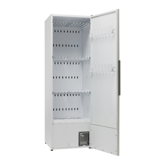
Page 4: The Drying Cabinet
The drying cabinet Wall attachment Extendable hanging sections (3x) Door hangers Detachable shoe rack Tank for condensation water Dehumidifier unit Adjustable feet (4x) Service manual... -
Page 5: Wiring Diagram
Wiring diagram Wiring diagram 106159-0 -XA1.X7 -XM4.2 -XM4.1 -XA1.X6 -XM3.2 -XA1.X5 -XS3.2 -XM3.1 -XA1.X4 -XS3.1 -XM2.1 -XA1.X3.3 -XM2.2 -XA1.X3.2 -XM2.3 Lamp -XA1.X3.4 -XM1.3 Heater -XM1.2 -XM1.1 -XC1.3 -XC1.2 -XC1.1 Service manual... -
Page 6: Rehanging The Door
Rehanging the door The cabinet is supplied from the factory either right-hung or left-hung. The door can be subse- quently rehung. A rehanging kit is needed to rehang the door. This can be ordered as a spare part. Rehanging kit p Splice connectors for cables. - Page 7 6 Lay the door down carefully with the inside facing up. Detach all the screws holding the upper panel in position. The screws are underneath the magnetic strips. Remove the hangers and lift off the panel together with the magnetic strip. Door with removed inner panel and magnetic strips 7 Press out the plastic bushing (6) in the...
- Page 8 10 Move the lower hinge (9) to the other side. The hinge must be inverted and the hinge pain unscrewed and refitted on the other side of the hinge. Make sure that you tighten the hinge pin properly. Lower hinge 11 Lay the door on the cabinet and take the new upper hinge and carefully thread in the new cable.
-
Page 9: Dehumidifier Unit - Disassembly
Dehumidifier unit – disassembly The dehumidification unit consists of an enclosed unit in the lower part of the cabinet. The whole unit has to be pulled out for servicing. Dehumidification unit From the rear 1 Detach the cabinet from the wall and turn it to gain access to the rear. - Page 10 After servicing has been com- pleted, refit the unit to the drying cabinet in the reverse sequence. After the cabinet has been moved into position, it is very important that it is secured to the wall. The door switch (3) is fitted in the front panel (4).
-
Page 11: Programming
Programming Control panel START/STOP, start and stop the ON / OFF ARROW UP, increase values or programme. move in one direction between OK, confirm selection and go to next the programmes. menu level HELLO ECO DRYER 2.0 BUTTONS ARROW DOWN, reduce values or move in one direction between the programmes. -
Page 12: Drying Programmes
Drying programmes Chapters 6, 7 and 8 also appear in the User Manual The drying cabinet is equipped with two automatic programmes: NORMAL DRY EXTRA DRY The automatic programmes switch the drying process off automatically when the items of clothing are dry. Selection of drying programme NORMAL DRY–... -
Page 13: Drying Function
Drying function Start the drying programme p Last used drying programme Press the ON/OFF switch to the “ON” position, indicated by the display lighting up and showing the last run programme. After a few seconds the display will show the last run programme. If this is the programme you want, press START/STOP. -
Page 14: Stop The Drying Programme
Stop the drying programme To discontinue a drying process in progress, press START/STOP. The door is opened If the door is opened when the drying process is under way, the drying process will continue “CLOSE DOOR” for a further 5 minutes. The display will show and a programme pause period of 5 minutes will be counted down. -
Page 15: Setting Of Drying Programme
Setting of drying programme There are options for optimizing the drying cabinet’s two automatic programmes for best results. This is done by adjusting parameter values for the automatic programme concerned on the control panel. Values are displayed as follows: “P 2071”, The current parameter is shown on the top line of the display, e.g. -
Page 16: Procedure
Procedure 1 Make sure that the main ON/OFF switch of the drying cabinet is in the OFF position. The display is not lit. 2 Hold down the UP and DOWN buttons and press the main ON/OFF switch to the “ON” posi- “P105”... -
Page 17: Trouble-Shooting
Trouble-shooting Questions Action The drying cabi- 1. Check that the mains lead is connected to a socket. net does not work 2. Check that no fuse has blown. 3. Have you pressed the start button? 4. Is the door closed? 5. - Page 18 Questions Action The display shows 1. Check that the door seals tightly so that the door switch is activated. (Located at the bottom of the cabinet on the cover panel in front of CLOSE DOOR the heat pump unit). 2. If necessary try to tape down the switch and check whether the war- See illustrations ning disappears in the display.
- Page 19 This side forward Water tank with lid Float in water tank removed Fixing screw for grille Grille over cover after shoe rack and lint filter have been removed Service manual...
- Page 20 Fixing plate Styrofoam protection over pump Styrofoam protection and fixing plate Float Attachment for microswitch and moisture sensor The Styrofoam protection and fixing plate have been removed here Service manual...
- Page 21 Lock washer Door switch Front panel with door switch Service manual...
-
Page 22: Error Code List
Error code list Describes relevant error codes for this product Name Description ERR 03 Error in moisture sensor Sensor is outside its range of values ERR 04 Max time process Max time for drying process exceeded (preset value 180 min can be changed with parameter P 2073).
Need help?
Do you have a question about the ECO Dryer 2.0 HP FT 60 VP and is the answer not in the manual?
Questions and answers