Table of Contents
Advertisement
Quick Links
www.ti.com
EVM User's Guide: LP5811-10EVM
LP5811-10 Evaluation Module
Description
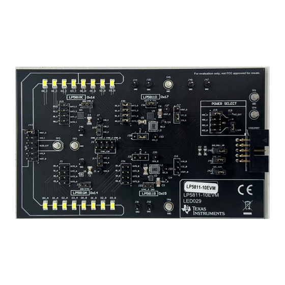
The LP5811/10 evaluation module showcases all
the features of the LP5811 and LP5810 4 channels
RGB LED driver with autonomous control. The
difference between the two devices is dependent on
whether there is a synchronous boost function. The
evaluation module includes four ICs on 1 PCB board:
LP5811WCSP, LP5811WSON, LP5810WCSP, and
LP5810WSON. Select the device by jumper setting
and I2C target address. The graphical user interface
(GUI) is called LP581XEVM-GUI. The GUI is used
to interface with USB to the EVM by the USB2ANY
interface adapter.
Get Started
1. Request the LP5811-10EVM from ti.com.
2. Request the LP5811 and LP5810 data sheet from
ti.com.
SNVU888 – MARCH 2024
Submit Document Feedback
3. Download the LP581XEVM-GUI from ti.com.
4. Download the comprehensive reference design
files.
Features
•
LP5811 synchronous boost 4 channels RGB LED
driver with autonomous control
•
LP5810 4 channels RGB LED driver with
autonomous control
•
I2C input and power supply from USB2ANY
interface adapter
•
LP581XEVM-GUI is used to control the EVM
Applications
•
Portable & wearable
earbuds
•
Gaming & home
RGB mouse,
•
Industrial
Hardware Image
Copyright © 2024 Texas Instruments Incorporated
electronics: e-cigarette,
and charging case
entertainment:
smart
video doorbell
HMI:
EV
charger,
factory automation
LP5811-10 Evaluation Module
Description
speaker,
1
Advertisement
Table of Contents

Related Manuals for Texas Instruments LP5811-10


Summary of Contents for Texas Instruments LP5811-10
- Page 1 1. Request the LP5811-10EVM from ti.com. RGB mouse, video doorbell 2. Request the LP5811 and LP5810 data sheet from • Industrial HMI: charger, factory automation ti.com. Hardware Image SNVU888 – MARCH 2024 LP5811-10 Evaluation Module Submit Document Feedback Copyright © 2024 Texas Instruments Incorporated...
-
Page 2: Kit Contents
This user’s guide describes the characteristics, setup, and usage of the LP5811/LP5810 evaluation module (EVM). The LP5811-10EVM helps the user evaluate the features of the Texas Instruments LP5811 synchronous boost 4 channels RGB LED driver and LP5810 4 channels RGB LED driver, which integrate autonomous control. - Page 3 0.5 V - 5.5 V VOUT LED0 White LED OUT0 10 uF 4.7k 4.7k ¡ LED1 OUT1 LP5811 LED2 OUT2 LED3 SYNC OUT3 Figure 1-3. LP5811 Simplified Schematic SNVU888 – MARCH 2024 LP5811-10 Evaluation Module Submit Document Feedback Copyright © 2024 Texas Instruments Incorporated...
-
Page 4: Jumper Information
Vin is provided by 3.3V from USB2ANY(Don't need external power supply). • Synchronous boost is enabled. • I2C target address is set to 0x17. LP5811-10 Evaluation Module SNVU888 – MARCH 2024 Submit Document Feedback Copyright © 2024 Texas Instruments Incorporated... - Page 5 I2C_SCL/SDA: I2C signal, connected to all devices on the board. SCL/SDA_U2A: I2C signal from USB2ANY interface adapter. 3V3_U2A: Power supply from USB2ANY interface adapter. SNVU888 – MARCH 2024 LP5811-10 Evaluation Module Submit Document Feedback Copyright © 2024 Texas Instruments Incorporated...
- Page 6 The LED supply voltage VLED can be provided by both LED driver power supply(VOUT_B/D, VIN_A/C) and external power supply (VLED_EXT). Table 2-7. SYNC Signal Connection Jumper Name Left Pin Right Pin J2/J8 SYNCA/C J23/J36 SYNCB/D LP5811-10 Evaluation Module SNVU888 – MARCH 2024 Submit Document Feedback Copyright © 2024 Texas Instruments Incorporated...
-
Page 7: Power Supply
4. Plug the USB cable into the USB port on the computer. See the external power supply connection in Figure 2-3. Figure 2-3. External Power Supply SNVU888 – MARCH 2024 LP5811-10 Evaluation Module Submit Document Feedback Copyright © 2024 Texas Instruments Incorporated... -
Page 8: Gui Installation
After the Gallery page, click the download button to install the offline version to the user's computer. See Figure 3-1. Figure 3-1. Gallery Page Follow the setup wizard to install the LP581XEVM-GUI successfully. See Figure 3-2. Figure 3-2. Setup Wizard LP5811-10 Evaluation Module SNVU888 – MARCH 2024 Submit Document Feedback Copyright © 2024 Texas Instruments Incorporated... - Page 9 1. Unplug the USB cable (do not click the UPDATE button). 2. Press the BSL button inside USB2ANY, then plug in the USB cable. 3. Click UPDATE button. SNVU888 – MARCH 2024 LP5811-10 Evaluation Module Submit Document Feedback Copyright © 2024 Texas Instruments Incorporated...
- Page 10 After clicking EXPLORE button, the GUI helps navigate users to the Hardware Set-up page. Click FINISH button when the hardware has been set properly. See Figure 3-6. Figure 3-5. Start Page Figure 3-6. Hardware Setup Page LP5811-10 Evaluation Module SNVU888 – MARCH 2024 Submit Document Feedback Copyright © 2024 Texas Instruments Incorporated...
- Page 11 4. Mode Selection: This part includes LED enable/disable, LED operation mode (manual/auto), PWM dimming scale (linear/exponential), PWM phase align (forward/middle/backward). 5. Device Configuration: Click this button to navigate to the Device configuration page. See Figure 3-9. SNVU888 – MARCH 2024 LP5811-10 Evaluation Module Submit Document Feedback Copyright © 2024 Texas Instruments Incorporated...
- Page 12 Figure 3-8. Mode Select Page Figure 3-9. Device Configuration Page After all the device configurations have been configured, click NEXT button to navigate to Manual Mode Configuration page. LP5811-10 Evaluation Module SNVU888 – MARCH 2024 Submit Document Feedback Copyright © 2024 Texas Instruments Incorporated...
- Page 13 All the parameters in the animation engine related register have random value when power up the device, so configure all the parameters before running the animation. Figure 3-12 shows the Auto Mode Configuration page. SNVU888 – MARCH 2024 LP5811-10 Evaluation Module Submit Document Feedback Copyright © 2024 Texas Instruments Incorporated...
- Page 14 Figure 3-12. Auto Mode Configuration Page Users can preview the LED animation pattern by enabling the Preview Mode and click the SIMULATE button. Figure 3-13. Figure 3-13. Preview Mode LP5811-10 Evaluation Module SNVU888 – MARCH 2024 Submit Document Feedback Copyright © 2024 Texas Instruments Incorporated...
-
Page 15: Fault Detection
To have precise detection results, the PWM must be set above 25. Figure 3-15. LED Fault Report SNVU888 – MARCH 2024 LP5811-10 Evaluation Module Submit Document Feedback Copyright © 2024 Texas Instruments Incorporated... - Page 16 Hardware Design Files www.ti.com 4 Hardware Design Files 4.1 Schematics Figure 4-1 shows the schematic of LED driver module. Figure 4-1. Schematic of LED Driver Module LP5811-10 Evaluation Module SNVU888 – MARCH 2024 Submit Document Feedback Copyright © 2024 Texas Instruments Incorporated...
- Page 17 Hardware Design Files Figure 4-2 shows the schematic of LED load module. Figure 4-2. Schematic of LED Load Module SNVU888 – MARCH 2024 LP5811-10 Evaluation Module Submit Document Feedback Copyright © 2024 Texas Instruments Incorporated...
- Page 18 Hardware Design Files www.ti.com Figure 4-3 shows the schematic of USB2ANY and GND connector. Figure 4-3. Schematic of USB2ANY and GND Connector LP5811-10 Evaluation Module SNVU888 – MARCH 2024 Submit Document Feedback Copyright © 2024 Texas Instruments Incorporated...
- Page 19 Hardware Design Files Figure 4-4 shows the schematic of power supply module. Figure 4-4. Power Supply Module SNVU888 – MARCH 2024 LP5811-10 Evaluation Module Submit Document Feedback Copyright © 2024 Texas Instruments Incorporated...
-
Page 20: Pcb Layouts
Figure 4-5, Figure 4-6, Figure 4-7, and Figure 4-8 detail the LP5811-10EVM layout. Figure 4-5. LP5811-10EVM (Top Layer) Figure 4-6. LP5811-10EVM Signal (Layer 1) LP5811-10 Evaluation Module SNVU888 – MARCH 2024 Submit Document Feedback Copyright © 2024 Texas Instruments Incorporated... - Page 21 Hardware Design Files Figure 4-7. LP5811-10EVM Signal (Layer 2) Figure 4-8. LP5811-10EVM (Bottom Layer) SNVU888 – MARCH 2024 LP5811-10 Evaluation Module Submit Document Feedback Copyright © 2024 Texas Instruments Incorporated...
-
Page 22: Bill Of Materials (Bom)
9-DSBGA -40 to 85 Texas Instruments Synchronous boost 4-channel RGBW LED LP5811BYBHR driver with I2C and auto animation control 12- DSBGA -40 to 85 LP5811-10 Evaluation Module SNVU888 – MARCH 2024 Submit Document Feedback Copyright © 2024 Texas Instruments Incorporated... -
Page 23: Additional Information
USB2ANY Header(shrouded), 2.54mm, 5x2, Gold, R/A, Sullins Connector SBH11-PBPC-D05-RA-BK Solutions 5 Additional Information 5.1 Trademarks All trademarks are the property of their respective owners. SNVU888 – MARCH 2024 LP5811-10 Evaluation Module Submit Document Feedback Copyright © 2024 Texas Instruments Incorporated... - Page 24 STANDARD TERMS FOR EVALUATION MODULES Delivery: TI delivers TI evaluation boards, kits, or modules, including any accompanying demonstration software, components, and/or documentation which may be provided together or separately (collectively, an “EVM” or “EVMs”) to the User (“User”) in accordance with the terms set forth herein.
- Page 25 www.ti.com Regulatory Notices: 3.1 United States 3.1.1 Notice applicable to EVMs not FCC-Approved: FCC NOTICE: This kit is designed to allow product developers to evaluate electronic components, circuitry, or software associated with the kit to determine whether to incorporate such items in a finished product and software developers to write software applications for use with the end product.
- Page 26 www.ti.com Concernant les EVMs avec antennes détachables Conformément à la réglementation d'Industrie Canada, le présent émetteur radio peut fonctionner avec une antenne d'un type et d'un gain maximal (ou inférieur) approuvé pour l'émetteur par Industrie Canada. Dans le but de réduire les risques de brouillage radioélectrique à...
- Page 27 www.ti.com EVM Use Restrictions and Warnings: 4.1 EVMS ARE NOT FOR USE IN FUNCTIONAL SAFETY AND/OR SAFETY CRITICAL EVALUATIONS, INCLUDING BUT NOT LIMITED TO EVALUATIONS OF LIFE SUPPORT APPLICATIONS. 4.2 User must read and apply the user guide and other available documentation provided by TI regarding the EVM prior to handling or using the EVM, including without limitation any warning or restriction notices.
- Page 28 Notwithstanding the foregoing, any judgment may be enforced in any United States or foreign court, and TI may seek injunctive relief in any United States or foreign court. Mailing Address: Texas Instruments, Post Office Box 655303, Dallas, Texas 75265 Copyright © 2023, Texas Instruments Incorporated...
-
Page 29: Important Notice
TI products. TI’s provision of these resources does not expand or otherwise alter TI’s applicable warranties or warranty disclaimers for TI products. TI objects to and rejects any additional or different terms you may have proposed. IMPORTANT NOTICE Mailing Address: Texas Instruments, Post Office Box 655303, Dallas, Texas 75265 Copyright © 2024, Texas Instruments Incorporated...
Need help?
Do you have a question about the LP5811-10 and is the answer not in the manual?
Questions and answers