Table of Contents
Advertisement
Quick Links
www.ti.com
EVM User's Guide: LP5861TEVM
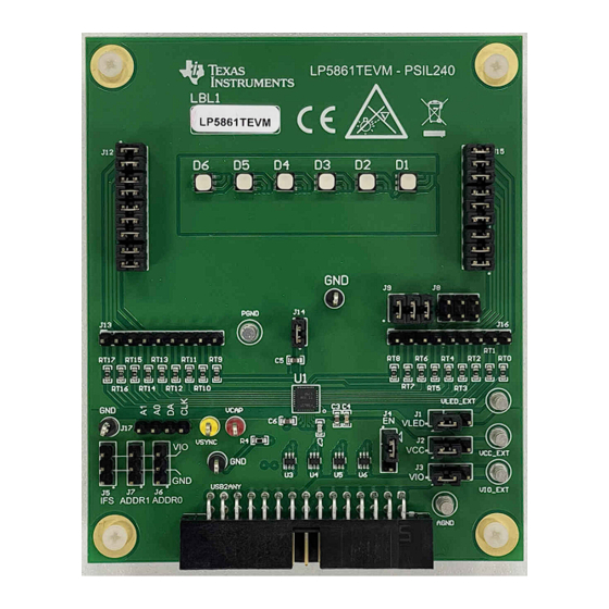
LP5861T Evaluation Module
Description
The LP5861T Evaluation Module showcases all the
features of the LP5861T LED matrix driver. The
graphical user interface or GUI called LP586x GUI
is used to interface with USB2ANY to the EVM. The
EVM has SPI and I2C inputs through the USB2ANY
interface adapter.
Get Started
1. Order the EVM on ti.com
2. Request the LP5861T data sheet
3. Download the LP586xGUI from ti.com
4. Request the EVM design files
SNVU870 – JUNE 2023
Submit Document Feedback
Features
•
LP5861T 18-channel high-current LED driver with
8-Bit analog and 8-Bit or 16-Bit PWM dimming
•
SPI, I2C, Vsync, IFS, EN signal input from
USB2ANY interface adapter
•
LP586x GUI is used to control the EVM
Applications
•
Major and smart home appliance
•
IR module for video surveillance and IP camera
•
Laser diode in optical module
•
Smart speaker
Copyright © 2023 Texas Instruments Incorporated
Description
LP5861T Evaluation Module
1
Advertisement
Table of Contents

Related Manuals for Texas Instruments LP5861T


Summary of Contents for Texas Instruments LP5861T
- Page 1 Features The LP5861T Evaluation Module showcases all the • LP5861T 18-channel high-current LED driver with features of the LP5861T LED matrix driver. The 8-Bit analog and 8-Bit or 16-Bit PWM dimming graphical user interface or GUI called LP586x GUI •...
-
Page 2: Kit Contents
• USB2ANY interface adapter with ribbon cables and USB cable Figure 1-1. LP5861TEVM Kit Full functions for the LP5861T, the performance with RGB LEDs, and some simple animation effects can be easily verified through this kit. 1.3 Specification The evaluation module provides several inputs. The inputs are I2C, SPI, Vsync, EN, IFS signal input and power supplies for VCC, VLED. -
Page 3: Hardware Setup
Hardware 2 Hardware This following chapters describe how to set up the LP5861TEVM properly. Items from the following list are required to begin evaluating the LP5861T: • Computer • LP5861TEVM • USB2ANY interface adapter 2.1 Hardware Setup In the default jumper setting, the board can be evaluated by USB power directly and does not need an external power supply. - Page 4 2-3) and connect the switching jumper (J1) to another side. 3. Plug the USB cable into the USB port on the computer. Figure 2-3. Key External Connectors LP5861T Evaluation Module SNVU870 – JUNE 2023 Submit Document Feedback Copyright © 2023 Texas Instruments Incorporated...
-
Page 5: Software Setup
Click the connection button to connect or disconnect the LP5861TEVM with the GUI. Connection button Connection status Log panel Figure 3-2. Status Bar SNVU870 – JUNE 2023 LP5861T Evaluation Module Submit Document Feedback Copyright © 2023 Texas Instruments Incorporated... - Page 6 UPDATE button); 2) Pressing the BSL button inside USB2ANY, then plug in the USB cable; 3) Clicking UPDATE button, see Figure 3-3. Figure 3-4. Firmware Update LP5861T Evaluation Module SNVU870 – JUNE 2023 Submit Document Feedback Copyright © 2023 Texas Instruments Incorporated...
- Page 7 Different device variants in the LP586x family are selected from the Start Page. To begin evaluation, because we only have LP5861 option in the start page, considering LP5861 and LP5861T have same register configuration, so select the LP5861 tab then click the EXPLORE button to begin evaluation, see Figure 3-3.
-
Page 8: Device Configuration
3-6. Maximum current (MC) is set here. Please note: if LP5861T is under test, then the Global Maximum Current setting is: 7.5mA, 12.5mA, 25 mA, 37.5mA, 50 mA, 75 mA, 100 mA, 125 mA related to each button (000 - 111 for bit3 - bit1 in Dev_config3 register) under Global Maximum Current setting. - Page 9 3-7. Brightness is used to adjust the PWM for all 3 dots in one RGB LED. For some high requirement applications, dot current can adjust white balance for every RGB LED. Figure 3-9. Custom Setting SNVU870 – JUNE 2023 LP5861T Evaluation Module Submit Document Feedback Copyright © 2023 Texas Instruments Incorporated...
- Page 10 GROUP tab where every LED dot can be configured to three groups arbitrarily, while the PWM for the same group can be changed synchronously. Figure 3-10. Global Setting Figure 3-11. Group Setting LP5861T Evaluation Module SNVU870 – JUNE 2023 Submit Document Feedback Copyright © 2023 Texas Instruments Incorporated...
-
Page 11: Fault Detection
Fault Detection The LP5861T continually detects the status for every LED dot. Once an open or short failure is detected, the fault status is also be monitored on the GUI. Clicking the warning bar near an abnormal LED shows the fault... - Page 12 Play button to display the animation. Speed and color are set at the right side. Before evaluating the patterns, first reset the LP5861TEVM board if some values are already set in LED control page. Figure 3-14. Pattern Page LP5861T Evaluation Module SNVU870 – JUNE 2023 Submit Document Feedback Copyright © 2023 Texas Instruments Incorporated...
- Page 13 When Auto Read is off, click Read Register to read the value from the selected register, and click Read all Registers to read all registers manually. Figure 3-15. Register Map Page SNVU870 – JUNE 2023 LP5861T Evaluation Module Submit Document Feedback Copyright © 2023 Texas Instruments Incorporated...
- Page 14 Hardware Design Files www.ti.com 4 Hardware Design Files The Schematic, PCB Layouts, and Bill of Materials of the LP5861T EVM board design are included in this section. 4.1 Schematic Figure 4-5 shows the LP5861TEVM schematic. Figure 4-1. LP5861TEVM Schematic LP5861T Evaluation Module SNVU870 –...
-
Page 15: Pcb Layouts
LP5861TEVM layout images. Figure 4-2. LP5861TEVM Top Layer Figure 4-3. LP5861TEVM Signal Layer 1 Figure 4-4. LP5861TEVM Bottom Layer Figure 4-5. LP5861TEVM Signal Layer 2 SNVU870 – JUNE 2023 LP5861T Evaluation Module Submit Document Feedback Copyright © 2023 Texas Instruments Incorporated... - Page 16 Test Point, Multipurpose, Red, TH Keystone 5010 VSYNC Test Point, Multipurpose, Yellow, TH Keystone 5014 5 Additional Information Trademarks All trademarks are the property of their respective owners. LP5861T Evaluation Module SNVU870 – JUNE 2023 Submit Document Feedback Copyright © 2023 Texas Instruments Incorporated...
- Page 17 STANDARD TERMS FOR EVALUATION MODULES Delivery: TI delivers TI evaluation boards, kits, or modules, including any accompanying demonstration software, components, and/or documentation which may be provided together or separately (collectively, an “EVM” or “EVMs”) to the User (“User”) in accordance with the terms set forth herein.
- Page 18 www.ti.com Regulatory Notices: 3.1 United States 3.1.1 Notice applicable to EVMs not FCC-Approved: FCC NOTICE: This kit is designed to allow product developers to evaluate electronic components, circuitry, or software associated with the kit to determine whether to incorporate such items in a finished product and software developers to write software applications for use with the end product.
- Page 19 www.ti.com Concernant les EVMs avec antennes détachables Conformément à la réglementation d'Industrie Canada, le présent émetteur radio peut fonctionner avec une antenne d'un type et d'un gain maximal (ou inférieur) approuvé pour l'émetteur par Industrie Canada. Dans le but de réduire les risques de brouillage radioélectrique à...
- Page 20 www.ti.com EVM Use Restrictions and Warnings: 4.1 EVMS ARE NOT FOR USE IN FUNCTIONAL SAFETY AND/OR SAFETY CRITICAL EVALUATIONS, INCLUDING BUT NOT LIMITED TO EVALUATIONS OF LIFE SUPPORT APPLICATIONS. 4.2 User must read and apply the user guide and other available documentation provided by TI regarding the EVM prior to handling or using the EVM, including without limitation any warning or restriction notices.
- Page 21 Notwithstanding the foregoing, any judgment may be enforced in any United States or foreign court, and TI may seek injunctive relief in any United States or foreign court. Mailing Address: Texas Instruments, Post Office Box 655303, Dallas, Texas 75265 Copyright © 2023, Texas Instruments Incorporated...
-
Page 22: Important Notice
TI products. TI’s provision of these resources does not expand or otherwise alter TI’s applicable warranties or warranty disclaimers for TI products. TI objects to and rejects any additional or different terms you may have proposed. IMPORTANT NOTICE Mailing Address: Texas Instruments, Post Office Box 655303, Dallas, Texas 75265 Copyright © 2023, Texas Instruments Incorporated...
Need help?
Do you have a question about the LP5861T and is the answer not in the manual?
Questions and answers