Advertisement
www.ti.com
EVM User's Guide: LP5891Q1EVM
LP5891-Q1 48 × 16 Common Cathode Matrix LED Display
Driver Evaluation Module
Description
The LP5891-Q1 evaluation module (EVM) is used to
evaluate the characteristics, operation, and usage for
matrix LED display driver LP5891-Q1. The LP5891-
Q1 is a highly integrated, common cathode matrix
LED display driver with 48 constant current sources
and 16 scanning FETs. The LP5891-Q1 is AEC-Q100-
qualified for automotive applications.
Features
•
48 current source channels from 0.2mA to 20mA
•
16 scan line switches with 190mΩ R
SNVU836A – MARCH 2023 – REVISED APRIL 2024
Submit Document Feedback
•
Ultra-low power consumption
•
High-speed and low electromagnetic interference
(EMI) continuous clock series interface (CCSI)
Applications
•
Automotive free-form interactive signal display
(FISD)
•
Automotive ambient lighting
•
Automotive head light and rear light with ultra-high-
density pixels
•
Automotive mini and micro-LED panels
•
Automotive local dimming backlight
DS(ON)
LP5891-Q1 48 × 16 Common Cathode Matrix LED Display Driver Evaluation
Copyright © 2024 Texas Instruments Incorporated
Description
1
Module
Advertisement
Table of Contents

Related Manuals for Texas Instruments LP5891Q1EVM


Summary of Contents for Texas Instruments LP5891Q1EVM
- Page 1 Automotive local dimming backlight • 16 scan line switches with 190mΩ R DS(ON) SNVU836A – MARCH 2023 – REVISED APRIL 2024 LP5891-Q1 48 × 16 Common Cathode Matrix LED Display Driver Evaluation Submit Document Feedback Module Copyright © 2024 Texas Instruments Incorporated...
-
Page 2: Kit Contents
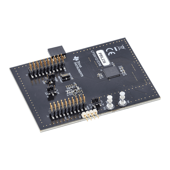
LP5891-Q1 48 × 16 Common Cathode Matrix LED Display Driver Evaluation SNVU836A – MARCH 2023 – REVISED APRIL 2024 Module Submit Document Feedback Copyright © 2024 Texas Instruments Incorporated... - Page 3 Hardware 2 Hardware 2.1 Function Descriptions This section describes the connectors, jumpers, and switches on the LP5891Q1EVM board. Figure 2-1 shows the image of the driver IC side of the LP5891Q1EVM board. Figure 2-2 shows the image of the LED side of the LP5891Q1EVM board.
- Page 4 MCU. The LP5891Q1EVM is designed with connectors, jumpers, and switches to support device-to-device connection, device-to-host connection, and flexible power supply scheme. In addition, there are four switches on the LED side of the LP5891Q1EVM board that enables the evaluation of LED open and short detection and removal functions of the LP5891-Q1.
-
Page 5: Test Setup
The LP5891Q1EVM can be powered either by the TMS320F280039C LaunchPad with the USB power (when the current consumption is low) or an external power supply (the LP5891Q1EVM and the TMS320F280039C LaunchPad are powered separately). Single LP5891Q1EVM can be quickly set up and tested by following these steps: 1. - Page 6 1. Download the code to the TMS320F280039C LaunchPad with TI Code Composer Studio software. 2. For the first LP5891Q1EVM, put the J5 jumper on TP1 5V and EX 5V. Then put the J6 jumper on EX5V and the middle. Set the switch S1 towards SOUT1TO2. These setups are marked with red boxes on the First...
- Page 7 Software 3. For the second LP5891Q1EVM, put the J5 jumper on J3 5V and EX 5V. Then put the J6 jumper on EX5V and the middle. Set the switch S1 towards SOUTHOST. These setups are marked with red boxes on the...
- Page 8 Hardware Design Files www.ti.com 4 Hardware Design Files 4.1 Schematic The schematic of the EVM is shown below. Designator LP5891Q1EVM_Driversch.SchDoc Designator LP5891Q1EVM_Hardware.SchDoc LP5891Q1EVM_LEDsch.SchDoc LP5891Q1EVM_LEDsch_2.SchDoc Figure 4-1. LP5891Q1EVM Schematic (1 of 4) Line0 Line1 Line2 Line3 Line4 10uF 1µF Line5 AGND Line6...
- Page 9 G31C CAS-120TA CAS-120TA CAS-120TA CAS-120TA Figure 4-3. LP5891Q1EVM Schematic (3 of 4) SNVU836A – MARCH 2023 – REVISED APRIL 2024 LP5891-Q1 48 × 16 Common Cathode Matrix LED Display Driver Evaluation Submit Document Feedback Module Copyright © 2024 Texas Instruments Incorporated...
- Page 10 EAST1616RGBA8 EAST1616RGBA8 EAST1616RGBA8 EAST1616RGBA8 Line15 Figure 4-4. LP5891Q1EVM Schematic (4 of 4) LP5891-Q1 48 × 16 Common Cathode Matrix LED Display Driver Evaluation SNVU836A – MARCH 2023 – REVISED APRIL 2024 Module Submit Document Feedback Copyright © 2024 Texas Instruments Incorporated...
-
Page 11: Pcb Layout
4.2 PCB Layout The PCB layout of the EVM is shown below. Figure 4-5. LP5891Q1EVM Top Layer Figure 4-6. LP5891Q1EVM Signal Layer 1 Figure 4-7. LP5891Q1EVM Signal Layer 2 Figure 4-8. LP5891Q1EVM Bottom Layer SNVU836A – MARCH 2023 – REVISED APRIL 2024 LP5891-Q1 48 ×... -
Page 12: Bill Of Materials
Hardware Design Files www.ti.com 4.3 Bill of Materials Table 4-1 lists the bill of materials for LP5891Q1EVM. Table 4-1. Bill of Materials Designator Qty. Description Part Number Manufacturer CAP, CERM, 1µF, 10V,±20%, X5R, C1, C3, C4 CC0402MRX5R6BB105 Yageo America 0402 CAP, CERM, 10uF, 10V, ±10%, X7T,... -
Page 13: Revision History
• LP5891-Q1 data sheet, product information and support | TI.com • LP5891Q1EVM Evaluation board | TI.com • [FAQ] How to master LP589x / TLC698x devices with LED display applications within five minutes? - Power management forum - Power management - TI E2E support forums 5.2 Trademarks... - Page 14 STANDARD TERMS FOR EVALUATION MODULES Delivery: TI delivers TI evaluation boards, kits, or modules, including any accompanying demonstration software, components, and/or documentation which may be provided together or separately (collectively, an “EVM” or “EVMs”) to the User (“User”) in accordance with the terms set forth herein.
- Page 15 www.ti.com Regulatory Notices: 3.1 United States 3.1.1 Notice applicable to EVMs not FCC-Approved: FCC NOTICE: This kit is designed to allow product developers to evaluate electronic components, circuitry, or software associated with the kit to determine whether to incorporate such items in a finished product and software developers to write software applications for use with the end product.
- Page 16 www.ti.com Concernant les EVMs avec antennes détachables Conformément à la réglementation d'Industrie Canada, le présent émetteur radio peut fonctionner avec une antenne d'un type et d'un gain maximal (ou inférieur) approuvé pour l'émetteur par Industrie Canada. Dans le but de réduire les risques de brouillage radioélectrique à...
- Page 17 www.ti.com EVM Use Restrictions and Warnings: 4.1 EVMS ARE NOT FOR USE IN FUNCTIONAL SAFETY AND/OR SAFETY CRITICAL EVALUATIONS, INCLUDING BUT NOT LIMITED TO EVALUATIONS OF LIFE SUPPORT APPLICATIONS. 4.2 User must read and apply the user guide and other available documentation provided by TI regarding the EVM prior to handling or using the EVM, including without limitation any warning or restriction notices.
- Page 18 Notwithstanding the foregoing, any judgment may be enforced in any United States or foreign court, and TI may seek injunctive relief in any United States or foreign court. Mailing Address: Texas Instruments, Post Office Box 655303, Dallas, Texas 75265 Copyright © 2023, Texas Instruments Incorporated...
- Page 19 TI products. TI’s provision of these resources does not expand or otherwise alter TI’s applicable warranties or warranty disclaimers for TI products. TI objects to and rejects any additional or different terms you may have proposed. IMPORTANT NOTICE Mailing Address: Texas Instruments, Post Office Box 655303, Dallas, Texas 75265 Copyright © 2024, Texas Instruments Incorporated...
Need help?
Do you have a question about the LP5891Q1EVM and is the answer not in the manual?
Questions and answers