Table of Contents
Advertisement
Quick Links
www.ti.com
EVM User's Guide: LP5813EVM LP5812EVM
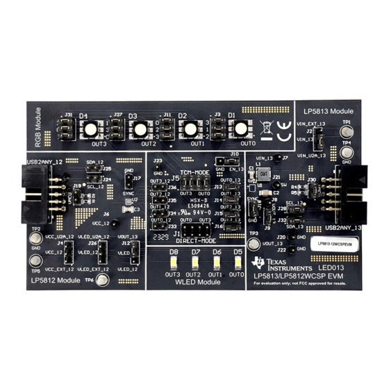
LP5813-12 Evaluation Module
Description
The LP5813/12 Evaluation Module showcases all the
features of the LP5813 and LP5812 4 × 3 matrix RGB
LED driver with autonomous control. The difference
between 2 devices is with or without synchronous
boost function. Both LP5813 and LP5812 are placed
on 1 board, please select the device which is needed
to be evaluated by USB2ANY connector and jumper
setting. And please select the right EVM version
according to different package (WSON/WCSP). The
graphical user interface or GUI called LP581x GUI
is used to interface with USB to the EVM by the
USB2ANY interface adapter.
Get Started
1. Request the LP5813-12 WCSP/WSON EVM from
ti.com
according to the device package.
2. Request the LP5813 and LP5812 data sheet from
ti.com.
SNVU868 – SEPTEMBER 2023
Submit Document Feedback
3. Download the LP581xGUI from ti.com.
4. Download the comprehensive reference design
files.
Features
•
LP5813 Synchronous Boost 4 × 3 Matrix RGB LED
driver with autonomous control
•
LP5812 4 × 3 Matrix RGB LED driver with
autonomous control
•
I2C input and power supply from USB2ANY
interface adapter
•
LP581x GUI is used to control the EVM
Applications
•
Portable & wearable
Earbud & Charging case
•
Gaming & home
RGB mouse, Video doorbell
•
Industrial
Hardware Image
Copyright © 2023 Texas Instruments Incorporated
electronics: E-Cigarette,
entertainment: Smart speaker,
HMI: EV charger, Factory automation
LP5813-12 Evaluation Module
Description
1
Advertisement
Table of Contents

Related Manuals for Texas Instruments LP5813EVM


Summary of Contents for Texas Instruments LP5813EVM
- Page 1 Description EVM User's Guide: LP5813EVM LP5812EVM LP5813-12 Evaluation Module 3. Download the LP581xGUI from ti.com. Description 4. Download the comprehensive reference design The LP5813/12 Evaluation Module showcases all the files. features of the LP5813 and LP5812 4 × 3 matrix RGB Features LED driver with autonomous control.
-
Page 2: Kit Contents
This user’s guide describes the characteristics, setup, and usage of the LP5813/LP5812 evaluation module (EVM). The LP5813/LP5812EVM helps the user evaluate the features of the Texas Instruments LP5813 synchronous boost 4 × 3 matrix RGB LED driver and LP5812 4 × 3 matrix RGB LED driver, which integrate autonomous control. - Page 3 1 uH Blue LED 0.5 V - 5.5 V VOUT OUT0 10 uF 4.7kΩ 4.7kΩ OUT1 LP5813 OUT2 SYNC OUT3 Figure 1-2. LP5813 Simplified Schematic SNVU868 – SEPTEMBER 2023 LP5813-12 Evaluation Module Submit Document Feedback Copyright © 2023 Texas Instruments Incorporated...
-
Page 4: Jumper Information
Vin is provided by 3.3V from USB2ANY(Don't need external power supply). • Synchronous boost is enabled. • 4-SCAN TCM mode (Drive 12 LED dots with 4 outputs). LP5813-12 Evaluation Module SNVU868 – SEPTEMBER 2023 Submit Document Feedback Copyright © 2023 Texas Instruments Incorporated... - Page 5 LP5813 in Direct mode and enable boost function without external power supply. Figure 2-3. LP5813 Direct Mode and Enable Boost without External Power Supply SNVU868 – SEPTEMBER 2023 LP5813-12 Evaluation Module Submit Document Feedback Copyright © 2023 Texas Instruments Incorporated...
- Page 6 Figure 2-5 shows the jumper setting for LP5812 in TCM mode without external power supply. Figure 2-5. LP5812 4-SCAN TCM Mode without External Power Supply LP5813-12 Evaluation Module SNVU868 – SEPTEMBER 2023 Submit Document Feedback Copyright © 2023 Texas Instruments Incorporated...
-
Page 7: Power Supply
3. If the user wants to evaluate LP5813 but disable the boost function, then please provide power supply from Vout instead of VIN. 4. Plug the USB cable into the USB port on the computer. SNVU868 – SEPTEMBER 2023 LP5813-12 Evaluation Module Submit Document Feedback Copyright © 2023 Texas Instruments Incorporated... - Page 8 Software www.ti.com 3 Software 3.1 Software Description LP581xGUI information will be updated after RTM. LP5813-12 Evaluation Module SNVU868 – SEPTEMBER 2023 Submit Document Feedback Copyright © 2023 Texas Instruments Incorporated...
- Page 9 Figure 4-1 shows the schematic of LED driver module. Figure 4-1. Schematic of LED Driver Module Figure 4-2 shows the schematic of LED Load module. SNVU868 – SEPTEMBER 2023 LP5813-12 Evaluation Module Submit Document Feedback Copyright © 2023 Texas Instruments Incorporated...
- Page 10 Hardware Design Files www.ti.com Figure 4-2. Schematic of LED Load Module Figure 4-3 shows the schematic of USB2ANY connector. LP5813-12 Evaluation Module SNVU868 – SEPTEMBER 2023 Submit Document Feedback Copyright © 2023 Texas Instruments Incorporated...
- Page 11 Hardware Design Files Figure 4-3. Schematic of USB2ANY Connector SNVU868 – SEPTEMBER 2023 LP5813-12 Evaluation Module Submit Document Feedback Copyright © 2023 Texas Instruments Incorporated...
-
Page 12: Pcb Layouts
Hardware Design Files www.ti.com 4.2 PCB Layouts Figure 4-4 Figure 4-5 demonstrate the LP5813-12WCSPEVM layout images. Figure 4-4. LP5813-12WCSPEVM Top Layer Figure 4-5. LP5813-12WCSPEVM Bottom Layer LP5813-12 Evaluation Module SNVU868 – SEPTEMBER 2023 Submit Document Feedback Copyright © 2023 Texas Instruments Incorporated... -
Page 13: Additional Information
Header(shrouded), 2.54mm, 15x2, Gold with SBH11-PBPC-D05-RA-BK Tin tail, R/A, TH USB2ANY_13 Solutions 5 Additional Information 5.1 Trademarks All trademarks are the property of their respective owners. SNVU868 – SEPTEMBER 2023 LP5813-12 Evaluation Module Submit Document Feedback Copyright © 2023 Texas Instruments Incorporated... - Page 14 STANDARD TERMS FOR EVALUATION MODULES Delivery: TI delivers TI evaluation boards, kits, or modules, including any accompanying demonstration software, components, and/or documentation which may be provided together or separately (collectively, an “EVM” or “EVMs”) to the User (“User”) in accordance with the terms set forth herein.
- Page 15 www.ti.com Regulatory Notices: 3.1 United States 3.1.1 Notice applicable to EVMs not FCC-Approved: FCC NOTICE: This kit is designed to allow product developers to evaluate electronic components, circuitry, or software associated with the kit to determine whether to incorporate such items in a finished product and software developers to write software applications for use with the end product.
- Page 16 www.ti.com Concernant les EVMs avec antennes détachables Conformément à la réglementation d'Industrie Canada, le présent émetteur radio peut fonctionner avec une antenne d'un type et d'un gain maximal (ou inférieur) approuvé pour l'émetteur par Industrie Canada. Dans le but de réduire les risques de brouillage radioélectrique à...
- Page 17 www.ti.com EVM Use Restrictions and Warnings: 4.1 EVMS ARE NOT FOR USE IN FUNCTIONAL SAFETY AND/OR SAFETY CRITICAL EVALUATIONS, INCLUDING BUT NOT LIMITED TO EVALUATIONS OF LIFE SUPPORT APPLICATIONS. 4.2 User must read and apply the user guide and other available documentation provided by TI regarding the EVM prior to handling or using the EVM, including without limitation any warning or restriction notices.
- Page 18 Notwithstanding the foregoing, any judgment may be enforced in any United States or foreign court, and TI may seek injunctive relief in any United States or foreign court. Mailing Address: Texas Instruments, Post Office Box 655303, Dallas, Texas 75265 Copyright © 2023, Texas Instruments Incorporated...
-
Page 19: Important Notice
TI products. TI’s provision of these resources does not expand or otherwise alter TI’s applicable warranties or warranty disclaimers for TI products. TI objects to and rejects any additional or different terms you may have proposed. IMPORTANT NOTICE Mailing Address: Texas Instruments, Post Office Box 655303, Dallas, Texas 75265 Copyright © 2023, Texas Instruments Incorporated...
Need help?
Do you have a question about the LP5813EVM and is the answer not in the manual?
Questions and answers