Table of Contents
Advertisement
Quick Links
www.ti.com
User's Guide
LP5860 Evaluation Module
This user's guide describes the characteristics, setup, and usage of the LP5860 evaluation module (EVM).
The LP5860EVM helps the user evaluate the features of the Texas Instruments LP5860 LED matrix driver,
which integrates 11 scan switches and 18 constant current sinks. This user's guide includes hardware setup
instructions, graphical user interface (GUI) instructions, printed-circuit board (PCB) layout drawings, a schematic
diagram, and a bill of materials,.
1
Introduction.............................................................................................................................................................................2
2.1 Hardware Setup.................................................................................................................................................................
Setup...................................................................................................................................................................4
3 Graphical User Interface (GUI) Guidance.............................................................................................................................
3.1 Start Page..........................................................................................................................................................................
3.2 Home Page........................................................................................................................................................................
3.3 LED Control Page..............................................................................................................................................................
3.4 Pattern Page....................................................................................................................................................................
Page...........................................................................................................................................................11
4 LP5860EVM Design Resources...........................................................................................................................................
4.1 LP5860EVM Layout.........................................................................................................................................................
4.2 LP5860EVM Schematic...................................................................................................................................................
BOM............................................................................................................................................................15
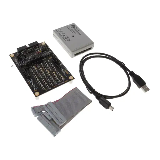
Figure 1-1. LP5860EVM Kit.........................................................................................................................................................
Connection................................................................................................................................................3
Connectors...........................................................................................................................................4
Installation..........................................................................................................................................................4
Bar..................................................................................................................................................................5
Update.......................................................................................................................................................5
Figure 3-3. Start Page.................................................................................................................................................................
Figure 3-4. Home Page...............................................................................................................................................................
Figure 3-5. LED Control Page and Test Procedure.....................................................................................................................
Figure 3-6. Device Configuration.................................................................................................................................................
Setting..........................................................................................................................................................8
Setting............................................................................................................................................................8
Figure 3-9. Group Setting............................................................................................................................................................
Figure 3-10. Single Fault Alarm...................................................................................................................................................
Summary..............................................................................................................................................10
Figure 3-12. Pattern Page.........................................................................................................................................................
Figure 3-13. Register Map Page................................................................................................................................................
Figure 4-1. LP5860EVM Top Layer...........................................................................................................................................
Figure 4-2. LP5860EVM Signal Layer 1....................................................................................................................................
Figure 4-4. LP5860EVM Signal Layer 2....................................................................................................................................
Figure 4-5. LP5860EVM Schematic..........................................................................................................................................
SNVU762 - MAY 2021
Submit Document Feedback
Table of Contents
Preparation.....................................................................................................................................3
List of Figures
Setting..............................................................................................................................................3
Layer......................................................................................................................................13
Copyright © 2021 Texas Instruments Incorporated
ABSTRACT
Table of Contents
3
5
5
6
6
10
12
12
14
2
5
6
7
7
9
9
10
11
12
12
13
14
LP5860 Evaluation Module
1
Advertisement
Table of Contents

Related Manuals for Texas Instruments LP5860


Summary of Contents for Texas Instruments LP5860
-
Page 1: Table Of Contents
This user’s guide describes the characteristics, setup, and usage of the LP5860 evaluation module (EVM). The LP5860EVM helps the user evaluate the features of the Texas Instruments LP5860 LED matrix driver, which integrates 11 scan switches and 18 constant current sinks. This user’s guide includes hardware setup instructions, graphical user interface (GUI) instructions, printed-circuit board (PCB) layout drawings, a schematic diagram, and a bill of materials,. -
Page 2: Introduction
• USB2ANY interface adapter with ribbon cables and USB cable Full functions for the LP5860, the performance with RGB LED matrix, and some simple animation effects can be easily verified through this kit. The LP5860EVM can be converted for testing the LP5868 and LP5866, which are from the same device family, by removing the factory-installed device (U1) and replacing it with the LP5868 or LP5866 counterpart. -
Page 3: Hardware And Software Preparation
Hardware and Software Preparation 2 Hardware and Software Preparation This following chapters describe how to set up the LP5860EVM and GUI properly. Items from the following list are required to begin evaluating the LP5860: • Computer • LP5860EVM kit hardware •... -
Page 4: Software Setup
Download the LP586x GUI installation package from the LP5860 product folder. Follow the setup wizard to install the LP586x GUI successfully, see Figure 2-4. Figure 2-4. GUI Installation LP5860 Evaluation Module SNVU762 – MAY 2021 Submit Document Feedback Copyright © 2021 Texas Instruments Incorporated... -
Page 5: Graphical User Interface (Gui) Guidance
Figure 3-2. Firmware Update 3.1 Start Page Different device variants in the LP586x family are selected from the Start Page. To begin evaluation, select the LP5860 tab then click the EXPLORE button to begin evaluation, see Figure 3-3. Figure 3-3. Start Page SNVU762 –... -
Page 6: Home Page
Figure 3-5. 1. Click the Enable button to enable the LP5860 in the software 2. Select the LED you want to control 3. Set a color for this LED 4. Click the VSync button to active this LED (The default is Mode 3 so the SYNC signal is necessary). -
Page 7: Figure 3-5. Led Control Page And Test Procedure
The Max Scan Lines controls select how many scan lines are active. For more information on the functions for other settings, see the LP5860 11 × 18 LED Matrix Driver with 8-bit Analog and 8-, 16-bit PWM Dimming Data Sheet. -
Page 8: Figure 3-7. Custom Setting
GROUP tab where every LED dot can be configured to 3 groups arbitrarily, while the PWM for the same group can be changed synchronously. Figure 3-8. Global Setting LP5860 Evaluation Module SNVU762 – MAY 2021 Submit Document Feedback Copyright © 2021 Texas Instruments Incorporated... -
Page 9: Figure 3-9. Group Setting
Fault Detection The LP5860 continually detects the status for every LED dot. Once an open or short failure is detected, the fault status is also be monitored on the GUI. Clicking the warning bar near an abnormal LED shows the fault details,... -
Page 10: Pattern Page
Play button to display the animation. Speed and color are set at the right side. Before evaluating the patterns, first reset the LP5860EVM board if some values are already set in LED control page. Figure 3-12. Pattern Page LP5860 Evaluation Module SNVU762 – MAY 2021 Submit Document Feedback Copyright © 2021 Texas Instruments Incorporated... -
Page 11: Register Map Page
When Auto Read is off, click Read Register to read the value from the selected register, and click Read all Registers to read all registers manually. Figure 3-13. Register Map Page SNVU762 – MAY 2021 LP5860 Evaluation Module Submit Document Feedback Copyright © 2021 Texas Instruments Incorporated... -
Page 12: Lp5860Evm Design Resources
LP5860EVM Design Resources www.ti.com 4 LP5860EVM Design Resources The layout, schematic, and bill of materials (BOM) of the LP5860 EVM board design are included in this section. 4.1 LP5860EVM Layout Figure 4-1, Figure 4-2, Figure 4-3, and Figure 4-4 demonstrate the LP5860EVM layout images. -
Page 13: Figure 4-3. Lp5860Evm Bottom Layer
LP5860EVM Design Resources Figure 4-3. LP5860EVM Bottom Layer Figure 4-4. LP5860EVM Signal Layer 2 SNVU762 – MAY 2021 LP5860 Evaluation Module Submit Document Feedback Copyright © 2021 Texas Instruments Incorporated... -
Page 14: Lp5860Evm Schematic
G G G G G G G G G G G G G G G CS0_L CS3_L CS6_L CS9_L CS12_L CS15_L Figure 4-5. LP5860EVM Schematic LP5860 Evaluation Module SNVU762 – MAY 2021 Submit Document Feedback Copyright © 2021 Texas Instruments Incorporated... -
Page 15: Lp5860Evm Bom
USB2ANY Samtec 'TST-115-04-L-D-RA with Tin tail, R/A, TH VCAP Test Point, Multipurpose, Red, TH Keystone 5010 VSYNC Test Point, Multipurpose, Yellow, TH Keystone 5014 SNVU762 – MAY 2021 LP5860 Evaluation Module Submit Document Feedback Copyright © 2021 Texas Instruments Incorporated... - Page 16 STANDARD TERMS FOR EVALUATION MODULES Delivery: TI delivers TI evaluation boards, kits, or modules, including any accompanying demonstration software, components, and/or documentation which may be provided together or separately (collectively, an “EVM” or “EVMs”) to the User (“User”) in accordance with the terms set forth herein.
- Page 17 www.ti.com Regulatory Notices: 3.1 United States 3.1.1 Notice applicable to EVMs not FCC-Approved: FCC NOTICE: This kit is designed to allow product developers to evaluate electronic components, circuitry, or software associated with the kit to determine whether to incorporate such items in a finished product and software developers to write software applications for use with the end product.
- Page 18 www.ti.com Concernant les EVMs avec antennes détachables Conformément à la réglementation d'Industrie Canada, le présent émetteur radio peut fonctionner avec une antenne d'un type et d'un gain maximal (ou inférieur) approuvé pour l'émetteur par Industrie Canada. Dans le but de réduire les risques de brouillage radioélectrique à...
- Page 19 www.ti.com EVM Use Restrictions and Warnings: 4.1 EVMS ARE NOT FOR USE IN FUNCTIONAL SAFETY AND/OR SAFETY CRITICAL EVALUATIONS, INCLUDING BUT NOT LIMITED TO EVALUATIONS OF LIFE SUPPORT APPLICATIONS. 4.2 User must read and apply the user guide and other available documentation provided by TI regarding the EVM prior to handling or using the EVM, including without limitation any warning or restriction notices.
- Page 20 Notwithstanding the foregoing, any judgment may be enforced in any United States or foreign court, and TI may seek injunctive relief in any United States or foreign court. Mailing Address: Texas Instruments, Post Office Box 655303, Dallas, Texas 75265 Copyright © 2019, Texas Instruments Incorporated...
- Page 21 TI products. TI’s provision of these resources does not expand or otherwise alter TI’s applicable warranties or warranty disclaimers for TI products.IMPORTANT NOTICE Mailing Address: Texas Instruments, Post Office Box 655303, Dallas, Texas 75265 Copyright © 2021, Texas Instruments Incorporated...
- Page 22 Mouser Electronics Authorized Distributor Click to View Pricing, Inventory, Delivery & Lifecycle Information: Texas Instruments LP5860EVM...
Need help?
Do you have a question about the LP5860 and is the answer not in the manual?
Questions and answers