Table of Contents
Advertisement
Quick Links
The Texas Instruments LP8866EVM evaluation module helps designers to evaluate the operation and
performance of the LP8866-Q1 device. This document includes a hardware setup instructions, software
instructions, a complete schematic diagram, printed-circuit board (PCB) layout, and bill of materials (BOM)
of the LP8866EVM.
...................................................................................................................
1
....................................................................................................................
2
3
4
5
6
1
2
3
4
5
6
7
8
9
10
11
LP8866EVM Schematic
12
1
LP8866EVM Bill of Materials
2
Trademarks
All trademarks are the property of their respective owners.
SNVU685A - December 2019 - Revised June 2020
Submit Documentation Feedback
................................................................................................
...................................................................................................
.............................................................................................
............................................................................................................
List of Figures
..............................................................................................................
..............................................................................................
......................................................................................
.............................................................................................
...........................................................................................
.........................................................................................
............................................................................................
..........................................................................................
................................................................................................
.............................................................................................
...................................................................................................
.....................................................................................
.............................................................................................
...............................................................................
Copyright © 2019-2020, Texas Instruments Incorporated
SNVU685A - December 2019 - Revised June 2020
LP8866EVM User's Guide
Contents
List of Tables
User's Guide
LP8866EVM User's Guide
2
2
10
11
12
15
3
4
5
5
6
7
8
9
10
10
11
15
12
15
1
Advertisement
Table of Contents

Related Manuals for Texas Instruments LP8866EVM


Summary of Contents for Texas Instruments LP8866EVM
-
Page 1: Table Of Contents
SNVU685A – December 2019 – Revised June 2020 LP8866EVM User's Guide The Texas Instruments LP8866EVM evaluation module helps designers to evaluate the operation and performance of the LP8866-Q1 device. This document includes a hardware setup instructions, software instructions, a complete schematic diagram, printed-circuit board (PCB) layout, and bill of materials (BOM) of the LP8866EVM. -
Page 2: Introduction
Introduction The LP8866EVM helps designers to evaluate the characteristics, operation, and use of the LP8866-Q1 device, a high-performance LED driver for automotive lighting. The LP8866-Q1 device is a high-efficiency LED driver with boost controller. The six 200-mA high-precision current sinks support phase shifting that is automatically adjusted based on the number of channels in use. -
Page 3: Lp8866Evm Kit
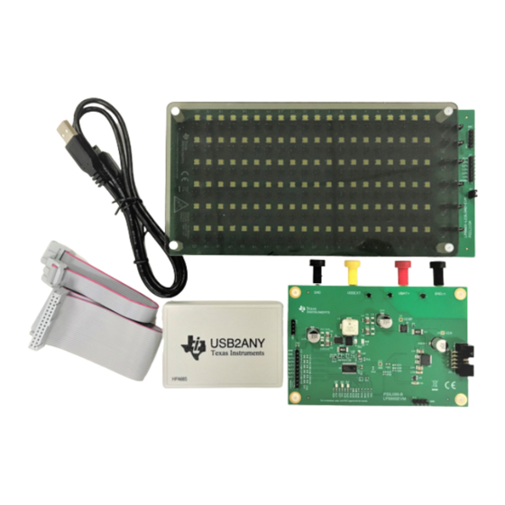
• Connect the USB2ANY module to the PC with the USB cable. • Connect the USB2ANY module to the LP8866EVM with the provided ribbon cable. • Connect the LP8866EVM to the LP886X-LEDLOAD-EVM with a 7-position ribbon cable. SNVU685A – December 2019 – Revised June 2020... -
Page 4: Lp8866Evm Hardware Setup
Test Setup www.ti.com Figure 2. LP8866EVM Hardware Setup Software Installation Download the GUI software from the LP8866EVM tools folder. Follow the instructions to finish the GUI installation. Once installed, a shortcut to the GUI is found on the desktop and also in the start-up menu under the Texas Instruments folder. -
Page 5: Lp8866/4 Family Gui Landing Page
If it shows "Hardware not Connected", click the button to connect to hardware manually. This button can be used to connect or disconnect the GUI to the hardware during the evaluation. 3. Click "EXPLORE LP8866" to go to the LP8866EVM GUI home page (see Figure Figure 4. -
Page 6: Lp8866Evm Led Control Page
Figure 5. LP8866EVM LED Control Page Additional GUI Functions In the selection tab on the left-hand side, the user can switch between LED Control, Monitor Faults, Diagnostics and Register Map tabs. -
Page 7: Lp8866Evm Monitor Faults Page
Test Setup www.ti.com Figure 6. LP8866EVM Monitor Faults Page 2.6.2 Diagnostics Page From the Diagnostics page (see Figure 7), the user can read back the following diagnostics register values and corresponding device status. • FSM_LIVE_STATUS: current status of the functional state machine •... -
Page 8: Lp8866Evm Diagnostics Page
Test Setup www.ti.com Figure 7. LP8866EVM Diagnostics Page 2.6.3 Register Map Page Figure 8 shows the registers map page. All the registers are available on this page. When "Auto Read" is set to other than "Off", all the registers will be read automatically and periodically according to the interval time the user selects. -
Page 9: Lp8866Evm Register Map Page
Figure 8. LP8866EVM Register Map Page Instructions for Standalone Evaluation The LP8866EVM can be used for standalone evaluation (without GUI software and PC connection). To support standalone mode, it must be modified from its default settings as described below: 1. Mount R20 to pull up EN input. -
Page 10: Lp8866Evm Board Layout
LP8866EVM Board Layout Figure 9 Figure 10 illustrate the EVM board layout. Figure 9. LP8866EVM Layout - Top Figure 10. LP8866EVM Layout - Bottom LP8866EVM User's Guide SNVU685A – December 2019 – Revised June 2020 Submit Documentation Feedback Copyright © 2019–2020, Texas Instruments Incorporated... -
Page 11: Lp8866Evm Schematic
LP8866EVM Schematic www.ti.com LP8866EVM Schematic Figure 11 shows the LP8866EVM schematic. Figure 11. LP8866EVM Schematic SNVU685A – December 2019 – Revised June 2020 LP8866EVM User's Guide Submit Documentation Feedback Copyright © 2019–2020, Texas Instruments Incorporated... -
Page 12: Lp8866Evm Bill Of Materials
LP8866EVM Bill of Materials www.ti.com LP8866EVM Bill of Materials Table 1 lists the bill of materials for the LP8866EVM. Table 1. LP8866EVM Bill of Materials Package Designator Value Part Number Manufacturer Description Reference !PCB1 PSIL099 Printed Circuit Board CAP, CERM, 10 µF, 75 V,+/-... - Page 13 LP8866EVM Bill of Materials www.ti.com Table 1. LP8866EVM Bill of Materials (continued) Package Designator Value Part Number Manufacturer Description Reference H5, H6, H7, 1902C Keystone Standoff PSIL110, LP886X-LEDLOAD- PSIL110 EVM, CDDS#: 6631820 USB2ANY USB2ANY, CDDS#: 6542513 J1, J6, J7 TSW-101-07-G-S...
- Page 14 LP8866EVM Bill of Materials www.ti.com Table 1. LP8866EVM Bill of Materials (continued) Package Designator Value Part Number Manufacturer Description Reference R24, R28, RES, 3.92 k, 1%, 0.1 W, AEC- 3.92k CRCW06033K92FKEA Vishay-Dale 0603 Q200 Grade 0, 0603 Stackpole RES, 11.0 k, 1%, 0.1 W, AEC- 11.0k...
-
Page 15: Led Load Board
J4, J5, J46, J47, J88, J90, J131, J132, J173, J174, J215 TSW-107-07-G-S Samtec Header, 100mil, 7x1, Gold, TH 7x1 Header SNVU685A – December 2019 – Revised June 2020 LP8866EVM User's Guide Submit Documentation Feedback Copyright © 2019–2020, Texas Instruments Incorporated... - Page 16 Changed resistors and connectors in Section 2.7..................• Changed LP8866EVM schematic in Figure .................. • Changed LP8866EVM bill of materials in Table Revision History SNVU685A – December 2019 – Revised June 2020 Submit Documentation Feedback Copyright © 2019–2020, Texas Instruments Incorporated...
- Page 17 STANDARD TERMS FOR EVALUATION MODULES Delivery: TI delivers TI evaluation boards, kits, or modules, including any accompanying demonstration software, components, and/or documentation which may be provided together or separately (collectively, an “EVM” or “EVMs”) to the User (“User”) in accordance with the terms set forth herein.
- Page 18 www.ti.com Regulatory Notices: 3.1 United States 3.1.1 Notice applicable to EVMs not FCC-Approved: FCC NOTICE: This kit is designed to allow product developers to evaluate electronic components, circuitry, or software associated with the kit to determine whether to incorporate such items in a finished product and software developers to write software applications for use with the end product.
- Page 19 www.ti.com Concernant les EVMs avec antennes détachables Conformément à la réglementation d'Industrie Canada, le présent émetteur radio peut fonctionner avec une antenne d'un type et d'un gain maximal (ou inférieur) approuvé pour l'émetteur par Industrie Canada. Dans le but de réduire les risques de brouillage radioélectrique à...
- Page 20 www.ti.com EVM Use Restrictions and Warnings: 4.1 EVMS ARE NOT FOR USE IN FUNCTIONAL SAFETY AND/OR SAFETY CRITICAL EVALUATIONS, INCLUDING BUT NOT LIMITED TO EVALUATIONS OF LIFE SUPPORT APPLICATIONS. 4.2 User must read and apply the user guide and other available documentation provided by TI regarding the EVM prior to handling or using the EVM, including without limitation any warning or restriction notices.
- Page 21 Notwithstanding the foregoing, any judgment may be enforced in any United States or foreign court, and TI may seek injunctive relief in any United States or foreign court. Mailing Address: Texas Instruments, Post Office Box 655303, Dallas, Texas 75265 Copyright © 2019, Texas Instruments Incorporated...
- Page 22 TI products. TI’s provision of these resources does not expand or otherwise alter TI’s applicable warranties or warranty disclaimers for TI products. Mailing Address: Texas Instruments, Post Office Box 655303, Dallas, Texas 75265 Copyright © 2020, Texas Instruments Incorporated...
Need help?
Do you have a question about the LP8866EVM and is the answer not in the manual?
Questions and answers