Table of Contents
Advertisement
Quick Links
Advertisement
Table of Contents

Related Manuals for Ruhrpumpen VCT


Summary of Contents for Ruhrpumpen VCT
- Page 1 Installation, Operation and Maintenance Manual...
-
Page 2: Table Of Contents
Vertical Circulating Turbine Pump CONTENTS 1. GENERAL ............................... 4 1.1 PUMP ELEMENT ..........................4 1.2 DISCHARGE COLUMN ........................4 1.3 NOZZLE HEAD ..........................5 1.4 DRIVER ............................. 5 2. SAFETY..............................6 2.1 IDENTIFICATION OF SAFETY INSTRUCTIONS IN THE OPERATING MANUAL ........6 2.2 QUALIFICATION AND TRAINING OF OPERATING PERSONNEL ............ - Page 3 Vertical Circulating Turbine Pump 5.1 OVERHAUL SCHEDULE ........................20 5.2 GASKETS ............................20 5.3 DISASSEMBLY AND REASSEMBLY ....................21 5.3.1 Disassembly of Coupling, Nozzle Head and Discharge Columns ..........21 5.3.2 Disassembly of Pump Bowl Assembly with Ring and Key Mounted Impellers ...... 22 5.3.3 Reassembly of Pump Bowl Assembly with Ring and Key Mounted Impellers .......
-
Page 4: General
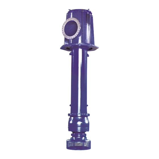
The VCT is a vertical diffuser pump defined by API 610 as a VS1. By multi-staging series stages, the VCT provides outstanding efficiencies and low cost operation in higher pressure applications. -
Page 5: Nozzle Head
Refer to sectional drawing or bill of materials. The VCT may be supplied with four types of discharge columns: i) self-lubricated, ii) self-lubricated with a pre-lubrication feature, iii) integral inner column, and iv) non-integral inner column. The inner column configuration may be supplied with oil lubrication, pressurized water lubrication or non- pressurized water lubrication. -
Page 6: Safety
The responsibilities and supervision of the personnel must be exactly defined by the plant operator. If the staff does not have the necessary knowledge, they must be trained and instructed. Training may be performed by a Ruhrpumpen representative on behalf of the plant operator. V3.061020... -
Page 7: Hazards In The Event Of Non-Compliance With The Safety Instructions
Vertical Circulating Turbine Pump Moreover, the plant operator is to make sure that the contents of the operating manual are fully understood by the personnel. 2.3 HAZARDS IN THE EVENT OF NON-COMPLIANCE WITH THE SAFETY INSTRUCTIONS Non-compliance with the safety instructions may produce a risk to the personnel as well as to the environment and the unit and results in loss of any right to claim damages. -
Page 8: Safety Instructions Relevant For Maintenance, Inspection And Assembly Work
Modifications may be made to the machine only after consultation with a Ruhrpumpen representative. Using spare parts and accessories authorized by Ruhrpumpen is in the interest of safety. The use of parts not authorized by the dealer exempt the manufacturer from any liability, voiding the warranty. -
Page 9: Installation Considerations
3.2 EFFECT OF ABRASIVES Ruhrpumpen makes no guarantee against the erosive action of sand or abrasive material suspended in pumped liquid. Abrasive passing through the pump will result in wear on internal parts, bearings, and wear rings. As the internal parts wear, pump performance and/or vibration levels will deteriorate. -
Page 10: Installation
Vertical Circulating Turbine Pump 3.5 INSTALLATION Lift the pump assembly off the skid with a sling around the nozzle head. On long units (in excess of 8 times the column diameter for smaller units to 4 times the column diameter for larger units) place a second sling half way down the bowl assembly to avoid undue strain on the pump when lifting. - Page 11 Vertical Circulating Turbine Pump Foot Pounds Torque x 1.3 = N-m. NOTE: Threaded surfaces to be lubricated to allow torque to achieve preload instead of friction. Stress is 17,000 psi for low strength bolting and 30,000 psi for high strength bolting. When compressing spiral wound gaskets, go over the bolting several times in a star pattern to full compression of this type of gasket.
-
Page 12: Mounting Driver
Vertical Circulating Turbine Pump 3.6 MOUNTING DRIVER Check the mounting flange dimensions and the shaft extension to make sure they will fit the nozzle head and drive half coupling that is being furnished. Support driver vertically. Thoroughly clean the driver shaft and both driver and nozzle head mounting flange faces. - Page 13 Vertical Circulating Turbine Pump Connect the electric wiring for the motor driven unit or steam inlet and exhaust piping for turbine driven units. Rotation of the motor shaft must be checked before continuing. Energize the power supply and jog the motor (the rotation must be counter-clockwise when viewed from the top of the motor).
-
Page 14: Rotating Assembly Adjustment (Impeller Lift)
Vertical Circulating Turbine Pump 3.7 ROTATING ASSEMBLY ADJUSTMENT (IMPELLER LIFT) Figure 3.2 Four piece, rigid coupling assembly drawing. V3.061020... - Page 15 Vertical Circulating Turbine Pump NOTE: Refer to the four piece coupling assembly drawing shown above. Prior to adjustment, ensure that the setting collar on the mechanical seal, if applicable, is loose and unattached to the pump shaft. The pump half coupling and the adjusting plate must be in place on the pump shaft (consult the sectional drawing).
- Page 16 Vertical Circulating Turbine Pump IMPORTANT: The impeller setting shown on the nameplate is for duty conditions. For any other condition, check the driver for signs of overload. This is done by checking the amperage drawn against the full load amperage stated on the motor nameplate. If the motor is being overloaded, the impeller might be rubbing against the case.
-
Page 17: Operation
Starting the driver with the wrong direction of rotation can cause damage to the pump and motor. 4.3 STARTING AND OPERATION The VCT pump was designed and built to operate at a specific design flow and duty point. For best results, the pump must be run at that flow. However, there are preferred and allowable operating regions as defined by API 610 and the Hydraulic Institute. - Page 18 Vertical Circulating Turbine Pump submergence requirements are met, Ruhrpumpen’s equipment should provide excellent long term service. Ruhrpumpen defines a pump’s preferred operating region in general (your pump may vary) as follows: • Minimum Flow is 80% of the Best Efficiency Point Flow or higher.
-
Page 19: Stopping
+/-5% of the values stamped on the pump’s nameplate. NOTE: Ruhrpumpen’s VCT pump is not designed to operate at flows less than 60% or with runout conditions greater than 120% than the pump’s best efficiency point flow. Operating the pump at these conditions may severely damage the pump and driver and affect the equipment’s warranty. -
Page 20: Maintenance
5.2 GASKETS Ruhrpumpen recommends that to avoid any possible chance of trouble which might develop with reused gaskets, that all new gaskets and O-rings be used during the maintenance of the pump. Thoroughly clean all the pump’s components and inspect them for wear. For best efficiency, all wear parts should be replaced. -
Page 21: Disassembly And Reassembly
Vertical Circulating Turbine Pump 5.3 DISASSEMBLY AND REASSEMBLY Refer to the pump’s sectional drawing. In order to check parts for wear and to replace those parts that are unserviceable, it is necessary to dismantle the entire unit. The pumped liquid and hazardous vapors must first be purged from the pump and adjacent piping. -
Page 22: Disassembly Of Pump Bowl Assembly With Ring And Key Mounted Impellers
Vertical Circulating Turbine Pump At this time and throughout the remainder of the dismantling procedure, exercise extreme care to avoid bending the shaft by always supporting the free end. Remove the nozzle head from the bolted column by removing the bolts (or nuts) and slide the head off the shaft. -
Page 23: Reassembly Of Pump Bowl Assembly With Ring And Key Mounted Impellers
Vertical Circulating Turbine Pump Remove the screws from the ring guard. Slide the ring guard off of the pump shaft. Remove the split ring from the shaft. Slide the impeller off of the shaft. Remove the impeller key from the shaft. Remove the next series case, if applicable. -
Page 24: Reassembly Of The Shaft Couplings
Vertical Circulating Turbine Pump Place the bottom end of each pump shaft into the bearing in the bottom case or suction case. Slide the shaft and impeller assembly into the case until the bottom of the impeller seals against the bottom case or impeller case. Bolt the suction case and the impeller case together before installation. -
Page 25: Press-In Bearing Installation
Vertical Circulating Turbine Pump Align the keyway on both the shaft and clamp the split ring around the knuckles on the shafts. The split rings should have a snug fit in holding the shafts together. Slide the coupling sleeve over the split ring. Insert the gib key(s) into the keyway(s) and slide the coupling over the gib key(s) until it contacts the shoulder on the gib key(s). -
Page 26: Bolt And Nut Bearing Installation
Vertical Circulating Turbine Pump Figure 5.1 Arbor press or hydraulic press bearing installation. 5.4.2 Bolt and Nut Bearing Installation The bolt and nut method of pressing bearing into the housing may be required when a press is not available. A plate is placed against the upper end of the bearing, as show in the figure below. The nut must be continuously drawn up. -
Page 27: Storage
Vertical Circulating Turbine Pump 6. STORAGE Storing any pump for any length of time presents a few challenges. Dirt, sand and moisture can play havoc on parts with close clearances, such as running clearances between impellers and cases and between bearings and shafting. Dirt and sand working their way through these areas can result in wear and the opening up of wear ring clearances to an extent that the efficiency of the pump may be affected shortly after startup. - Page 28 Vertical Circulating Turbine Pump Prevent foreign materials or dirt from entering the working parts of the pump or driver. Note that the driver’s lifting points are designed to lift only the driver. DO NOT USE these lifting points to lift the pump and driver assembly. Inspect the pump for shipping damage.
-
Page 29: Vertical Motor Storage
Vertical Circulating Turbine Pump The equipment, when opened for installation, may show evidence of loose, fluctuant rust. The presence of minor amounts of loose rust shall not be a cause for rejection and no re- cleaning is necessary. This films of rust are acceptable on non-critical, corrosion resistant material surfaces, provided there is no visible wall thickness deterioration, nor evidence of corrosion pitting. -
Page 30: Periodic Maintenance
Vertical Circulating Turbine Pump Bearings 1. Grease lubricated cavities must be completely filled with lubricant during the storage period. Remove the drain plug and fill the cavity with grease until grease begins to purge from the drain opening. Refer to the lubrication section of the driver manufacturer’s manual and/or check the motor’s lubrication nameplate for the correct lubricant. - Page 31 Vertical Circulating Turbine Pump All motors must have the shaft rotated once a month to ensure the maintenance of a coating lubricant film on the bearing races and journals. Insulation history: The only accurate way to evaluate the condition of the winding insulation is to maintain a history of the insulation readings.
- Page 32 Vertical Circulating Turbine Pump Figure 6.1 Insulation resistance temperature coefficient graph. Insulation resistance readings must not drop below the value indicated by the following formula: Rm = Kv + 1 Where: Rm: Minimum insulation (in megohms) at 40°C. Kv: Rated motor voltage in kilovolts. Dielectric absoption ratio: In addition to the individual test reading, a dielectric absorption ratio may be required.
-
Page 33: Start-Up Preparations After Storage
Vertical Circulating Turbine Pump The ratio is obtained by dividing the second reading by the first reading and is based on a good insulation system increasing its resistance when subjected to a test voltage for a period of time. The ratios are as follows: 10 Minute : 1 Minute 60 Second : 30 Second Dangerous = Less the 1.0... -
Page 34: Protective Materials
Vertical Circulating Turbine Pump 6.3.5 Protective Materials WRAPPING VPI paper that meets federal specifications MIL-P-3420, Type 1, Class I and II, Style A, with polyethylene coating applied to one side, or polyethylene sheets, with a minimum of 3 mil. thickness. RUST PREVENTATIVE CRC "Store and Lube"... -
Page 35: Parts Information
Vertical Circulating Turbine Pump 7. PARTS INFORMATION DETAIL A DETAIL B DETAIL C V3.061020... - Page 36 Vertical Circulating Turbine Pump DETAIL D DETAIL E Figure 7.1 VCT Pump Single Stage Open Shaft Packing Strips Seal Option Sectional Drawing. V3.061020...
- Page 37 Vertical Circulating Turbine Pump Parts List VCT Pump Single Stage Open Shaft Packing Strips Seal Option. ITEM DESCRIPTION ITEM DESCRIPTION CASE 720-2 INLINE TEE DISCHARGE CASE 720-3 PIPE NIPPLE CASE LINER 720-4 NPT CONNECTOR SUCTION BELL 720-5 STRAIGHT TUBE ADAPTER...
- Page 38 Vertical Circulating Turbine Pump DETAIL A DETAIL B DETAIL C Figure 7.2 VCT Pump Single Stage Open Shaft Mechanical Seal Option Sectional Drawing. V3.061020...
- Page 39 Vertical Circulating Turbine Pump Parts List VCT Pump Single Stage Open Shaft Mechanical Seal Option. ITEM DESCRIPTION ITEM DESCRIPTION 112.1 IMPELLER BOWL 501.2 DRIVER COUPLING SPLIT RING 112.2 DISCHARGE BOWL BOWL WEAR RING SUCTION BELL IMPELLER WEAR RING BASKET STRAINER 545.1...
- Page 40 Vertical Circulating Turbine Pump DETAIL A Figure 7.3 VCT Pump Single Stage Closed Shaft Packing Strips Seal Option Sectional Drawing. V3.061020...
- Page 41 Vertical Circulating Turbine Pump Parts List VCT Pump Single Stage Closed Shaft Packing Strips Seal Option. ITEM DESCRIPTION ITEM DESCRIPTION UPPER BOWL LOWER COLUMN TUBE 418-1 IMPELLER ALIGNER INTERMEDIATE COLUMN TUBE DISCHARGE HEAD MOTOR SUPPORT SUCTION BELL MOTOR COUPLE STUFFING BOX COVER...
- Page 42 Vertical Circulating Turbine Pump DETAIL A DETAIL B DETAIL C DESIGN CLEARANCE ACCORDING TO API 610 LATEST EDITION WEAR RING CLEARANCE Figure 7.4 VCT Pump Multi-Stage Open Shaft Packing Strips Seal Option Sectional Drawing. V3.061020...
- Page 43 Vertical Circulating Turbine Pump Parts List VCT Pump Multi-Stage Open Shaft Packing Strips Seal Option. ITEM DESCRIPTION ITEM DESCRIPTION INTERMEDIATE BOWL DEVIATOR 501.1 DISCHARGE BOWL FIRST STAGE SPLIT KEY 501.2 ALIGNER SECOND STAGE SPLIT KEY SUCTION BELL BOWL WEAR RING...
- Page 44 Vertical Circulating Turbine Pump Figure 7.5 VCT Pump Multi-Stage Open Shaft Mechanical Seal Option Sectional Drawing. V3.061020...
- Page 45 Vertical Circulating Turbine Pump Parts List VCT Pump Multi-Stage Open Shaft Mechanical Seal Option. ITEM DESCRIPTION ITEM DESCRIPTION INTERMEDIATE BOWL 501.01 IMPELLER FIRST STAGE SPLIT RING DISCHARGE BOWL 501.02 IMPELLER SECOND STAGE SPLIT RING IMPELLER ALIGNER 501.03 MOTOR COUPLING SPLIT RING SUCTION BELL 545.1...
- Page 46 Vertical Circulating Turbine Pump Figure 7.6 VCT Pump Multi-Stage Closed Shaft Mechanical Seal Option Sectional Drawing. V3.061020...
- Page 47 Vertical Circulating Turbine Pump Parts List VCT Pump Muti-Stage Closed Shaft Mechanical Seal Option. ITEM DESCRIPTION ITEM DESCRIPTION DISCHARGE BOWL 501.1 SPLIT RING INTERMEDIATE BOWL 501.2 SPLIT RING IMPELLER ALIGNER 501.3 SPLIT RING SUCTION BELL BOWL WEAR RING DISCHARGE NOZZLE...
- Page 48 +65 years creating the pumping technology that moves our world Ruhrpumpen is an innovative and efficient pump technology company that offers highly-engineered and standard pumping solutions for the oil & gas, power generation, industrial, water and chemical markets. We offer a broad range of centrifugal and reciprocating pumps that meet and exceed the requirements of the most demanding quality specifications and industry standards such as API, ANSI, UL, FM, ISO and Hydraulic Institute.
Need help?
Do you have a question about the VCT and is the answer not in the manual?
Questions and answers