Table of Contents
Advertisement
Quick Links
Advertisement
Table of Contents

Subscribe to Our Youtube Channel
Related Manuals for Ruhrpumpen VLT


Summary of Contents for Ruhrpumpen VLT
- Page 1 Installation, Operation and Maintenance Manual...
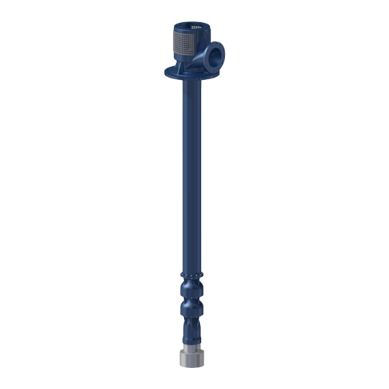
- Page 2 Vertical Process Pump FOREWORD The VLT pump is a vertical process pump with one or more stages that are connected to a fabricated nozzle head by one or more columns pipes. The entire pump and column assembly are suspended in a suction receiving can.
- Page 3 Care must also be taken to prevent ignition of flammable fluids or other material. Information in this manual is believed to be reliable, but it is not guaranteed by Ruhrpumpen as to its completeness or accuracy. © 2018 Ruhrpumpen All Rights Reserved.
-
Page 4: Table Of Contents
Vertical Process Pump CONTENTS 1. PRODUCT DESCRIPTION ........................7 1.1 INTRODUCTION ..........................7 1.2 PUMP BOWLS, IMPELLER, AND WEAR RINGS ................. 8 1.2.1 Pump Bowls ..........................8 1.2.2 Impeller and Wear Rings ......................8 1.3 NOZZLE HEAD ..........................8 1.4 SUCTION CAN ..........................9 1.5 COLUMN TUBE .......................... - Page 5 Vertical Process Pump 4. INSTALLATION ............................. 19 4.1 FOUNDATION ..........................19 4.2 EQUIPMENT NECESSARY FOR INSTALLATION ................19 4.3. LIFTING PUMP TO A VERTICAL STANCE ..................20 4.3.1 Two Crane Method ......................... 20 4.3.2 One Crane Method ......................... 21 4.4 INSTALLATION ..........................23 4.4.1 Pump Installation Procedure ....................
- Page 6 Vertical Process Pump 8.2 INSPECTION AND CLEANING ......................54 8.3 REASSEMBLY ..........................55 8.3.1 VLT Pump Reassembly ......................55 9. SPARE PARTS ............................73 10. PARTS INFORMATION ........................75 11. TROUBLESHOOTING CHART......................79 V1.090418...
-
Page 7: Product Description
1.1 INTRODUCTION The VLT pump is a vertical process pump with one or more stages that are connected to a fabricated nozzle head by one or more discharge columns. The entire pump and column assembly are suspended in a suction receiving can. -
Page 8: Pump Bowls, Impeller, And Wear Rings
O-ring gaskets. Each bowl is furnished with renewable wear rings. 1.2.2 Impeller and Wear Rings Impellers used in Ruhrpumpen VLT process pumps are supported between bearings. Each impeller is dynamically balanced and secured to the pump shaft by a split retaining ring and a retaining ring guard with the impeller being locked to the shaft by a key or by an impeller collet. -
Page 9: Suction Can
The pump shaft is constructed using stainless steel and in one piece whenever possible. 1.7 SHAFT SEALING VLT pumps are supplied with a single cartridge mechanical seal as standard. Single and double (back- to-back or tandem) mechanical seals can be used. The stuffing box is designed to accommodate all state-of-the-art mechanical seals according to API 610 and API 682. -
Page 10: Safety
The responsibilities and supervision of the personnel must be exactly defined by the plant operator. If the staff does not have the necessary knowledge, they must be trained and instructed. Training may be performed by a Ruhrpumpen representative on behalf of the plant operator. V1.090418... -
Page 11: Hazards In The Event Of Non-Compliance With The Safety Instructions
Vertical Process Pump Moreover, the plant operator is to make sure that the contents of the operating manual are fully understood by the personnel. 2.3 HAZARDS IN THE EVENT OF NON-COMPLIANCE WITH THE SAFETY INSTRUCTIONS Non-compliance with the safety instructions may produce a risk to the personnel as well as to the environment and the unit and results in loss of any right to claim damages. -
Page 12: Safety Instructions Relevant For Maintenance, Inspection And Assembly Work
Modifications may be made to the machine only after consultation with a Ruhrpumpen representative. Using spare parts and accessories authorized by Ruhrpumpen is in the interest of safety. The use of parts not authorized by the dealer exempt the manufacturer from any liability, voiding the warranty. -
Page 13: Transport & Storage
Handle all equipment carefully. Remove unit only by properly supporting the wooden shipping skid. After unloading, inspect the pump, check the shipment against the packing list, and report damages or shortages immediately to freight carrier and to the designated Ruhrpumpen representative. 3.3 TRANSPORT ... -
Page 14: Storing
Vertical Process Pump Figure 3.1. Correct position of the lifting ropes or chains, side view. 3.4 STORING Storing any pump for any length of time presents a few challenges. Dirt, sand and moisture can cause serious damage on parts with close clearances, such as running clearances between impellers and cases and between bearings and shafting. -
Page 15: Long Term Storage (Longer Than Six Months)
Vertical Process Pump should remain inside its shipping container. Furthermore, the pump unit (pump, driver, etc.) should not be subject to sudden temperature changes or vibrations. 3.4.2 Long Term Storage (Longer than Six Months) For long term storage each part of the pump should be individually prepared. Comply with the following steps: Remove pump from shipping skids and supports, but do not damage them because the unit is to be placed in them again. -
Page 16: Motor (Driver) Storage
Return the unit to the shipping crate. When the pump is to be installed, remove all the protective coatings and desiccant or drain all oils. One month before installation, a Ruhrpumpen representative should be employed to conduct a final inspection. 3.4.3 Motor (Driver) Storage To properly store the motor (driver) for periods longer than one month, follow the manufacturer’s... -
Page 17: Conservation
Vertical Process Pump o If none are available, single phase or “trickle” heating may be utilized by energizing one phase of the motor’s windings with a low voltage, producing heat in the winding conductor. Request the required voltage and transformer capacity from the driver manufacturer. - Page 18 Vertical Process Pump Anticorrosive layers inside the pump housing must be removed with process neutral solvents before commencing pump operation. When removing the protective coating with a neutral solvent, follow the safety instructions of the solvent manufacturer carefully. ...
-
Page 19: Installation
NOTE: The information in this section is intended as a general guideline. For further information refer to the corresponding section in API Recommended Practices 686. IMPORTANT: The design of foundations is not the responsibility of Ruhrpumpen. It is therefore recommended that the customer consult a competent specialist skilled in the field of foundations, to insure proper design/installation of the foundation. -
Page 20: Lifting Pump To A Vertical Stance
Vertical Process Pump Column pipe clamps. Chain tongs (for threaded bowl assemblies). Hook chain or cable sling. A set of Millwright’s Tools Collet driver and shaft locating plug (special tools for bowl assembly). Protective compound for all threaded connections. 4.3. -
Page 21: One Crane Method
Vertical Process Pump on the discharge nozzle is slowly raised in order to tilt the pump towards a vertical stance like the figure shown below: Figure 4.2 Tilting the pump towards a vertical stance using the two crane method. Once the pump is in a vertical stance, the rope or sling attached around the middle of the bowl assembly may be released and the rest of the transportation can be carried out using only the crane whose ropes or slings are attached to the lifting lugs on the discharge nozzle. - Page 22 Vertical Process Pump Figure 4.3 Attaching ropes or slings to the pump to lift it using the one crane method. With the pump still in the wooden support skid, begin raising the top end of the pump with the crane, using the wooden support skid as a pivot, to tilt the pump into a vertical stance, as shown below: Figure 4.4 Tilting the pump into a vertical stance using the one crane method.
-
Page 23: Installation
Vertical Process Pump 4.4 INSTALLATION Before starting the installation it is recommended to hire an electrician to connect the motor after the installation. WARNING: Residues and loose materials must be taken out of the well before installing the pump. If a strainer is installed on the suction bowl, care must be taken to avoid damaging it during transportation. - Page 24 Vertical Process Pump Figure 4.5 Above ground suction nozzle (style “SH”) and below ground suction nozzle (style “SB”). Check that the suction can is free from any foreign material. Place the suction can in its place on the drilled hole. Tie a rope or chain around the nozzle head to lift the pump of its wooden shipping skid.
- Page 25 Vertical Process Pump Adjust the rotating assembly as described in Section 4.3.3 Rotating Assembly Adjustment. Adjust the mechanical seal. Refer to the seal manufacturer’s manual for further reference. Tighten all the fasteners according to the values given in the Torque Value for Fasteners Table.
-
Page 26: Driver Mounting
Vertical Process Pump 4.4.2 Driver Mounting NOTE: Pumps supplied with a thrust pot have specific instructions that detail how to mount the driver. For external thrust pots, follow specific instructions supplied separately to mount the driver and continue with step 3 and onwards from the instructions below to connect the thrust pot shaft (as driver shaft) to the pump shaft. -
Page 27: Rotating Assembly Adjustment (Impeller Lift)
Vertical Process Pump d. Use the driver alignment jack screws to reduce the total indicated run-out to or below the following limits, according to the pump’s specific RPM: 0.002 inch (0.05 mm) for pumps running at 3000/3600 RPM. 0.004 inch (0.10 mm) for pumps running at 1500/1800 RPM or lower. ... - Page 28 Vertical Process Pump Place two of the coupling bolts 180 degrees apart and tighten them progressively, closing the gap between the spacer and the adjusting plate. Insert the other two coupling bolts and tighten them. Attach the Total Indicator Readout (TIR) tool 1 inch above the mechanical seal, being careful not to force the shaft radially, and turn the shaft.
-
Page 29: Grout
Vertical Process Pump The impeller setting shown on the pump’s nameplate is for duty conditions. For any other working conditions, check the driver for signs of overload. This is performed by comparing the amperage drawn against a full load amperage as stated in the nameplate. - Page 30 Vertical Process Pump Cover the surface of the grout with a wet sackcloth to allow it to slowly dry. After the grout has forged for 48 hours, remove the wooden form and smooth the surface. Let the grout forge for an additional 72 hours before operating the pump. V1.090418...
-
Page 31: Piping And Alignment
Vertical Process Pump 5. PIPING AND ALIGNMENT These units are furnished for a specific service condition. Any change in the hydraulic system may affect the pump performance adversely. The connection of the piping must be carried out with utmost care; otherwise, the pumping medium can escape during operation, which can seriously endanger the operating personnel. -
Page 32: Piping The System
API Recommended Practices 686. IMPORTANT: The design of piping and related systems is not the responsibility of Ruhrpumpen. It is, therefore recommended that the customer consult a competent specialist skilled in the field of piping to insure proper design/installation of all the piping. - Page 33 Vertical Process Pump Disconnect the piping from the pump if you heat one side of the pipe to align the pipe to the pump. Pump and pipe flanges must be parallel; they should mate together without effort, and with the bolt holes properly in line. Check the fine alignment by clocking or using a Dial Type Indicator (DTI) on the coupling.
-
Page 34: Alignment
Vertical Process Pump 5.2 ALIGNMENT* In the following pages, alignment procedures are explained with dial indicators. Laser alignment is also possible. The specific method in laser alignment will depend on the manufacturer’s instructions; however, the basic principles and rotation of the shafts apply, as in the Reverse Indicator Alignment Method. - Page 35 Vertical Process Pump 3. Thermal Growth If there are thermal growth considerations on the piece of equipment, it is a good idea to get these numbers so that they can be added to or subtracted from the graphical solution before the equipment move is made, this is known as “Hot alignment”.
- Page 36 Vertical Process Pump Figure 5.1. Example for reverse indicator graphical analysis. The next step is to determine indicator sag. Set up your bracket arrangement on a pipe. Set the indicator at '0' on top. Roll set up until indicator is at the bottom of pipe. It will read negative. In this example, it is found to be -0.005 inch (-0.127 mm).
- Page 37 Vertical Process Pump Figure 5.2. Indicator sag. With the indicator bracket attached to the motor hub reading off the pump hub, rotate unit in 90° increments and take readings. Bottom reading is then corrected for indicator sag. Indicator sag in the example was determined to be -0.005 inch (-0.127 mm).
- Page 38 Vertical Process Pump Figure 5.3. Motor shaft extension relative to the pump shaft center line. Now with the indicator bracket attached to the pump hub reading off the motor hub, rotate unit again in 90° increments. NOTE: If you can set up both indicators at once, both sets of readings can be taken at one time.
- Page 39 Vertical Process Pump We have now located the motor shaft theoretical extension in two places: A. In the plane of the pump hub. B. In the plane of the motor hub. Drawing a straight line through these two points crossing the plane of the two motor feet. The shim adjustment can now be read directly off the graph.
- Page 40 Vertical Process Pump Figure 5.6. Reverse indicator alignment of more than two units. D. ACROSS THE DISC PACK ALIGNMENT GRAPHICAL ANALYSIS When the distance between disc packs is long where it is not practical to try to span the distance with indicator bracketry, the 'across the disc pack method' can be used.
- Page 41 Vertical Process Pump The next step is to determine indicator sag. Set up your bracket arrangement on a pipe. Set the indicator at '0' on top. Roll set up until indicator is at the bottom of pipe. It will read negative. In this example, it was found to be -0.004 inch (-0.102 mm).
- Page 42 Vertical Process Pump Figure 5.9. Plot of the plus reading in the across the disc pack alignment analysis example. Now with the indicator bracket attached to the motor hub reading out on the center member, rotate the unit in 90° increments and take readings. Bottom reading is corrected for indicator sag: ±0.008 inch (±0.203 mm) -0.004 inch (0.102 mm) = +0.012 inch (+0.309 mm).
- Page 43 Vertical Process Pump Figure 5.10. Plotting the motor in the across the disc pack alignment analysis example. In this example, the motor should be shimmed up 0.013 inch (0.330 mm) under front feet and shimmed up 0.016 inch (0.406 mm) under back feet. This solution can also be done by use of a pre-programmed, calculator for faster results.
-
Page 44: Lubrication
Vertical Process Pump 6. LUBRICATION 6.1 BUSHING LUBRICATION 6.1.1Self-Lubricating Bushings Self-lubricating bushings are lubricated using the same fluid that is being pumped. As the fluid rises thru the column tube, the fluid bleeds thru the bushings, keeping them lubricated 6.1.2 Oil Lubricated Bushings Oil lubricated bushings depend on an oil tank and a dripper to remain lubricated. - Page 45 Fill the oil tank with suitable oil. 6.1.3 Grease Lubricated Bushings When the fluid being pumped is not deemed sufficient to correctly lubricate a VLT pump, the bushings can be lubricated using grease. Grease lubricated bushings require grease to be directly injected to them for proper lubrication.
-
Page 46: Operation
Vertical Process Pump 7. OPERATION 7.1 PRIMING • A centrifugal pump must always be completely filled with the liquid to be pumped each time before starting. • Do not attempt to run the pump dry or serious and costly damage may result, as wear parts within the pump depend on the pumped fluid for lubrication. - Page 47 Vertical Process Pump Figure 7.1. Seal setting devices. Position of discharge valve on starting A high or medium head centrifugal pump operated at full speed with the discharge gate valve closed will require much less energy than when it is operated at its rated head and flow with the gate valve open.
- Page 48 Vertical Process Pump • Discharge valve closed. • Suction valve (if used) open. • Seal water valve (if used) open. • Motor and pump properly lubricated. Only after these items have been checked should the pump be started. WARNING: Exposed coupling and shafting between pump and driver must be protected with coupling guard and/or shaft guard prior to pump start-up and operation.
-
Page 49: Operating Check
To monitor flow, pressure, temperature, and lubrication, regular visual inspection and monitoring is advisable and/or necessary during operation. Ruhrpumpen recommends checking the pump constantly at regular intervals in order to detect problems early, in case they arise. The operational check routine must include at least the following points: ... -
Page 50: Doweling (Optional)
Vertical Process Pump • Monitor the power consumption of the drive motor. Low or excessive power consumption may indicate a possible fault. • Check the sealing system: a. Refer to the seal manufacturer for his estimate of maximum acceptable leakage rate, as this will depend on application, design, location, and the sealed liquid characteristics. -
Page 51: Short-Term Shutdown
Vertical Process Pump If the rotor is jerky or suddenly stops, there is danger that the rotor has become blocked. The pump must be opened and all running clearances checked. Ensure the drive motor cannot be unintentionally turned on. Ensure the shut-off devices in the suction and pressure pipes cannot be unintentionally opened. -
Page 52: Maintenance
IMPORTANT: For any component/accessory that has not been manufactured by Ruhrpumpen and is part of the pump’s equipment, a complete reading of said component/accessory manufacturer’s manual must be carried out for further information on proper maintenance procedures and relevant safety warnings. - Page 53 Vertical Process Pump When disassembling the pump, match mark, tag or otherwise identify all parts, and provide separate containers for small parts. Refer to the sectional drawing of the pump included in SECTION TEN - PARTS INFORMATION for the correct identification of the parts. Disconnect seal water lines (if used).
-
Page 54: Inspection And Cleaning
Thoroughly clean all parts and dry with compressed air or a clean, lint free cloth. Inspect all components for corrosion, erosion, pitting, and scoring. If required, replace with Ruhrpumpen O.E.M. genuine replacement parts. Visual check all individual parts for any damage. -
Page 55: Reassembly
Observe the plant's safety precautions when lifting heavy components. Request help when moving or positioning them. 8.3.1 VLT Pump Reassembly Insert the impeller wear ring on the impeller from the hub side. If you pump’s size is 100, 200, 600, 650, 850 or 950, skip this step and begin with step 2. - Page 56 Vertical Process Pump Insert the impeller inside the intermediate bowl. Figure 8.3 Inserting the impeller inside the intermediate bowl. Insert the impeller bushing inside the impeller. Figure 8.4 Inserting the impeller bushing inside the impeller. If your pump is furnished with more than one intermediate bowl, repeat steps 1 thru 4 to assemble each one.
- Page 57 Vertical Process Pump Place and tighten the hex bolts to secure the second intermediate bowl to the first intermediate bowl. Figure 8.6 Placing and tightening the hex bolts to secure the second intermediate bowl to the first intermediate bowl. Repeat steps 6 and 7 to assemble all the intermediate bowls your pump is equipped with.
- Page 58 Vertical Process Pump Insert the suction bowl sand collar inside the suction bowl. Figure 8.8 Inserting the suction bowl sand collar inside the suction bowl. Place the suction bowl assembly on the intermediate bowl assembly. Figure 8.9 Placing the suction bowl assembly on the intermediate bowl assembly. V1.090418...
- Page 59 Vertical Process Pump Place and tighten the hex bolts to secure the suction bowl assembly to the intermediate bowl assembly. Figure 8.10 Placing and tightening the hex bolts to secure the suction bowl assembly to the intermediate bowl assembly. Insert the impeller shaft inside the intermediate bowl assembly and the suction bowl assembly.
- Page 60 Vertical Process Pump Place and tighten the suction bowl plug on the suction bowl. Figure 8.12 Placing and tightening the suction bowl plug. Insert the shaft bushing over the impeller shaft. Figure 8.13 Inserting the shaft bushing over the impeller shaft. V1.090418...
- Page 61 Vertical Process Pump Place the column pipe on the last intermediate bowl (or the previous column pipe in case your pump is equipped with more than one column pipe). Figure 8.14 Placing the column pipe on the last intermediate bowl (or the previous column pipe). Place the hex bolts that fix the column pipe to the intermediate bowl assembly (or to the column pipe in case your pump is equipped with more than one column pipe).
- Page 62 Vertical Process Pump Place and tighten the hex nuts to secure the column pipe to the intermediate bowl assembly (or column pipe in case your pump is equipped with more than one column pipe). Figure 8.16 Placing and tightening the hex nuts to secure the column pipe to the intermediate bowl assembly (or column pipe in case your pump is equipped with more than one column pipe).
- Page 63 Vertical Process Pump Insert the shaft sleeve inside the column bushing. Figure 8.18 Inserting the shaft sleeve inside the column bushing. Place the bushing carrier assembly on top of the column pipe. Figure 8.19 Placing the bushing carrier assembly on the top of the column pipe. V1.090418...
- Page 64 Vertical Process Pump Insert the shaft inside the bushing carrier assembly and column pipe. Figure 8.21 Inserting the shaft inside the bushing carrier assembly and column pipe. If your pump is equipped with more than one column pipe, repeat steps 15 thru 22 to install all additional column pipes on top of the last column pipe installed.
- Page 65 Vertical Process Pump Place and tighten the hex bolts to secure the nozzle head to the last column pipe. Figure 8.23 Placing and tightening the hex bolts to secure the nozzle head to the last column pipe. Place a gasket on the shaft hole of the nozzle head. Figure 8.24 Placing a gasket in the shaft hole of the nozzle head.
- Page 66 Vertical Process Pump Insert the stuffing box bushing inside the stuffing box until it reaches the inner shoulder. Figure 8.25 Inserting the stuffing box bushing inside the stuffing box. Insert the stuffing box over the last intermediate shaft inside the nozzle head. Figure 8.26 Inserting the stuffing box inside the nozzle head.
- Page 67 Vertical Process Pump Place and tighten the hex bolts that secure the stuffing box to the nozzle head. Figure 8.27 Placing and tightening the hex bolts to secure the stuffing box to the nozzle head. To assemble the mechanical seal please follow the next steps: a.
- Page 68 Vertical Process Pump b. Insert the mechanical seal gland over the shaft inside the stuffing box until it reaches the mechanical seal. Figure 8.29 Inserting the mechanical seal gland inside the stuffing box. c. Place the studs to hold the mechanical seal gland in its place in the nozzle head. Figure 8.30 Placing the studs to hold the mechanical seal gland in its place in the nozzle head.
- Page 69 Vertical Process Pump d. Place and tighten the hex nuts on the studs to secure the mechanical seal gland to the nozzle head. Figure 8.31 Placing and tightening the hex nuts to secure the mechanical seal gland to the nozzle head. Place the grease fitting in its corresponding hole in the nozzle head.
- Page 70 Vertical Process Pump Install the coupling guard on the nozzle head. Figure 8.33 Installing the coupling guard on the nozzle head. Install the strainer in the bottom of the suction bowl. Figure 8.34 Installing the strainer in the bottom of the suction bowl. V1.090418...
- Page 71 Vertical Process Pump Place all the plugs on the nozzle head. Figure 8.35 Placing all the plugs on the nozzle head. V1.090418...
- Page 72 Vertical Process Pump VLT pump assembly is complete. Figure 8.36 Complete VLT pump assembly. V1.090418...
-
Page 73: Spare Parts
The quantities of spare parts given on the list below are the minimum standard quantities to be had. However, these quantities may vary depending on individual working conditions. For more information, please contact a Ruhrpumpen representative. DESCRIPTION STARTUP 1 - 3 YEARS... - Page 74 Vertical Process Pump Material Storage of Spare Parts • Store the spare parts in their original packaging. • Store in a dry place, preferably at a constant temperature. • Check the spare parts and the state of the packaging every 6 months for signs of corrosion. •...
-
Page 75: Parts Information
Vertical Process Pump 10. PARTS INFORMATION DETAIL A DETAIL B DETAIL C Figure 10.1 VLT Pump Self-Lubricating Option Sectional Drawing. V1.090418... - Page 76 PUMP HALF COUPLING KEY Multiple combinations of the X, L, H, and M impellers can be used to suit each individual pump according the required operating factors for each individual project. Contact your Ruhrpumpen representative for more information. V1.090418...
- Page 77 Vertical Process Pump Figure 10.2 VLT Pump Oil Lubrication Option Sectional Drawing. V1.090418...
- Page 78 Vertical Process Pump Parts List VLT Pump Oil Lubrication Option. ITEM DESCRIPTION ITEM DESCRIPTION TOP CASE BOTTOM FLANGED COLUMN TUBE INTERMEDIATE BOWL 418-1 FLANGED COLUMN TUBE SUCTION BELL FOUNDATION PLATE DISCHARGE NOZZLE PACKED TENSION RING SUCTION BELL BUSHING PACKING RING PUMP SHAFT "V"...
-
Page 79: Troubleshooting Chart
SUGGESTED SOLUTION a. Inner pump parts are a. Change worn parts. worn. b. Consult a Ruhrpumpen dealer. b. Density or viscosity of c. Apply correct voltage to the motor. pumped fluid is not same d. Check the cables, connections and fuses. - Page 80 Install vent valve or lay piping elsewhere. plugged. j. Change worn parts. CAPACITY OR Formation k. Consult a Ruhrpumpen dealer. DISCHARGE pockets in the piping. l. Apply correct voltage to the motor. PRESSURE LOW j. Inner pump parts are m.
- Page 81 Vertical Process Pump RUHRPUMPEN PLANTS USA, Tulsa & Orland MEXICO, Monterrey BRAZIL, Río De Janeiro ARGENTINA, Buenos Aires GERMANY, Witten EGYPT, Suez INDIA, Chennai CHINA, Changzhou UK, Lancing V1.090418 V1.090418...
Need help?
Do you have a question about the VLT and is the answer not in the manual?
Questions and answers