Table of Contents
Advertisement
Quick Links
Advertisement
Table of Contents

Subscribe to Our Youtube Channel
Related Manuals for Ruhrpumpen API 610


Summary of Contents for Ruhrpumpen API 610
- Page 2 Contact with hot surfaces of the pump can cause severe burns. Care must be taken where such surfaces are exposed. Care must also be taken to prevent ignition of flammable fluids or other material. Information in this manual is believed to be reliable, but it is not guaranteed by Ruhrpumpen as to its completeness or accuracy.
-
Page 3: Table Of Contents
J Line Pump Horizontal Double Suction Centrifugal Pump – API 610 Process Pump INDEX 1. PRODUCT DESCRIPTION ..........................6 1.1 INTRODUCTION ............................6 1.2 PUMP CASE, IMPELLER, AND WEAR RINGS ..................7 1.2.1 Pump Case .............................7 1.2.2 Impeller and Wear Rings ........................7 1.3 BEARING HOUSING ..........................7 1.4 LUBRICATION ............................8... - Page 4 J Line Pump Horizontal Double Suction Centrifugal Pump – API 610 Process Pump 4.3.3 Grouting Procedure ........................22 5. PIPING AND ALIGNMENT .........................25 5.1 PIPING THE SYSTEM ..........................26 5.2 ALIGNMENT* ............................28 LUBRICATION............................39 6.1 OIL LUBRICATED BEARINGS ........................39 6.1.1 Recommended Lubricant ......................39 6.1.2 Method of Application .........................39...
- Page 5 J Line Pump Horizontal Double Suction Centrifugal Pump – API 610 Process Pump 8.1.2 JD Line Pump Disassembly ......................55 8.2 INSPECTION AND CLEANING ......................58 8.2.1 Casing wear ring and impeller wear ring inspection and replacement ........59 8.3 REASSEMBLY ............................59 8.3.1 J Line Pump ..........................59 8.3.2 JD-Line Pump ..........................92...
-
Page 6: Product Description
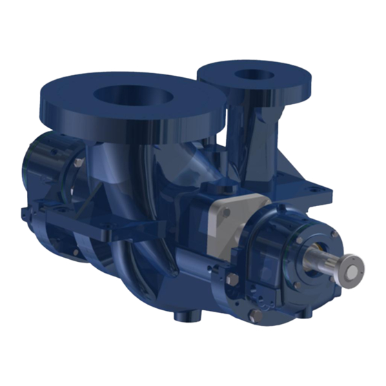
JD configuration offers both axial and radial casing covers. All J line pumps are designed to comply with the latest edition of API 610. These pumps are designed for continuous duty pumping of various fluids with combinations of metallurgical, mechanical, and installation features for application in petroleum, petrochemical, water and industrial products V1.032818... -
Page 7: Pump Case, Impeller, And Wear Rings
J Line Pump Horizontal Double Suction Centrifugal Pump – API 610 Process Pump industries. These pumps’ rotation can be either clockwise or counterclockwise as viewed from the driver (coupling) end. The following information is included in the nameplate of your pump unit: ... -
Page 8: Lubrication
J Line Pump Horizontal Double Suction Centrifugal Pump – API 610 Process Pump 1.4 LUBRICATION Bearings in this pump are lubricated by oil as a standard. Periodic inspection of bearing lubrication should be made and additional oil must be added as needed. -
Page 9: Safety
The responsibilities and supervision of the personnel must be exactly defined by the plant operator. If the staff does not have the necessary knowledge, they must be trained and instructed. Training may be performed by a Ruhrpumpen representative on behalf of the plant operator. Moreover, V1.032818... -
Page 10: Hazards In The Event Of Non-Compliance With The Safety Instructions
J Line Pump Horizontal Double Suction Centrifugal Pump – API 610 Process Pump the plant operator is to make sure that the contents of the operating manual are fully understood by the personnel. 2.3 HAZARDS IN THE EVENT OF NON-COMPLIANCE WITH THE SAFETY INSTRUCTIONS Non-compliance with the safety instructions may produce a risk to the personnel as well as to the environment and the unit and results in loss of any right to claim damages. -
Page 11: Safety Instructions Relevant For Maintenance, Inspection And Assembly Work
Modifications may be made to the machine only after consultation with a Ruhrpumpen representative. Using spare parts and accessories authorized by Ruhrpumpen is in the interest of safety. The use of parts not authorized by the dealer exempt the manufacturer from any liability, voiding the warranty. -
Page 12: Transport & Storage
Ruhrpumpen during the quoting process, as this requires an analysis and design of a special, customized baseplate. If during the quoting process the customer fails to notify Ruhrpumpen the request that all the components be forcibly mounted on the baseplate during shipment, Ruhrpumpen may ship all components mounted on the baseplate, prior written request from the customer, under the customer’s responsibility of the risks of deformation during transport. -
Page 13: Transport
J Line Pump Horizontal Double Suction Centrifugal Pump – API 610 Process Pump 3.3 TRANSPORT NOTE: The information portrayed in this section is intended as a general guideline. For further information please refer to the corresponding section in API Recommended Practices 686. -
Page 14: Storing
J Line Pump Horizontal Double Suction Centrifugal Pump – API 610 Process Pump Figure 3.1 Correct position of the pump lifting – bare shaft pump only. 3.4 STORING If the pump is not installed immediately (within one month after shipping date), it should be safely stored prior to installation in a dry location free of dirt and grit. - Page 15 When the pump is to be installed, remove all the protective coatings and desiccant or drain all oils. One month before installation, a Ruhrpumpen representative should be employed to conduct a final inspection. To properly store the motor (driver) for periods longer than one month, follow these steps: Store the motor in a clean, dry area, or cover it with a loose tarp (the tarp must be loose in order to prevent condensation).
- Page 16 J Line Pump Horizontal Double Suction Centrifugal Pump – API 610 Process Pump Inspect and, if necessary, recoat the rust preventive coating of external machined surfaces. Fill with lubricant the grease-lubricated cavities of the motor, but first remove the drain plug and fill the cavity until the grease starts to purge.
-
Page 17: Conservation
J Line Pump Horizontal Double Suction Centrifugal Pump – API 610 Process Pump After the storing period, follow the next steps as start-up preparations: Motor should be thoroughly inspected and cleaned to restore to an “As Shipped” condition. Motors, which have been subjected to vibration, must be disassembled and each bearing inspected for damage. -
Page 18: Installation
The chosen location for installation must offer enough space for maintenance activities. Ruhrpumpen recommends consulting also API Recommended Practice 686 to ensure proper installation in your facility and section 7.3 in the latest API 610 edition, for baseplate grouting requirements. 4.1 CONCRETE FOUNDATION PREPARATION NOTE: The information in this section is intended as a general guideline. - Page 19 J Line Pump Horizontal Double Suction Centrifugal Pump – API 610 Process Pump Figure 4.1 Imaginary lines It is recommended to build foundation approximately 3 inches (76 mm) larger overall than the pump baseplate to provide ample anchorage for the foundation bolts.
-
Page 20: Leveling Baseplate
J Line Pump Horizontal Double Suction Centrifugal Pump – API 610 Process Pump 4.2 LEVELING BASEPLATE NOTE: The information included in this section is intended as a general guideline. For further information refer to the corresponding section in API Recommended Practices 686. -
Page 21: Grouting
J Line Pump Horizontal Double Suction Centrifugal Pump – API 610 Process Pump Figure 4.2 Baseplate leveling planes The alignment of the baseplate is effected only with the help of adjusting screws. Wedges may not be used for this purpose. -
Page 22: Equipment/Material Required
J Line Pump Horizontal Double Suction Centrifugal Pump – API 610 Process Pump 4.3.1 Equipment/Material Required Grout Mix: Non Shrink Type. Sufficient lumber for foundation template and grout trough. Risers or funnels for guiding grout. Sufficient oil paint for grout protective covering. - Page 23 J Line Pump Horizontal Double Suction Centrifugal Pump – API 610 Process Pump Prevent grout leakage, as leaks will not self-seal. Apply the grout. The use of push tools to get rid of trapped air is allowed if done in long strokes.
- Page 24 J Line Pump Horizontal Double Suction Centrifugal Pump – API 610 Process Pump Fasten the pump and driver hold down bolts, attach all auxiliary piping and wiring. NOTE: *If by client specification the pump is to be used in a service where grouting will not be possible, for example fire duty, it is responsibility of the customer to use a PIP baseplate.
-
Page 25: Piping And Alignment
J Line Pump Horizontal Double Suction Centrifugal Pump – API 610 Process Pump 5. PIPING AND ALIGNMENT These units are furnished for a specific service condition. Any change in the hydraulic system may affect the pump performance adversely. The connection of the piping must be carried out with utmost care; otherwise, the pumping medium can escape during operation, which can seriously endanger the operating personnel. -
Page 26: Piping The System
API Recommended Practices 686. IMPORTANT: The design of piping and related systems is not the responsibility of Ruhrpumpen. It is, therefore, recommended that the customer consult a competent specialist skilled in the field of piping to insure proper design/installation of all the piping. - Page 27 J Line Pump Horizontal Double Suction Centrifugal Pump – API 610 Process Pump entering the pump. Figure 5.1. Proper installation of conical strainer Disconnect the piping from the pump if you heat one side of the pipe to align the pipe to the pump.
-
Page 28: Alignment
J Line Pump Horizontal Double Suction Centrifugal Pump – API 610 Process Pump In horizontal suction lines, reducers should be eccentric (with the flat side of the reducer on top). No obstruction within at least five pipe diameters of the suction flange should be fitted. - Page 29 J Line Pump Horizontal Double Suction Centrifugal Pump – API 610 Process Pump In the following pages, alignment procedures are explained with dial indicators. Laser alignment is also possible. The specific method in laser alignment will depend on the manufacturer’s instructions;...
- Page 30 J Line Pump Horizontal Double Suction Centrifugal Pump – API 610 Process Pump 4. Soft Foot The fact that your equipment could have a soft foot can affect the alignment readings that you obtain. The soft foot should be checked first and eliminated. This can easily be done by mounting a dial indicator on the base plate indicating off the top of foot on the machine to be checked.
- Page 31 J Line Pump Horizontal Double Suction Centrifugal Pump – API 610 Process Pump Figure 5.2. Example for reverse indicator graphical analysis. The next step is to determine indicator sag. Set up your bracket arrangement on a pipe. Set the indicator at '0' on top.
- Page 32 J Line Pump Horizontal Double Suction Centrifugal Pump – API 610 Process Pump Figure 5.3. Indicator sag. With the indicator bracket attached to the motor hub reading off the pump hub, rotate unit in 90° increments and take readings. Bottom reading is then corrected for indicator sag. Indicator sag in the example was determined to be - 0.005 inch (-0.127 mm).
- Page 33 J Line Pump Horizontal Double Suction Centrifugal Pump – API 610 Process Pump Figure 5.4. Motor shaft extension relative to the pump shaft center line. Now with the indicator bracket attached to the pump hub reading off the motor hub, rotate unit again in 90°...
- Page 34 J Line Pump Horizontal Double Suction Centrifugal Pump – API 610 Process Pump We have now located the motor shaft theoretical extension in two places: A. In the plane of the pump hub. B. In the plane of the motor hub.
- Page 35 J Line Pump Horizontal Double Suction Centrifugal Pump – API 610 Process Pump Figure 5.7. Reverse indicator alignment of more than two units. D. ACROSS THE DISC PACK ALIGNMENT GRAPHICAL ANALYSIS When the distance between disc packs is long where it is not practical to try to span the distance with indicator bracketry, the 'across the disc pack method' can be used.
- Page 36 J Line Pump Horizontal Double Suction Centrifugal Pump – API 610 Process Pump The next step is to determine indicator sag. Set up your bracket arrangement on a pipe. Set the indicator at '0' on top. Roll set up until indicator is at the bottom of pipe. It will read negative. In this example, it was found to be -0.004 inch (-0.102 mm).
- Page 37 J Line Pump Horizontal Double Suction Centrifugal Pump – API 610 Process Pump Figure 5.10. Plot of the plus reading in the across the disc pack alignment analysis example. Now with the indicator bracket attached to the motor hub reading out on the center member, rotate the unit in 90°...
- Page 38 J Line Pump Horizontal Double Suction Centrifugal Pump – API 610 Process Pump Figure 5.11. Plotting the motor in the across the disc pack alignment analysis example. In this example, the motor should be shimmed up 0.013 inch (0.330 mm) under front feet and shimmed up 0.016 inch (0.406 mm) under back feet.
-
Page 39: Lubrication
J Line Pump Horizontal Double Suction Centrifugal Pump – API 610 Process Pump 6. LUBRICATION 6.1 OIL LUBRICATED BEARINGS 6.1.1 Recommended Lubricant The recommended bearing frame oil is ISO VG 68 non-detergent oil. Turbine quality oil is preferred. This oil may be used during break-in and normal operation. - Page 40 J Line Pump Horizontal Double Suction Centrifugal Pump – API 610 Process Pump Locate the constant level oiler assembly and identify its three main components: the oil tank, the oil tank cap and the oil tank reservoir. Figure 6.1a. Constant level oiler (assembly).
-
Page 41: Pure Oil Mist - Dry Sump
J Line Pump Horizontal Double Suction Centrifugal Pump – API 610 Process Pump Figure 6.1d. Oil tank reservoir. Untighten the socket screws of the oil tank cap. Remove the oil tank cap along the oil tank reservoir. Unscrew and remove the oil tank reservoir from the oil tank cap. -
Page 42: Purge Oil Mist - Wet Sump
J Line Pump Horizontal Double Suction Centrifugal Pump – API 610 Process Pump Basic oil-mist generating system should include the following: An airline filter water separator to assure a clean air supply to oil-mist generator. An air pressure regulator to control the oil mist generator atomizing air pressure. -
Page 43: Other Lubrication
J Line Pump Horizontal Double Suction Centrifugal Pump – API 610 Process Pump Basic Oil Mist generation system should include the following: An airline filter – water separator to assure a clean air supply to oil mist generator. An air pressure regulator to control the oil mist generator atomizing pressure. -
Page 44: Inspection Of Oil Rings Before Start-Up
J Line Pump Horizontal Double Suction Centrifugal Pump – API 610 Process Pump 6.5 INSPECTION OF OIL RINGS BEFORE START-UP A problem can arise when pumps are transported by vehicle or when being lifted by a crane jarring or uneven lifting of pumps can cause the oil rings to move out of position. If the oil rings are out of position at start-up, the bearings will not get lubrication and eventually will fail. -
Page 45: Operation
J Line Pump Horizontal Double Suction Centrifugal Pump – API 610 Process Pump 7. OPERATION For electric motor drives connect power supply to conform with national and local codes. Line voltage and wire capacity must match the rating stamped on the motor nameplate. -
Page 46: Priming By Foot Valve
J Line Pump Horizontal Double Suction Centrifugal Pump – API 610 Process Pump As soon as the ejector waste pipe throws water continuously, the pump may be started. After starting, a steady stream of water from the waste pipe indicates the pump is primed. If this stream of water is not obtained, the pump must be stopped at once and the process of priming repeated. - Page 47 J Line Pump Horizontal Double Suction Centrifugal Pump – API 610 Process Pump Position of discharge valve on starting A high or medium head centrifugal pump, when primed and operated at full speed with the discharge gate valve closed will require much less energy than when it is operated at its rated head and flow with the gate valve open.
-
Page 48: Operating Check
To monitor flow, pressure, temperature, and lubrication, regular visual inspection and monitoring is advisable and/or necessary during operation. Ruhrpumpen recommends checking the pump constantly at regular intervals in order to detect problems early, in case they arise. The operational check routine must include minimum the following points: ... -
Page 49: Doweling (Optional)
J Line Pump Horizontal Double Suction Centrifugal Pump – API 610 Process Pump Check all equipment for proper lubrication and correct rotation. Check the oil level and validate that the correct oil grade is used (in oil lubricated pumps). -
Page 50: Stopping
J Line Pump Horizontal Double Suction Centrifugal Pump – API 610 Process Pump Start the pump as defined in SECTION 7.2-STARTUP. 7.5 STOPPING Throttle pump discharge to minimum flow. Warning: do not close suction valve, this will cause the pump to run dry. -
Page 51: Short-Term Shutdown
J Line Pump Horizontal Double Suction Centrifugal Pump – API 610 Process Pump 7.6 SHORT-TERM SHUTDOWN If the pump has switched off correctly and has not suddenly come to a halt, it may be re-started without the need to take any special measures. -
Page 52: Maintenance
IMPORTANT: For any component/accessory that has not been manufactured by Ruhrpumpen and is part of the pump’s equipment, a complete reading of said component/accessory manufacturer’s manual must be carried out for further information on proper maintenance procedures and relevant safety warnings. - Page 53 J Line Pump Horizontal Double Suction Centrifugal Pump – API 610 Process Pump When disassembling the pump, match mark, tag or otherwise identify all parts, and provide separate containers for small parts. Refer to the sectional drawing of the pump included in SECTION TEN - PARTS INFORMATION for the correct identification of the parts.
- Page 54 J Line Pump Horizontal Double Suction Centrifugal Pump – API 610 Process Pump Remove the radial oil ring. Remove the hex bolts that secure the radial bearing housing to the case. Remove the radial bearing housing. RADIAL (COUPLING SIDE) BEARING Unbend the tab of the radial bearing lock washer from the groove of the radial bearing lock nut.
-
Page 55: Jd Line Pump Disassembly
J Line Pump Horizontal Double Suction Centrifugal Pump – API 610 Process Pump CASE Remove the rotor from the case and place it in a secure structure that allows a safe disassembly. Remove the socket set screws that fix the radial case wear ring to the case. - Page 56 J Line Pump Horizontal Double Suction Centrifugal Pump – API 610 Process Pump Remove the external axial bearing housing cover. Remove the hex bolts that secure the internal axial bearing housing cover to the axial bearing housing. Remove the hex bolts that secure the axial bearing housing to the axial casing cover.
- Page 57 J Line Pump Horizontal Double Suction Centrifugal Pump – API 610 Process Pump RADIAL (COUPLING SIDE) BEARING Unbend the tab of the radial bearing lock washer from the groove of the radial bearing lock nut. Remove the radial bearing lock nut.
-
Page 58: Inspection And Cleaning
J Line Pump Horizontal Double Suction Centrifugal Pump – API 610 Process Pump ROTOR Remove the rotor assembly from the case and place it on a structure that allows a safe disassembly. Remove the axial case wear ring Remove the axial impeller wear ring. -
Page 59: Casing Wear Ring And Impeller Wear Ring Inspection And Replacement
J Line Pump Horizontal Double Suction Centrifugal Pump – API 610 Process Pump 8.2.1 Casing wear ring and impeller wear ring inspection and replacement Casing and impeller wear rings should be replaced when they are badly grooved and/or when the pump’s performance does not meet the system’s requirements. - Page 60 J Line Pump Horizontal Double Suction Centrifugal Pump – API 610 Process Pump ROTOR Insert impeller key in the shaft’s central keyway. Figure 8.1. Inserting the impeller key in the shaft’s central keyway. Insert the shaft, starting from the coupling side, through the impeller. The keyway slots of both the impeller and the shaft must match.
- Page 61 J Line Pump Horizontal Double Suction Centrifugal Pump – API 610 Process Pump Place the corresponding gasket on the coupling side impeller nut. Figure 8.3. Placing the corresponding gasket in the coupling side impeller nut. Insert the coupling side impeller nut into the shaft until it reaches the impeller. It is inserted from the coupling side.
- Page 62 J Line Pump Horizontal Double Suction Centrifugal Pump – API 610 Process Pump Place the corresponding gasket on the non-coupling side impeller nut. Figure 8.5. Placing the corresponding gasket on the non-coupling side impeller nut. Insert the impeller nut into the shaft from the non-coupling side until it reaches the impeller.
- Page 63 J Line Pump Horizontal Double Suction Centrifugal Pump – API 610 Process Pump Insert the coupling side (radial) impeller wear ring over the impeller from the coupling side. Figure 8.7. Inserting the coupling side (radial) impeller wear ring on the impeller from the coupling side.
- Page 64 J Line Pump Horizontal Double Suction Centrifugal Pump – API 610 Process Pump Insert the non-coupling side (axial) impeller wear ring over the impeller from the non- coupling side. Figure 8.9 Inserting the non-coupling side (axial) impeller wear ring on the impeller from the non-coupling side.
- Page 65 J Line Pump Horizontal Double Suction Centrifugal Pump – API 610 Process Pump Lubricate with grease or oil the inner diameter of the impeller wear ring and the outer diameter of the impeller eye and place the impeller wear ring.
- Page 66 J Line Pump Horizontal Double Suction Centrifugal Pump – API 610 Process Pump Insert the rotor assembly into the case from the non-coupling side. Figure 8.13. Inserting the rotor assembly into the case from the non-coupling side. Insert the case gasket over the shaft from the non-coupling side until it reaches the inner shoulder of the case.
- Page 67 J Line Pump Horizontal Double Suction Centrifugal Pump – API 610 Process Pump CASE COVER Place the casing cover gasket on the casing cover. Figure 8.15. Placing the casing cover gasket on the casing cover. Insert the non-coupling side (axial) case wear ring into the casing cover from the coupling side until it fits in its fitting in the casing cover.
- Page 68 J Line Pump Horizontal Double Suction Centrifugal Pump – API 610 Process Pump Insert socket set screws to fix the non-coupling side (axial) case wear ring to the casing cover. Figure 8.17. Inserting socket set screws to fix the non-coupling side (axial) case wear ring to the casing cover.
- Page 69 J Line Pump Horizontal Double Suction Centrifugal Pump – API 610 Process Pump Insert the studs to join the casing cover to the case. Figure 8.19. Inserting the studs to join the casing cover to the case. Manually place and tighten the hex nuts over the studs place on the previous step to secure the casing cover to the case.
- Page 70 J Line Pump Horizontal Double Suction Centrifugal Pump – API 610 Process Pump COUPLING SIDE (RADIAL) MECHANICAL SEAL Insert the radial throat bushing over the shaft from the coupling side until it reaches the inner shoulder of the case. Figure 8.21. Inserting the radial throat bushing over the shaft from the coupling side.
- Page 71 J Line Pump Horizontal Double Suction Centrifugal Pump – API 610 Process Pump Manually place and tighten the hex bolts to secure the radial mechanical seal to the case. Figure 8.23. Placing and tightening the hex bolts to secure the radial mechanical seal to the case.
- Page 72 J Line Pump Horizontal Double Suction Centrifugal Pump – API 610 Process Pump Insert the axial mechanical seal over the shaft from the non-coupling side until it reaches the case. Figure 8.25. Inserting the mechanical seal over the shaft from the non-coupling side.
- Page 73 J Line Pump Horizontal Double Suction Centrifugal Pump – API 610 Process Pump COUPLING SIDE (RADIAL) BEARING Place the corresponding gasket on the internal radial bearing housing cover. Figure 8.27. Placing the corresponding gasket on the internal radial bearing housing cover.
- Page 74 J Line Pump Horizontal Double Suction Centrifugal Pump – API 610 Process Pump Insert the internal radial bearing housing cover with its corresponding gasket over the shaft from the coupling side. Figure 8.28. Inserting the internal radial bearing housing cover with its corresponding gasket over the shaft from the coupling side.
- Page 75 J Line Pump Horizontal Double Suction Centrifugal Pump – API 610 Process Pump Insert the radial bearing over the shaft from the coupling side until it reaches the radial bearing spacer. Figure 8.30. Inserting the radial bearing over the shaft from the coupling side.
- Page 76 J Line Pump Horizontal Double Suction Centrifugal Pump – API 610 Process Pump Insert the radial bearing sleeve over the shaft from the coupling side until it reaches the radial bearing. Figure 8.32. Inserting the radial bearing sleeve over the shaft from the coupling side.
- Page 77 J Line Pump Horizontal Double Suction Centrifugal Pump – API 610 Process Pump Insert the radial lock nut over the shaft from the coupling side until it reaches the radial bearing lock washer and tighten. Figure 8.34. Inserting the radial bearing lock nut over the shaft from the coupling side.
- Page 78 J Line Pump Horizontal Double Suction Centrifugal Pump – API 610 Process Pump In search of a match between a tab of the coupling side (radial) bearing lock washer and a slot of the coupling side (radial) bearing lock nut, the lock nut should always move forward, never backwards.
- Page 79 J Line Pump Horizontal Double Suction Centrifugal Pump – API 610 Process Pump Insert the radial oil ring over the shaft from the coupling side inside the radial bearing housing until it rests on the radial bearing sleeve’s groove. Figure 8.38. Inserting the radial oil ring over the shaft into the radial bearing housing from the coupling side.
- Page 80 J Line Pump Horizontal Double Suction Centrifugal Pump – API 610 Process Pump Place the corresponding labyrinth seal into the external radial bearing housing cover following these steps: Lubricate the outside ring of the labyrinth seal with the lubricant provided by the manufacturer (grease is not recommended) or with P-80 rubber lubricant emulsion.
- Page 81 J Line Pump Horizontal Double Suction Centrifugal Pump – API 610 Process Pump Manually place and tighten the coupling nut over the shaft from the coupling side. Figure 8.41. Placing and tightening the coupling nut over the shaft from the coupling side.
- Page 82 J Line Pump Horizontal Double Suction Centrifugal Pump – API 610 Process Pump Manually place and tighten the hex bolts to secure the external radial bearing housing cover to the radial bearing housing. Figure 8.43. Placing and tightening the hex bolts to secure the external radial bearing housing cover to the radial bearing housing.
- Page 83 J Line Pump Horizontal Double Suction Centrifugal Pump – API 610 Process Pump Place the corresponding labyrinth seal into the internal axial bearing housing cover following these steps: Lubricate the outside ring of the labyrinth seal with the lubricant provided by the manufacturer (grease is not recommended) or with P-80 rubber lubricant emulsion.
- Page 84 J Line Pump Horizontal Double Suction Centrifugal Pump – API 610 Process Pump Insert the first axial bearing over the shaft from the non-coupling side until it reaches the shoulder on the shaft. Figure 8.46. Inserting the axial bearing over the shaft from the non-coupling side until it reaches the shoulder on the shaft.
- Page 85 J Line Pump Horizontal Double Suction Centrifugal Pump – API 610 Process Pump If there is no way of properly heating the bearing for installation, a bearing installation kit approved by the bearing manufacturer can be used to perform a bearing installation at room temperature.
- Page 86 J Line Pump Horizontal Double Suction Centrifugal Pump – API 610 Process Pump Insert the axial bearing lock washer over the shaft from the non-coupling side until it reaches the axial shaft sleeve. Figure 8.50. Inserting the axial bearing lock washer over the shaft from the non-coupling side.
- Page 87 J Line Pump Horizontal Double Suction Centrifugal Pump – API 610 Process Pump Bend one of the tabs of the axial bearing lock washer towards one of the grooves of the axial bearing locknut. Figure 8.52. Bending one of the tabs of the axial bearing lock washer towards one of the grooves of the axial bearing locknut.
- Page 88 J Line Pump Horizontal Double Suction Centrifugal Pump – API 610 Process Pump NON-COUPLING SIDE (AXIAL) BEARING HOUSING Insert the axial bearing housing over the shaft from the non-coupling side until it reaches the internal axial bearing cover. Figure 8.53. Inserting the axial bearing housing over the shaft from the non-coupling side.
- Page 89 J Line Pump Horizontal Double Suction Centrifugal Pump – API 610 Process Pump Insert the axial oil ring over the shaft from the non-coupling side inside the axial bearing housing until it rests on the axial bearing sleeve’s groove. Figure 8.55. Inserting the axial oil ring over the shaft into the axial bearing housing from the non-coupling side.
- Page 90 J Line Pump Horizontal Double Suction Centrifugal Pump – API 610 Process Pump Place the external axial bearing housing cover on the axial bearing housing. Figure 8.57. Placing the external axial bearing housing cover on the axial bearing housing. Manually place and tighten the hex bolts to secure the external axial bearing housing cover to the axial bearing housing.
- Page 91 J Line Pump Horizontal Double Suction Centrifugal Pump – API 610 Process Pump Manually place and tighten the hex bolts to secure the internal axial bearing housing cover to the axial bearing housing. Figure 8.59. Placing and tightening the hex bolts to secure the internal axial bearing housing cover to the axial bearing housing.
-
Page 92: Jd-Line Pump
J Line Pump Horizontal Double Suction Centrifugal Pump – API 610 Process Pump 8.3.2 JD-Line Pump Please follow the steps detailed on this section to reassemble the JD-Line pump. ROTOR Insert impeller key in the shaft’s central keyway. Figure 8.1JD. Inserting the impeller key in the shaft’s central keyway. - Page 93 J Line Pump Horizontal Double Suction Centrifugal Pump – API 610 Process Pump Lubricate with grease or oil the inner diameter of the impeller and the outer diameter of the shaft. Insert the radial impeller nut from the coupling side until it reaches the impeller and tighten.
- Page 94 J Line Pump Horizontal Double Suction Centrifugal Pump – API 610 Process Pump Insert the impeller wear ring on the impeller from the coupling side. Figure 8.5JD. Inserting the impeller wear ring on the impeller from the coupling side. Fix the impeller wear ring by matching the set screw holes of the impeller wear ring with the ones in the impeller and insert the set screws to fix the impeller wear ring.
- Page 95 J Line Pump Horizontal Double Suction Centrifugal Pump – API 610 Process Pump Place the impeller wear ring on the impeller from the non-coupling side. Figure 8.7JD. Inserting the impeller wear ring on the impeller from the non-coupling side. Fix the impeller by matching the set screw holes of the impeller wear ring with the ones in the impeller and insert the set screws to fix the impeller wear ring.
- Page 96 J Line Pump Horizontal Double Suction Centrifugal Pump – API 610 Process Pump CASE Insert the coupling side case wear ring in inside the case from the non-coupling side. Figure 8.9JD. Inserting the coupling side case wear ring inside the case from the non-coupling side.
- Page 97 J Line Pump Horizontal Double Suction Centrifugal Pump – API 610 Process Pump COUPLING SIDE (RADIAL) CASING COVER Insert the radial casing cover over the shaft from the coupling side until it reaches the case. Figure 8.11JD. Inserting the radial casing cover over the shaft from the coupling side.
- Page 98 J Line Pump Horizontal Double Suction Centrifugal Pump – API 610 Process Pump Place and tighten the hex nuts on the studs to secure the radial casing cover to the case. Figure 8.13JD. Placing the tightening the hex nuts to secure the radial casing cover to the case.
- Page 99 J Line Pump Horizontal Double Suction Centrifugal Pump – API 610 Process Pump Insert the axial casing cover over the shaft from the non-coupling side until it reaches the case. Figure 8.15JD. Inserting the axial casing cover over the shaft from the non-coupling side.
- Page 100 J Line Pump Horizontal Double Suction Centrifugal Pump – API 610 Process Pump Place and tighten the hex nuts on the studs to secure the axial casing cover to the case. Figure 8.17JD. Placing and tightening the hex nuts to secure the axial casing cover to the case.
- Page 101 J Line Pump Horizontal Double Suction Centrifugal Pump – API 610 Process Pump Insert the radial mechanical seal over the shaft from the coupling side until it reaches the radial casing cover. Figure 8.19JD. Inserting the radial mechanical seal over the shaft from the coupling side.
- Page 102 J Line Pump Horizontal Double Suction Centrifugal Pump – API 610 Process Pump COUPLING SIDE (RADIAL) BEARING Insert the radial bearing spacer over the shaft from the coupling side until it reaches its respective groove on the shaft. Figure 8.21JD. Inserting the radial bearing spacer over the shaft from the coupling side.
- Page 103 J Line Pump Horizontal Double Suction Centrifugal Pump – API 610 Process Pump Place the corresponding labyrinth seal into the internal radial bearing housing cover following these steps: Lubricate the outside ring of the labyrinth seal with the lubricant provided...
- Page 104 J Line Pump Horizontal Double Suction Centrifugal Pump – API 610 Process Pump Insert the radial bearing over the shaft from the coupling side. Figure 8.24JD. Inserting the radial bearing over the shaft from the coupling side. The bearing must be heated to 100 °C / 212 °F. The bearing must be passed 3 times over the heater to demagnetize them.
- Page 105 J Line Pump Horizontal Double Suction Centrifugal Pump – API 610 Process Pump Insert the radial bearing sleeve over the shaft from the coupling side until it reaches the radial bearing. Figure 8.26JD. Inserting the radial bearing sleeve over the shaft from the coupling side.
- Page 106 J Line Pump Horizontal Double Suction Centrifugal Pump – API 610 Process Pump Insert the radial bearing lock washer over the shaft from the coupling side until it reaches the radial bearing sleeve. Figure 8.28JD. Inserting the radial bearing lock washer over the shaft from the coupling side.
- Page 107 J Line Pump Horizontal Double Suction Centrifugal Pump – API 610 Process Pump Bend one of the tabs of the radial bearing lock washer into one of the grooves of the radial bearing lock nut. Figure 8.30JD. Bending one of the tabs of the radial bearing lock washer into one of the grooves of the radial bearing lock nut.
- Page 108 J Line Pump Horizontal Double Suction Centrifugal Pump – API 610 Process Pump COUPLING SIDE (RADIAL) BEARING HOUSING Insert the radial bearing housing over the shaft from the coupling side until it reaches the radial casing cover. Figure 8.31JD. Inserting the radial bearing housing over the shaft from the coupling side.
- Page 109 J Line Pump Horizontal Double Suction Centrifugal Pump – API 610 Process Pump Manually place and tighten the hex bolts to secure the internal radial bearing housing cover to the radial casing cover. Figure 8.33JD. Placing and tightening the hex bolts to secure the internal radial bearing housing cover to the radial casing cover.
- Page 110 J Line Pump Horizontal Double Suction Centrifugal Pump – API 610 Process Pump Place the corresponding labyrinth seal into the external radial bearing housing cover following these steps: Lubricate the outside ring of the labyrinth seal with the lubricant provided by the manufacturer (grease is not recommended) or with P-80 rubber lubricant emulsion.
- Page 111 J Line Pump Horizontal Double Suction Centrifugal Pump – API 610 Process Pump Manually place and tighten the hex bolts to secure the external radial bearing housing cover to the radial bearing housing. Figure 8.36JD. Placing and tightening the hex bolts to secure the external radial bearing housing cover to the radial bearing housing.
- Page 112 J Line Pump Horizontal Double Suction Centrifugal Pump – API 610 Process Pump Insert the axial mechanical seal over the shaft from the non-coupling side until it reaches the axial casing cover. Figure 8.38JD. Inserting the axial mechanical seal over the shaft from the non-coupling side.
- Page 113 J Line Pump Horizontal Double Suction Centrifugal Pump – API 610 Process Pump Place the corresponding gasket on the internal axial bearing housing cover. Figure 8.40JD. Placing the corresponding gasket on the internal axial bearing housing cover. Place the corresponding labyrinth seal into the internal axial bearing housing cover following...
- Page 114 J Line Pump Horizontal Double Suction Centrifugal Pump – API 610 Process Pump Insert the internal axial bearing housing cover over the shaft from the non-coupling side. Figure 8.41JD. Inserting the internal axial bearing housing cover over the shaft from the non-coupling side.
- Page 115 J Line Pump Horizontal Double Suction Centrifugal Pump – API 610 Process Pump Insert the first axial bearing over the shaft from the non-coupling side until it reaches the axial bearing spacer. Figure 8.43JD. Inserting the first axial bearing over the shaft from the coupling side.
- Page 116 J Line Pump Horizontal Double Suction Centrifugal Pump – API 610 Process Pump If there is no way of properly heating the bearing for installation, a bearing installation kit approved by the bearing manufacturer can be used to perform a bearing installation at room temperature.
- Page 117 J Line Pump Horizontal Double Suction Centrifugal Pump – API 610 Process Pump Insert the axial oil ring over the shaft from the non-coupling side until it reaches its respective groove on the axial bearing sleeve. Figure 8.47JD. Inserting the axial oil ring over the shaft from the non-coupling side.
- Page 118 J Line Pump Horizontal Double Suction Centrifugal Pump – API 610 Process Pump Insert the axial bearing lock nut over the shaft from the non-coupling side until it reaches the axial lock washer. Figure 8.49JD. Inserting the axial lock nut over the shaft from the non-coupling side.
- Page 119 J Line Pump Horizontal Double Suction Centrifugal Pump – API 610 Process Pump In search of a match between a tab of the non-coupling side (axial) bearing lock washer and a slot of the non-coupling side (axial) bearing lock nut, the lock nut should always move forward, never backwards.
- Page 120 J Line Pump Horizontal Double Suction Centrifugal Pump – API 610 Process Pump Manually place and tighten the hex bolts to secure the axial bearing housing to the axial casing cover. Figure 8.52JD. Placing and tightening the hex bolts to secure the axial bearing housing to the axial casing cover.
- Page 121 J Line Pump Horizontal Double Suction Centrifugal Pump – API 610 Process Pump Manually place and tighten the hex bolts to secure the internal axial bearing housing cover to the axial bearing housing. Figure 8.53JD. Placing and tightening the hex bolts to secure the internal axial bearing housing cover to the axial bearing housing.
- Page 122 J Line Pump Horizontal Double Suction Centrifugal Pump – API 610 Process Pump Insert the external axial bearing housing cover over the shaft from the non-coupling side until it reaches the axial bearing housing. Figure 8.55JD. Inserting the external axial bearing housing cover over the shaft from the non-coupling side.
- Page 123 J Line Pump Horizontal Double Suction Centrifugal Pump – API 610 Process Pump Assembly of the JD Line pump is complete Figure 8.57JD. Complete JD Line pump assembly. V1.032818...
-
Page 124: Spare Parts
J Line Pump Horizontal Double Suction Centrifugal Pump – API 610 Process Pump 9. SPARE PARTS The recommended quantity of spare parts to meet regular conditions of constant operation over a period of two years are given in the list below:... - Page 125 J Line Pump Horizontal Double Suction Centrifugal Pump – API 610 Process Pump Repair any damage or sign of corrosion with anticorrosive agents. V1.032818...
-
Page 126: Parts Information
J Line Pump Horizontal Double Suction Centrifugal Pump – API 610 Process Pump 10. PARTS INFORMATION Figure 10.1. Sectional Drawing J Line. V1.032818... - Page 127 J Line Pump Horizontal Double Suction Centrifugal Pump – API 610 Process Pump Part List J Line Pump ITEM DESCRIPTION CASE CASE COVER INTERNAL RADIAL BEARING SEAL 117-1 EXTERNAL RADIAL BEARING SEAL SHAFT IMPELLER IMPELLER WEAR RING CASE WEAR RING...
- Page 128 J Line Pump Horizontal Double Suction Centrifugal Pump – API 610 Process Pump ITEM DESCRIPTION O-RING BREATHER FITTING CONSTANT LEVEL OILER RADIAL BEARING LOCK NUT 878-1 AXIAL BEARING LOCK NUT COIL COOLING MECHANICAL SEAL V1.032818...
- Page 129 J Line Pump Horizontal Double Suction Centrifugal Pump – API 610 Process Pump Figure 10.2. Sectional Drawing JD-Line. V1.032818...
- Page 130 J Line Pump Horizontal Double Suction Centrifugal Pump – API 610 Process Pump Part List JD Line Pump ITEM DESCRIPTION CASE CASE STUD 002-1 SEAL STUD CASE NUT 003-1 SEAL NUT RADIAL CASING COVER 051-1 AXIAL CASING COVER INTERNAL RADIAL SEAL...
- Page 131 J Line Pump Horizontal Double Suction Centrifugal Pump – API 610 Process Pump ITEM DESCRIPTION 744-3 BEARING COVER GASKET COVER SCREW 806-1 SCREW HOUSING AXIAL/RADIAL BEARING LOCK NUT RADIAL MECHANICAL SEAL AXIAL MECHANICAL SEAL V1.032818...
-
Page 132: Troubleshooting Chart
J Line Pump Horizontal Double Suction Centrifugal Pump – API 610 Process Pump 11. TROUBLESHOOTING CHART TROUBLE PROBABLE CAUSES SUGGESTED SOLUTION a. Insufficient oil a. Add oil. b. Contaminated oil b. Drain and clean reservoir. Refill with clean oil. c. Misalignment c. - Page 133 J Line Pump Horizontal Double Suction Centrifugal Pump – API 610 Process Pump TROUBLE PROBABLE CAUSES SUGGESTED SOLUTION a. Air leaks into suction a. Check suction line for leaks. b. Speed too low b. Check driver and its power source.
- Page 134 J Line Pump Horizontal Double Suction Centrifugal Pump – API 610 Process Pump RUHRPUMPEN PLANTS USA, Tulsa & Orland MEXICO, Monterrey BRAZIL, Río De Janeiro ARGENTINA, Buenos Aires GERMANY, Witten EGYPT, Suez INDIA, Chennai CHINA, Changzhou UK, Lancing V1.032818 V1.032818...
Need help?
Do you have a question about the API 610 and is the answer not in the manual?
Questions and answers