Table of Contents
Advertisement
Quick Links
Advertisement
Table of Contents

Subscribe to Our Youtube Channel
Related Manuals for Ruhrpumpen SWP


Summary of Contents for Ruhrpumpen SWP
- Page 1 Installation, Operation and Maintenance Manual...
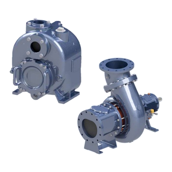
- Page 2 Solid Waste Pump FOREWORD These units are horizontal solid waste handling pumps identified by Ruhrpumpen as SWP. They are designed for continuous duty and solid handling. It is recommended that the services of a Ruhrpumpen installation technician be employed for the installation and initial starting of the pump.
- Page 3 Solid Waste Pump Information in this manual is believed to be reliable, but it is not guaranteed by Ruhrpumpen as to its completeness or accuracy. © 2023 Ruhrpumpen All Rights Reserved V8.122123...
-
Page 4: Table Of Contents
Solid Waste Pump INDEX 1. PRODUCT DESCRIPTION ........................8 1.1 INTRODUCTION ..........................8 1.2 PUMP CASE AND IMPELLER ......................9 1.2.1 Pump Case ..........................9 1.2.2 Impeller ............................ 9 1.3 SEAL CHAMBER ..........................9 1.4 BEARING FRAME ..........................9 2. SAFETY..............................10 2.1 IDENTIFICATION OF SAFETY INSTRUCTIONS IN THE OPERATING MANUAL ......... - Page 5 Solid Waste Pump 4.3.1 Equipment/Material Required ....................32 4.3.2 Grouting Precautions......................32 4.3.3 Grouting Procedure ........................ 33 4.4 ANCHOR TIGHTENING TORQUE SELECTION ................. 35 4.5 BAND AND PULLEY SYSTEM INSTALLATION .................. 36 4.6 AUXILIARY CONNECTIONS ......................36 4.7 ELECTRICAL CONNECTIONS ......................36 4.8 DIRECTION OF ROTATION CHECK ....................
- Page 6 8.1 DISASSEMBLY ..........................71 8.1.1 Disassembly of Pump Sizes 2x2, 3x3, 4x4, 6x6, 8x8, 10x10 and 12x10 ........72 8.1.2 Disassembly of SWP 2X2 Special Priming Connection ............74 8.1.3 Disassembly of Pump Size 12x12 ................... 75 8.2 INSPECTION AND CLEANING ......................77 8.3 REASSEMBLY ..........................
- Page 7 Solid Waste Pump 10. PARTS INFORMATION ........................145 10.1 PUMP SIZES 2X2, 3X3, 4X4, 6X6, 8X8, 10X10 and 12X10 ............145 10.1.1 Pump Assembly ........................145 10.1.2 Rotor Assembly ........................147 10.1.3 Flap Valve Assembly ......................149 10.2 PUMP SIZE 12X12 ........................151 11.
-
Page 8: Product Description
Ruhrpumpen recommends consulting also API Recommended Practices 686 to ensure proper installation in your facility. Please contact a Ruhrpumpen representative should problems arise. The pump may only be opened by a Ruhrpumpen approved technician during the guarantee period. In case of queries, please have your project number and type designation of the pump available. You can find both of these on the first page of these operating instructions or on the rating plate fixed to the pump. -
Page 9: Pump Case And Impeller
Solid Waste Pump A spacer coupling is provided for accessibility of service and maintenance. The spacer permits back pull-out, which allows the removal of the rotating element without disturbing the piping or driver. The following information is included in the nameplate of your pump unit: •... -
Page 10: Safety
Solid Waste Pump 2. SAFETY This operation manual gives basic instructions that should be observed during installation, operation and maintenance of the pump. It is therefore imperative that this manual be read by the responsible personnel/operator prior to assembly and commissioning. It must always be kept available at the installation site. -
Page 11: Qualification And Training Of Operating Personnel
If the staff does not have the necessary knowledge, they must be trained and instructed. Training may be performed by a Ruhrpumpen representative on behalf of the plant operator. Moreover, the plant operator is to make sure that the contents of the operating manual are fully understood by the personnel. -
Page 12: Safety Instructions Relevant For Operation
Solid Waste Pump 2.5 SAFETY INSTRUCTIONS RELEVANT FOR OPERATION WARNING If hot or cold machine components are exposed, they can create a hazard and must be guarded against accidental contact (attach warning signs). WARNING Guards for moving parts (e.g. coupling) must not be removed from the machine while in operation (mounting &... -
Page 13: Unauthorized Alterations And Spare Parts
Modifications may be made to the machine only after consultation with a Ruhrpumpen representative. Using spare parts and accessories authorized by Ruhrpumpen is in the interest of safety. The use of parts not authorized by the dealer exempt the manufacturer from any liability, voiding the warranty. -
Page 14: Transport & Storage
The pump, coupling hub, and driver are optionally shipped mounted on the baseplate. ATTENTION If you choose to order a pump without its baseplate, a Ruhrpumpen technician will be required to supervise the pump’s installation and leveling on-site to prevent voiding the warranty. -
Page 15: Transport
Solid Waste Pump 3.3 TRANSPORT ATTENTION The electric motor may be provided with a lifting eye, this lifting eye is intended only for the purpose of carrying out service activities to the electric motor only. NEVER lift a complete pump unit at the lifting eye of an electric motor. DANGER The pump (set) could overbalance and fall. - Page 16 Solid Waste Pump CAUTION When transporting with a crane, the rope should be slung round the unit as shown in the figure below. CAUTION The rope should not be slung around the lugs attached to the motor or around the lugs attached to the pump.
-
Page 17: Storing
Solid Waste Pump 3.4 STORING CAUTION Damage during storage due to liquid ingress, humidity, dirt or vermin. Corrosion/contamination of the pump (set). • Clean and cover pump apertures and connections as required prior to putting the pump into storage. • For outdoor storage cover the pump (set) or the packaged pump system and accessories with weatherproof material. - Page 18 When the pump is to be installed, remove all the protective coatings and desiccant or drain all oils. One month before installation, a Ruhrpumpen representative should be employed to conduct a final inspection. To properly store the motor (driver) for periods longer than one month, follow these steps: Store the motor in a clean, dry area, or cover it with a loose tarp (the tarp must be loose in order to prevent condensation).
- Page 19 Solid Waste Pump ATTENTION Follow the instruction manual of the driver manufacturer to ensure correct lubrication. Upon receipt, considering that the oil-lubricated drivers are not shipped oil-filled, fill the reservoir to maximum level with properly selected oil with rust and corrosion inhibitors. ATTENTION Always drain the oil before moving the pump, to avoid any damage, and refill once the unit has been re-sited.
- Page 20 Solid Waste Pump Motors, which have been subjected to vibration, must be disassembled and each bearing inspected for damage. Oil or grease must be completely changed using lubricants and methods recommended on the motor's lubrication plate, in the “LUBRICATION” section of the driver manufacturer’s manual.
-
Page 21: Conservation
Solid Waste Pump After the storing period, follow the next steps as start-up preparations: Motor should be thoroughly inspected and cleaned to restore to an “As Shipped” condition. Motors, which have been subjected to vibration, must be disassembled and each bearing inspected for damage. -
Page 22: Disposal
Solid Waste Pump 3.6 DISPOSAL DANGER Mishandling and improper disposal of hot, toxic, or other harmful substances. Hazard to people and the environment. • Collect and properly dispose of flushing fluids and any fluid residues. • Wear safety clothing and a protective face mask. •... - Page 23 Solid Waste Pump IMPORTANT The abandonment in the environment of the apparatus or the illegal disposal of the same is punished by law. WARNING Waste electrical equipment/consumables/supplies pose a health and environmental hazard. Hazard to people and the environment. • Collect, segregate, and properly dispose of electrical and electronic components.
-
Page 24: Inspection
Solid Waste Pump 3.7 INSPECTION DANGER Magnetic impact on personal health. Danger to life. • Never permit people to come in contact with Electro-Magnetic devices like motors, variable frequency drives, and magnetic drive assemblies who may have personal risks that can be impacted (e.g. pace-makers). •... -
Page 25: Installation
Solid Waste Pump 4. INSTALLATION CAUTION Mishandling and improper installation of inflammable, toxic, or other substances that harmful. Danger to life and the environment. • Installation, foundation and maintenance of pumps handling inflammable liquids and other pollutive products may only be performed by authorized companies or their personnel. - Page 26 Solid Waste Pump WARNING Unsecure installation on surfaces which are unsuitable for support the static and dynamic loads. Personal injury and damage to property. • Use concrete with compressive strength class C12/15 which meets the requirements of exposure class X0 to EN 206-1. •...
- Page 27 Correct and orderly installation/assembly is necessary for trouble-free operation of the unit. Ruhrpumpen does assume liability damage resulting from inadequate installation/assembly. The chosen location for installation must offer enough space for maintenance activities. Ruhrpumpen recommends consulting also API Recommended Practice 686 to ensure proper installation in your facility. V8.122123...
-
Page 28: Concrete Foundation Preparation
API Recommended Practices 686. ATTENTION The design of foundations is not responsibility of Ruhrpumpen. It is therefore recommended that the customer consult a competent specialist skilled in the field of foundations, to insure proper design/installation of the foundation. - Page 29 Solid Waste Pump Figure 4.1 Imaginary lines Build foundation approximately 3 inches (76 mm) larger overall than the pump baseplate for machines up to 500 horsepower (372 kW), and 6 inches (152 mm) larger for machines greater than 500 horsepower (372 kW) to provide ample anchorage for the foundation bolts.
-
Page 30: Leveling Baseplate
Solid Waste Pump Use a template to accurately locate foundation bolts according to the General Arrangement. Choose foundation bolts of size specified in drawing (ASTM A36, M 1020 and ASTM A575 are recommended), they should be long enough to allow a minimum of two threads above the nuts. - Page 31 Solid Waste Pump ATTENTION There should be a minimum annular clearance of 1/8 inch (3 mm) between anchor bolt holes and the anchor bolts to allow for field alignments. DANGER Exercise proper caution when working under or around suspended objects. Using a precision level across baseplate pads, adjust jacking bolts as necessary to ensure that baseplate is level in all directions (See Figure 4.2), within 0.002 in/ft (0.2 mm/m).
-
Page 32: Grouting
Solid Waste Pump NOTE Each jacking bolt should have a mounting pad, to distribute the stresses evenly. NOTE The baseplate should be mounted without distortion. Under no circumstances should the driver be higher than the pump. When baseplate is level, 'snug' the foundation bolt nuts, but do not tighten completely. 4.3 GROUTING* NOTE The information included in this section is intended as a general guideline. -
Page 33: Grouting Procedure
Solid Waste Pump 4.3.3 Grouting Procedure Verify that anchored bolt sleeves are clean and dry. Fill them with a nonbonding moldable material to prevent them from being grouted. The anchor bolt threads should be protected with tape before grouting. Provide a form around the baseplate to contain the grout. The form should be chamfered at all corners. - Page 34 Solid Waste Pump Tap baseplate to eliminate air pockets. ATTENTION It is imperative to get rid of all trapped air before the grout hardens. ATTENTION Check frequently for grout leaks. ATTENTION Leaks will not self-seal and may cause voids. Remove jackscrews and grout-forms once the grout has completely hardened (takes around 3 days).
-
Page 35: Anchor Tightening Torque Selection
Solid Waste Pump 4.4 ANCHOR TIGHTENING TORQUE SELECTION To appropriately select an anchor tightening torque, follow this procedure: ATTENTION Prior to selecting a tightening torque, the nut and anchor material and their respective yield strengths must be known. 1. Compare the maximum yield strength of the nut and anchor pair that will be tightened and choose the lower value. -
Page 36: Band And Pulley System Installation
Solid Waste Pump 4.5 BAND AND PULLEY SYSTEM INSTALLATION Make sure that the power source and the pump are parallel to each other. Use a ruler along the sides of the pulleys to ensure that they are properly aligned. On systems that use two or more pulleys, make sure that the bands are the same. Usage of different bands will lead to their accelerated wear. -
Page 37: Direction Of Rotation Check
Solid Waste Pump CAUTION Excessive time between star and delta switch-over on three-phase motors during start-up takes too long. Damage to the pump (set). • Optimize switch-over period between star and delta. • Install motor overload protection. 4.8 DIRECTION OF ROTATION CHECK WARNING Trapped hands &... - Page 38 Solid Waste Pump CAUTION Excessive coupling misalignment. Damage to the pump. • Always check and align motor and coupling element(s) before starting the pump. • Follow the coupling alignment limits given in this installation operating and maintenance manual. • Prepare an inspection & maintenance schedule with special emphasis on coupling alignment.
-
Page 39: Piping And Alignment
Solid Waste Pump 5. PIPING AND ALIGNMENT DANGER Excessive loads acting on the pump nozzles/flanges. Danger to life from leakage of hot, toxic, corrosive or flammable fluids. • Always ensure that surrounding pipe-work is aligned to the pump without strain. •... -
Page 40: Piping The System
Solid Waste Pump WARNING Do not start the piping and alignment procedures until grouting, preliminary alignment (as seen in the previous sections of this manual) and on site welding have been performed. ATTENTION In a new installation, great care should be taken to prevent dirt, scale, welding beads, and other items from entering the pump. - Page 41 Solid Waste Pump ATTENTION The design of piping and related systems is not the responsibility of Ruhrpumpen. It is, therefore recommended that the customer consult a competent specialist skilled in the field of piping to insure proper design/installation of all the piping.
- Page 42 Solid Waste Pump Figure 5.1 Correct mounting of a cone type strainer. Disconnect the piping from the pump if you heat one side of the pipe to align the pipe to the pump. Pump and pipe flanges must be parallel; they should mate together without effort, and with the bolt holes properly in line.
- Page 43 Solid Waste Pump ATTENTION In horizontal suction lines, reducers should be eccentric (with the flat side of the reducer on top). ATTENTION No obstruction within at least five pipe diameters of the suction flange should be fitted. ATTENTION Do not install unsupported piping on the pump. ATTENTION Make sure electrical connections do not impose any stress on the pump unit.
-
Page 44: Alignment
Solid Waste Pump 5.2 ALIGNMENT IMPORTANT It is recommended to generally establish a maximum misalignment of 0.005” [0.127mm]. It is important to note that as the misalignment tolerance increases, the risk to the pumping equipment increases. Possible problems resulting from poor alignment could negatively affect the performance and durability of the equipment. - Page 45 Solid Waste Pump 3. Thermal Growth If there are thermal growth considerations on the piece of equipment, it is a good idea to get these numbers so that they can be added to or subtracted from the graphical solution before the equipment move is made, this is known as “Hot alignment”.
- Page 46 Solid Waste Pump Figure 5.2 Example for reverse indicator graphical analysis. The next step is to determine indicator sag. Set up your bracket arrangement on a pipe. Set the indicator at '0' on top. Roll set up until indicator is at the bottom of pipe. It will read negative. In this example, it is found to be -0.005 inch (-0.127 mm).
- Page 47 Solid Waste Pump Figure 5.3 Indicator sag. With the indicator bracket attached to the motor hub reading off the pump hub, rotate unit in 90° increments and take readings. Bottom reading is then corrected for indicator sag. Indicator sag in the example was determined to be -0.005 inch (-0.127 mm).
- Page 48 Solid Waste Pump Figure 5.4 Motor shaft extension relative to the pump shaft center line. Now with the indicator bracket attached to the pump hub reading off the motor hub, rotate unit again in 90° increments. NOTE If you can set up both indicators at once, both sets of readings can be taken at one time. Bottom reading is then corrected for indicator sag.
- Page 49 Solid Waste Pump Figure 5.5 T.I.R. second reading We have now located the motor shaft theoretical extension in two places: A. In the plane of the pump hub. B. In the plane of the motor hub. Drawing a straight line through these two points crossing the plane of the two motor feet. The shim adjustment can now be read directly off the graph.
- Page 50 Solid Waste Pump C. REVERSE INDICATOR ALIGNMENT MORE THAN TWO UNITS GRAPHICAL ANALYSIS This method lends itself very well in solving alignment problems of three or more pieces of equipment in a line. To solve this problem, follow the steps already outlined for each coupling in the train. Plot the shaft to shaft relationship of each set of shafts.
- Page 51 Solid Waste Pump Figure 5.8 Across the disc pack alignment graphical analysis example. The next step is to determine indicator sag. Set up your bracket arrangement on a pipe. Set the indicator at '0' on top. Roll set up until indicator is at the bottom of pipe. It will read negative. In this example, it was found to be -0.004 inch (-0.102 mm).
- Page 52 Solid Waste Pump Bottom reading is then corrected for indicator sag. The indicator sag in the example was determined to be -0.004 inch (-0.102 mm). The -0.004 inch (-0.102 mm) was subtracted from -0.025 inch (- 0.635 mm) indicator reading to give an actual of -0.020 inch (-0.508 mm) reading. As this is a TIR (Total Indicator Reading) it is two times the actual center member center line location relative to the pump shaft extension or -0.020 inch (-0.508 mm) / 2 inches (50.8 mm) = -0.010 inch (0.254 mm).
- Page 53 Solid Waste Pump The minus reading on the bottom indicates that the center member tips up as it extends away from the motor. Using a scale of one small division on the graph equals 0.001 inch (0.025 mm), plot the 0.006 inch (0.192 mm) as shown on the example.
-
Page 54: Lubrication
Oil level should be determined by using the sight glasses in the bearing cover. ATTENTION Ruhrpumpen takes every precaution during our assembly process and subsequent final assembly audits to ensure no bearing bracket oil leaks exist prior to shipment. Oil can leak past the lip seal in an “overfill”... -
Page 55: Quantity
Solid Waste Pump 6.1.3 Quantity The oil capacity required for the mechanical seal and bearings is contained in the following table: MECHANICAL SEAL BEARING BRACKET PUMP SIZE [ liters] [ quarts (US gallons)] [ liters] [ quarts (US gallons)] 2 x 2 0.42 0.53 3 x 3... - Page 56 Solid Waste Pump ATTENTION Only change the oil when the machine is switched off. ATTENTION The drained oil is hot, and can cause severe burns. ATTENTION Remember that oil level should be determined by using sight glass in bearing bracket. Oil level in constant level oiler does not correspond to oil level in bearing bracket.
-
Page 57: Operation
Solid Waste Pump 7. OPERATION IMPORTANT NEVER operate the pump in a system or under system conditions (flow, pressure, temperature, etc.) for which it has not been designed. NOTE The electric motor and drive assembly is a sub-component of the pump (set) with its own installation, operating, and maintenance guidelines. -
Page 58: Priming
Never close the Isolation valve(s) in the suction line and/or supply line during pump operation. The SWP process pump can be manually or automatically primed during its first operation. Please follow the next steps to prime the pump depending on the method to be used. -
Page 59: Startup
Solid Waste Pump 7.2 STARTUP DANGER Abnormal noise, vibration, temperature or leakage. Damage to the pump. • Switch off the pump (set) immediately. • Eliminate the causes before returning the pump set to service. • Prepare an inspection & maintenance schedule with special emphasis on abnormal noise, vibration, and leakage. -
Page 60: Startup Frequency
Solid Waste Pump ATTENTION Immediately observe the pressure gauges. If the discharge pressure is not quickly attained, stop the driver, re-prime and attempt to restart. Adjust the discharge valve until rated flow is obtained. ATTENTION A sudden increase of running noise is always a sign of possible trouble. ATTENTION If shaft rotation is incorrect, consult the driver manufacturer´s instructions in order to change rotation. -
Page 61: Safety Devices
Solid Waste Pump 7.2.2 Safety Devices ATTENTION All safety devices for temperature, vibration, leakage etc., must be properly connected to their respective motor circuit control panel before start-up. Consider special descriptions and wiring diagrams. 7.2.3 Initial Startup WARNING Every time, before the pump is started up, the safety devices must be mounted and fastened. WARNING In order to avoid risks of injury or damage, all pump units must be equipped with emergency- stop devices. - Page 62 Solid Waste Pump Figure 7.1. Seal setting devices. The initial startup procedure is as follows: Before starting the pump, check the security of all bolting, piping, and wiring. Check all gauges, valves and instruments for proper working order. Check all equipment for proper lubrication and correct rotation. Verify that the discharge valve is closed.
-
Page 63: Regular Startup
Solid Waste Pump DANGER Do not allow discharge valve to remain closed for any length of time. Pumped fluid temperature will rise excessively causing damage to pump. 7.2.4 Regular Startup The startup procedure is as follows: Before starting the pump makes sure the oil levels are above the low and below the high marks on the sight glasses. - Page 64 Solid Waste Pump Ruhrpumpen recommends checking the pump constantly at regular intervals in order to detect problems early, in case they arise. The operational check routine must include minimum the following points: CAUTION Beware of freely rotating parts, when the pump is in operation there is a high risk of injury.
-
Page 65: Doweling (Optional)
Solid Waste Pump ATTENTION If the sealing system of the mechanical seal fails, the pump must be taken out of operation immediately. DANGER The pump may only be operated under the minimum operating range for short periods. The minimum pump flow is given in the characteristic line. For pumps with equipped with packing strips as a sealing option, do not tighten the packing strips excessively to the point of stopping the leakage. -
Page 66: Stopping
Solid Waste Pump 7.5 STOPPING Throttle pump discharge to minimum flow. WARNING DO NOT close suction valve, this will cause the pump to run dry. Turn the power off to the driver. Close the pump discharge valve Observe the run - down of the pump until full stop. ATTENTION If the rotor is jerky or suddenly stops, there is a danger that the rotor has become blocked. -
Page 67: Shutdown
Solid Waste Pump 7.6 SHUTDOWN CAUTION Heat build-up inside the pump. Damage to the shaft seal. • Thermal installations require sufficient post run time – with the heating/chilling source switched off. This is until the pumped fluid handled has normalized to ambient temperature. -
Page 68: Stuck Impeller Shutdown
Solid Waste Pump a. If the plant is in an operational state, warm up and start the unit at monthly intervals (see SECTION 7.2 - STARTUP for details). b. If the plant is not in an operational state, turn the unit over by hand a couple of times at monthly intervals, ensuring the shaft is not returned to the same position, to allow the bearings to rest in a different position every time. -
Page 69: Ambient Temperature
Solid Waste Pump 7.7 AMBIENT TEMPERATURE CAUTION Operation outside the permissible ambient temperature. Damage to the pump and motor. • Observe the specified pump (set) and auxiliary device limits for permissible ambient temperatures. • Always use motors that are suitable for the atmospheric humidity conditions. 7.8 FLUIDS BEING HANDLED CAUTION Excessively high density fluids being handled. -
Page 70: Maintenance
If the complete disassembly of the pump is not necessary, use only the required steps. To perform the maintenance of the SWP pump, no special (custom made) tools are needed. CAUTION Mishandling and improper installation of inflammable, toxic, or other substances that are harmful. -
Page 71: Disassembly
ATTENTION For any component/accessory that has not been manufactured by Ruhrpumpen and is part of the pump´s equipment, a complete reading of said component/accessory manufacturer´s manual must be carried out for further information on proper maintenance procedures and relevant safety warnings. -
Page 72: Disassembly Of Pump Sizes 2X2, 3X3, 4X4, 6X6, 8X8, 10X10 And 12X10
Remove the plugs from the top of the case. If your pump is equipped with a special priming connection, refer to Section 8.1.2 Disassembly of SWP 2x2 special priming option, if it is equipped with a threaded priming connection, continue with step 11. - Page 73 Solid Waste Pump Remove the corresponding bolt that secures the flap valve to the suction flange. Remove the flap valve from the suction flange. Untighten and remove the corresponding bolts that secure the cover plate to the case. Remove the cover plate from the casing. Untighten and remove the corresponding nuts that secure the wear plate to the cover plate.
-
Page 74: Disassembly Of Swp 2X2 Special Priming Connection
Using a bearing extractor, remove the thrust (axial) bearing from the shaft. Using a bearing extractor, remove the radial bearing from the shaft. 8.1.2 Disassembly of SWP 2X2 Special Priming Connection Remove the screw from the retaining clamp. Untighten and remove the bolts that secure the retaining clamp to the priming plug. -
Page 75: Disassembly Of Pump Size 12X12
Solid Waste Pump 8.1.3 Disassembly of Pump Size 12x12 Stop the pump. See SECTION 7.5 – STOPPING. Drain all possible fluids from the pump case. Disconnect any auxiliary piping and wiring that could interfere with disassembly. Disconnect the driver-to-pump coupling and remove coupling spacer. When disassembling the pump, match mark, tag or otherwise identify all parts, and provide separate containers for small parts. - Page 76 Solid Waste Pump Remove the impeller from the shaft. Remove the impeller wear ring. Remove the gasket from the case cover. Remove the gasket from the shaft. Remove the mechanical seal from the shaft. Remove the plugs from case cover. Remove the constant level oiler from the coupling side case cover.
-
Page 77: Inspection And Cleaning
Inspect all components for corrosion, erosion, pitting, and scoring. If required, replace with Ruhrpumpen O.E.M. genuine replacement parts. a. Visual check all individual parts for any damage b. Check the casing for wear. -
Page 78: Reassembly Of Pump Sizes 2X2, 3X3, 4X4, 6X6, 8X8, 10X10 And 12X10
Solid Waste Pump ATTENTION Any service performed on the pump´s interior must be performed by Ruhrpumpen personnel or one of its authorized representatives. Failing to comply with this will void the warranty and will release Ruhrpumpen and all its representatives of any liability. - Page 79 Solid Waste Pump Insert the thrust (axial) lip seal into the bearing bracket. Figure 8.3 Inserting the thrust (axial) lip seal into the bearing bracket. Insert the shaft assembly inside the bearing bracket. Figure 8.4 Inserting the shaft assembly inside the bearing bracket. V8.122123...
- Page 80 Solid Waste Pump Insert the radial lip seal over the shaft into the bearing bracket. Figure 8.5 Inserting the radial lip seal into the bearing bracket over the shaft. Insert the lip seal into the bearing cover. Figure 8.6 Inserting the lip seal into the bearing cover. Place the corresponding gasket on the bearing bracket.
- Page 81 Solid Waste Pump Place the bearing cover on the bearing bracket. Figure 8.8 Placing the bearing cover on the bearing bracket. Place the corresponding washers in their place on the bearing bracket. Figure 8.9 Placing the corresponding washers in their place on the bearing bracket. Place and tighten the corresponding screws to fasten the bearing cover to the bearing bracket.
- Page 82 Solid Waste Pump ATTENTION The tightening of the screws must be done in a crosswise pattern. Place the corresponding gasket on the bearing bracket´s radial side. Figure 8.11 Placing the corresponding gasket on the bearing bracket´s radial side. Position the seal chamber on the bearing bracket. Figure 8.12 Positioning the seal chamber on the bearing bracket.
- Page 83 Solid Waste Pump Place the corresponding washers on the bearing bracket. Figure 8.13 Placing the corresponding washers on the bearing bracket. Place and tighten the corresponding screws to secure the seal chamber to the bearing bracket. Figure 8.14 Placing and tightening the corresponding screws to secure the seal chamber to the bearing bracket.
- Page 84 Solid Waste Pump Place enough shims on the shaft to obtain the desired clearance between the impeller and the wear plate. Figure 8.16 Placing shims on the shaft to obtain the desired clearance between the impeller and the wear plate. Insert the impeller over the shaft.
- Page 85 Solid Waste Pump Place the impeller washer in its position on the impeller. Figure 8.18 Placing the impeller washer in its position on the impeller. Place and tighten the impeller locknut to lock the impeller in its position. Figure 8.19 Placing and tightening the impeller locknut to lock the impeller in its position. Place and tighten the corresponding oil sights in their positions on the bearing bracket.
- Page 86 Solid Waste Pump Place and tighten the corresponding NPT plugs on the bearing bracket. Figure 8.21 Placing and tightening the corresponding NPT plugs on the bearing bracket. Place and tighten the corresponding screw on the bearing bracket. Figure 8.22 Placing and tightening the corresponding screw on the bearing bracket. Place and tighten the NPT plugs on the bearing bracket.
- Page 87 Solid Waste Pump Place and tighten the first breather on the bearing bracket. Figure 8.24 Placing and tightening the first breather on the bearing bracket. Place and tighten the second breather on the bearing bracket. Figure 8.25 Placing and tightening the second breather on the bearing bracket. Place the O-ring seal in its position on the bearing bracket.
- Page 88 Solid Waste Pump Once the rotor is completely assembled, insert it inside the casing. Figure 8.27 Inserting the rotor assembly inside the casing. Place the corresponding washers on the rotor assembly before screwing it to the casing. Figure 8.28 Placing the corresponding washers on the rotor assembly before screwing it to the casing. Place and tighten the corresponding screws to secure the rotor assembly to the casing.
- Page 89 Solid Waste Pump Insert the deflector over the shaft. Figure 8.30 Inserting the deflector over the shaft. Place and tighten the corresponding nuts to secure the deflector in place. Figure 8.31 Placing and tightening the corresponding nuts to secure the deflector in place. V8.122123...
- Page 90 Solid Waste Pump Place the corresponding O-rings on the cover plate. Figure 8.32 Placing the corresponding O-rings on the cover plate. Place the wear plate on the cover plate. Figure 8.33 Placing the wear plate on the cover plate. V8.122123...
- Page 91 Solid Waste Pump Place and tighten the corresponding nuts to secure the wear plate to the cover plate Figure 8.34 Placing and tightening the corresponding nuts to secure the wear plate to the cover plate. Insert the cover plate assembly inside the casing. Figure 8.35 Inserting the cover plate assembly inside the casing.
- Page 92 Solid Waste Pump Place and tighten the corresponding hex bolts to secure the cover plate assembly to the casing. Figure 8.36 Placing and tightening the corresponding hex bolts to secure the cover plate assembly to the casing. Place the flap valve on the suction flange. Figure 8.37 Placing the flap valve on the suction flange.
- Page 93 Solid Waste Pump Place the corresponding bolt to secure the flap valve to the suction flange. Figure 8.38 Placing the corresponding bolt to secure the flap valve to the suction flange. Place the corresponding gasket on the case suction. Figure 8.39 Placing the corresponding gasket on the case suction. V8.122123...
- Page 94 Solid Waste Pump Place the suction flange on the casing. Figure 8.40 Placing the suction flange on the casing. Place the corresponding washers on the suction flange. Figure 8.41 Placing the corresponding washers on the suction flange. Place and tighten the corresponding bolts to secure the suction flange to the casing. Figure 8.42 Placing and tightening the corresponding bolts to secure the suction flange to the casing.
- Page 95 Solid Waste Pump Place the corresponding gasket on the case discharge. Figure 8.43 Placing the corresponding gasket on the case discharge. Place the discharge flange on the case. Figure 8.44 Placing the discharge flange on the case. V8.122123...
- Page 96 Figure 8.46 Placing and tightening the corresponding bolts to secure the discharge flange to the case. If your pump is equipped with a special priming connection, refer to Section 8.3.3 SWP 2X2 Special Priming Connection, if it is equipped with a threaded priming connection, continue with step 48 V8.122123...
- Page 97 Solid Waste Pump Place and tighten the top case plug on the case. Figure 8.47 Placing and tightening the top case plug on the case. Place the corresponding plugs on the top of the case. Figure 8.48 Placing the corresponding plugs on the top of the case. V8.122123...
- Page 98 Solid Waste Pump Place the corresponding plug on the suction flange. Figure 8.49 Placing the corresponding plug on the suction flange. Place the drain plug on the case. Figure 8.50 Placing the drain plug on the case. V8.122123...
- Page 99 Solid Waste Pump Place the spring valve on the case. Figure 8.51 Placing the spring valve on the case. V8.122123...
- Page 100 Solid Waste Pump SWP pump assembly is complete. Figure 8.52 Complete SWP pump assembly. V8.122123...
-
Page 101: Reassembly Of Pump Size 12X12
Solid Waste Pump 8.3.2 Reassembly of Pump Size 12x12 Insert the radial bearing on the shaft. Figure 8.53 Inserting the radial bearing on the shaft. Insert the axial bearing on the shaft. Figure 8.54 Inserting the axial bearing on the shaft. V8.122123... - Page 102 Solid Waste Pump Insert the bearing lock washer over the shaft until it reaches the axial bearing. Figure 8.55 Inserting the bearing lock washer over the shaft until it reaches the axial bearing. ATTENTION Make sure that the tab on the inner diameter of the bearing lock washer matches the corresponding groove on the shaft.
- Page 103 Solid Waste Pump Bend one of the tabs on the bearing lock washer towards one of the grooves on the bearing lock nut to fix them together. Insert the rotor assembly inside the bearing housing from the coupling side. Figure 8.57 Inserting the rotor assembly inside the bearing housing from the coupling side. Using an arbor press, insert the corresponding lip seal on the bearing housing axial cover.
- Page 104 Solid Waste Pump Insert the bearing housing axial cover over the shaft until it reaches the bearing housing. Figure 8.59 Inserting the bearing housing axial cover over the shaft until it reaches the bearing housing. Place and tighten the corresponding socket screws to secure the bearing housing axial cover to the bearing housing.
- Page 105 Solid Waste Pump Place the corresponding plugs on the bearing housing axial cover. Figure 8.61 Placing the corresponding plugs on the bearing housing axial cover. Using an arbor press, insert the corresponding lip seal on the bearing housing radial cover. Figure 8.62 Inserting the corresponding lip seal on the bearing housing radial cover.
- Page 106 Solid Waste Pump Insert the bearing housing radial cover over the shaft until it reaches the bearing housing. Figure 8.63 Inserting the bearing housing radial cover over the shaft until it reaches the bearing housing. Place and tighten the corresponding socket screws to secure the bearing housing radial cover to the bearing housing.
- Page 107 Solid Waste Pump Place the corresponding plugs on the bearing housing radial cover. Figure 8.65 Placing the corresponding plugs on the bearing housing radial cover. Insert the cooling coil inside the bearing housing. Figure 8.66 Inserting the cooling coil inside the bearing housing. V8.122123...
- Page 108 Solid Waste Pump Place the corresponding threaded tubes on the cooling coil. Figure 8.67 Placing the corresponding threaded tubes on the cooling coil. Place the corresponding drain plugs on the bearing housing. Figure 8.68 Placing the corresponding drain plugs on the bearing housing. V8.122123...
- Page 109 Solid Waste Pump Place the oil sight on the bearing housing. Figure 8.69 Placing the oil sight on the bearing housing. Place the constant level oiler on the bearing housing. Figure 8.70 Placing the constant level oiler on the bearing housing. V8.122123...
- Page 110 Solid Waste Pump Place the breather plug on the upper part of the bearing housing. Figure 8.71 Placing the breather plug on the upper part of the bearing housing. Place the corresponding plugs on the upper part of the bearing housing. Figure 8.72 Placing the corresponding plugs on the upper part of the bearing housing.
- Page 111 Solid Waste Pump Using an arbor press, insert the corresponding lip seal on the coupling side case cover. Figure 8.73 Inserting the corresponding lip seal on the coupling side case cover. Insert the case cover over the shaft until it reaches the bearing housing. Figure 8.74 Inserting the case cover over the shaft until it reaches the bearing housing.
- Page 112 Solid Waste Pump Place and tighten the corresponding hex bolts to secure the case cover to the bearing housing. Figure 8.75 Placing and tightening the corresponding hex bolts to secure the case cover to the bearing housing. Place the constant level oiler on the coupling side case cover. Figure 8.76 Placing the constant level oiler on the coupling side case cover.
- Page 113 Solid Waste Pump Place the corresponding plugs on the case cover. Figure 8.77 Placing the corresponding plugs on the case cover. Insert the mechanical seal over the shaft inside the case cover. Figure 8.78 Inserting the mechanical seal over the shaft inside the case cover. V8.122123...
- Page 114 Solid Waste Pump Place the corresponding gasket on the shaft. Figure 8.79 Placing the corresponding gasket on the shaft. Place the corresponding gasket on the case cover. Figure 8.80 Placing the corresponding gasket on the case cover. V8.122123...
- Page 115 Solid Waste Pump Insert the corresponding wear ring on the impeller. Figure 8.81 Inserting the corresponding wear ring on the impeller. Insert the impeller over the shaft until it reaches the gasket on the shaft. Figure 8.82 Inserting the impeller over the shaft until it reaches the gasket on the shaft. V8.122123...
- Page 116 Solid Waste Pump Place the corresponding studs on the front side of the case. Figure 8.83 Placing the corresponding studs on the front side of the case. Place and tighten the corresponding hex nuts on the studs on the front side of the case. Figure 8.84 Placing and tightening the corresponding hex nuts on the studs on the front side of the case.
- Page 117 Solid Waste Pump Place the case wear ring on the case. Figure 8.85 Placing the case wear ring on the case. Place the corresponding hex nuts to secure the case wear ring to the case. Figure 8.86 Placing the corresponding hex nuts to secure the case wear ring to the case. V8.122123...
- Page 118 Solid Waste Pump Insert the pump assembly inside the case from the coupling side. Figure 8.87 Inserting the pump assembly inside the case from the coupling side. Place the corresponding bolts to secure the pump assembly to the case. Figure 8.88 Placing the corresponding bolts to secure the pump assembly to the case. V8.122123...
- Page 119 Solid Waste Pump Place and tighten the corresponding hex nuts to fix the pump assembly to the case. Figure 8.89 Placing and tightening the corresponding hex nuts to fix the pump assembly to the case. Place the corresponding gasket on the suction cover. Figure 8.90 Placing the corresponding gasket on the suction cover.
- Page 120 Solid Waste Pump Place the suction flange on the suction cover. Figure 8.91 Placing the suction flange on the suction cover. Place and tighten the corresponding hex bolts to fix the suction flange to the suction cover. Figure 8.92 Placing and tightening the corresponding hex bolts to fix the suction flange to the suction cover. V8.122123...
- Page 121 Solid Waste Pump Place the case cover assembly on the case. Figure 8.93 Placing the case cover assembly on the case. Place the corresponding gasket on the upper part of the suction cover. Figure 8.94 Placing the corresponding gasket on the upper part of the suction cover. V8.122123...
- Page 122 Solid Waste Pump Place the upper cover on the gasket on the upper part of the suction cover. Figure 8.95 Placing the upper cover on the gasket on the upper part of the suction cover. Place and tighten the hex bolts to secure the upper cover to the suction cover. Figure 8.96 Placing and tightening the hex bolts to secure the upper cover to the suction cover.
- Page 123 Solid Waste Pump Place the corresponding gasket on the suction cover flange. Figure 8.97 Placing the corresponding gasket on the suction cover flange. Place the suction cover flange on the suction cover. Figure 8.98 Placing the suction cover flange on the suction cover. V8.122123...
- Page 124 Solid Waste Pump Place and tighten the corresponding socket screws to secure the suction cover flange to the suction cover. Figure 8.99 Placing and tightening the corresponding socket screws to secure the suction cover flange to the suction cover. Place the corresponding gasket on the case’s discharge. Figure 8.100 Placing the corresponding gasket on the case’s discharge.
- Page 125 Solid Waste Pump Place the discharge flange on the case’s discharge gasket. Figure 8.101 Placing the discharge flange on the case’s discharge gasket. Place the corresponding hex bolts to secure the discharge flange to the case’s discharge. Figure 8.102 Placing the corresponding hex bolts to secure the discharge flange to the case’s discharge. V8.122123...
- Page 126 Solid Waste Pump Place and tighten the hex nuts on the corresponding hex bolts to fix the discharge flange to the case’s discharge. Figure 8.103 Placing and tightening the hex nuts on the corresponding hex bolts to fix the discharge flange to the case’s discharge.
- Page 127 Solid Waste Pump SWP pump size 12x12 reassembly is complete. Figure 8.105 Complete reassembly of SWP pump size 12x12. V8.122123...
-
Page 128: Swp 2X2 Special Priming Connection Option
Solid Waste Pump 8.3.3 SWP 2X2 Special Priming Connection Place the corresponding gasket on the priming hole. Figure 8.106 Placing the corresponding gasket on the priming hole. Place the priming plug on the upper part of the case. Figure 8.107 Placing the priming plug on the upper part of the case. - Page 129 Solid Waste Pump Place the corresponding bolts on the retaining clamp. Figure 8.108 Placing the corresponding bolts on the retaining clamp. Tighten the bolts on the retaining clamp to fix it to the priming plug. Figure 8.109 Tightening the bolts on the retaining clamp to fix it to the priming plug. V8.122123...
- Page 130 Solid Waste Pump Place the retaining clamp screw on the retaining clamp. Figure 8.110 Placing the retaining clamp screw on the retaining clamp. Once these steps have been completed, refer to Section 8.3.1 Reassembly of Pump Sizes 2x2, 3x3, 4x4, 6x6, 8x8, 10x10 and 12x10, Step 49 to continue with the assembly procedure. V8.122123...
-
Page 131: Lip Seal Replacement
Solid Waste Pump 8.4 LIP SEAL REPLACEMENT 8.4.1 Lip Seal Extraction CAUTION Lip seals must be handled carefully. Mishandling of the lip seals can cause fractures and porosity which will lead to oil leaks during pump operation. CAUTION During installation of the lip seals, make sure that the lip seal is inserted in parallel. A crooked insertion of the lip seal may lead to oil leakage. -
Page 132: Lip Seal Replacement
Solid Waste Pump 8.4.2 Lip Seal Replacement 1. Before installing the thrust (axial) lip seal inside the bearing bracket, follow these steps: Lubricate the outside diameter of the lip seal with the lubricant provided by the manufacturer (grease is not recommended) or with P-80 rubber lubricant emulsion Lubricate the corresponding inside diameter of the bearing bracket. - Page 133 Solid Waste Pump 4. Insert the rotor inside the bearing bracket from the coupling side, as detailed in Section 8.3.1 – Reassembly of Pump Sizes 2x2, 3x3, 4x4, 6x6, 8x8, 10x10 and 12x10, step 4. 5. Before installing the radial lip seal inside the bearing bracket, follow these steps: Lubricate the outside diameter of the lip seal with the lubricant provided by the manufacturer (grease is not recommended) or with P-80 rubber lubricant emulsion...
- Page 134 Figure 8.116 Installing the bearing cover on the bearing bracket. 9. Refer to Section 8.3.1 – Reassembly of Pump Sizes 2x2, 3x3, 4x4, 6x6, 8x8, 10x10 and 12x10, step 9 and onwards to continue with the reassembly procedure of the SWP pump. V8.122123...
-
Page 135: Servicing
Solid Waste Pump 8.5 SERVICING WARNING Motor tipping. Risk of crushing hands and feet. • Suspend or support the motor to prevent it from tilting. WARNING Back pull-out unit tipping. Risk of squashing hands and feet. • Suspend or support the back pull-out unit at the pump end. IMPORTANT Flawed maintenance on the pump unit will result in shorter lifespan, possible break down and in any event loss of warranty. - Page 136 Solid Waste Pump CAUTION Burns. Injuries caused by burns. • Avoid introducing water into the terminal box of the electric motor when the pump room is sprayed clean. • NEVER spray water on hot pump parts. The sudden cooling down may cause them to burst and hot water may flow out.
-
Page 137: Inspection
Solid Waste Pump 8.5.2 Inspection WARNING Pump wear will reduce the hydraulic efficiency of the pump. Danger to the environment. • Regularly check the power being consumed and replace worn parts • Prepare an inspection & maintenance schedule with special emphasis on power consumption. - Page 138 Solid Waste Pump DANGER Magnetic impact on personal health. Danger to life. • Never permit people to come in contact with Electro-Magnetic devices like motors, variable frequency drives, and magnetic drive assemblies who may have personal risks that can be impacted (e.g. pace-makers). •...
-
Page 139: Dismantling
Solid Waste Pump NOTE All transmitting devices and radio equipment assemblies are sub-components of the pump (set) with their own installation, operating, and maintenance guidelines. All details can be found on nameplate(s) affixed to the device(s). Such devices have their own notified body approval, as indicated on the nameplate where applicable, and Conformity Risk Assessments. -
Page 140: Reassembly
Solid Waste Pump WARNING Inadequate preparation of work on the pump (set). Risk of injury. • Properly shut down the pump set, as stated in SECTION 7.6 - SHUTDOWN. • Close all isolation valves in the suction line and discharge line. •... -
Page 141: Returning Pump To Factory
ATTENTION All pumps returned to factory may be disassembled or maintained by RUHRPUMPEN service personnel only if the pumped liquid is clearly defined by the pump user. According to the "Decree for dangerous Goods", a safety data sheet DIN 52900 completely filled in must accompany the shipping documents. -
Page 142: Disposal
Solid Waste Pump 8.5.6 Disposal ATTENTION Make sure the used oil is discharged safely and no liquid or oil gets into the environment. NOTE All transmitting devices and radio equipment assemblies are sub-components of the pump (set) with their own installation, operating, and maintenance guidelines. All details can be found on nameplate(s) affixed to the device(s). -
Page 143: Spare Parts
The quantity of spare parts given in the following list is the minimum standard that must be had. Nonetheless, these quantities may vary depending on the individual working conditions. For more information, contact a Ruhrpumpen representative. Number of identical pumps (including reserve pumps) - Page 144 Solid Waste Pump Material Storage of spare parts • Store the spare parts in their original packaging. • Store in a dry place, preferably at a constant temperature. • Check the spare parts and the state of the packaging every 6 months for signs of corrosion. •...
-
Page 145: Parts Information
Solid Waste Pump 10. PARTS INFORMATION 10.1 PUMP SIZES 2X2, 3X3, 4X4, 6X6, 8X8, 10X10 AND 12X10 10.1.1 Pump Assembly Figure 10.1 – SWP Pump Sectional Drawing. V8.122123... - Page 146 Solid Waste Pump SWP Pump Assembly Sectional Drawing Parts List. ITEM DESCRIPTION ITEM DESCRIPTION CASING SPRING VALVE WEAR PLATE 900.1 HEX BOLT - UNC (REGULAR THREAD - INCH) COVER PLATE 900.2 HEX BOLT - UNC (REGULAR THREAD - INCH) ROTOR ASSEMBLY 900.3...
-
Page 147: Rotor Assembly
Solid Waste Pump 10.1.2 Rotor Assembly Figure 10.2 – SWP Rotor Sectional Drawing. V8.122123... - Page 148 Solid Waste Pump SWP Rotor Sectional Drawing Parts List. ITEM DESCRIPTION ITEM DESCRIPTION REGULAR HELICAL SPRING LOCK WASHERS SHAFT 554.1 (INCH SERIES) REGULAR HELICAL SPRING LOCK WASHERS IMPELLER 554.2 (INCH SERIES) REGULAR HELICAL SPRING LOCK WASHERS AXIAL BEARING 554.3 (INCH SERIES) RADIAL BEARING 554.4...
-
Page 149: Flap Valve Assembly
Solid Waste Pump 10.1.3 Flap Valve Assembly Figure 10.3 – SWP Flap Valve Sectional Drawing. V8.122123... - Page 150 Solid Waste Pump SWP Flap Valve Sectional Drawing Parts List. ITEM DESCRIPTION HELICAL SPRING LOCK WASHERS HEX BOLT - UNC (REGULAR THREAD - INCH) FLAP VALVE FLAP VALVE "A" V8.122123...
-
Page 151: Pump Size 12X12
Solid Waste Pump 10.2 PUMP SIZE 12X12 V8.122123... - Page 152 Solid Waste Pump SWP Pump Sectional Drawing. Figure 10.4 – V8.122123...
- Page 153 Solid Waste Pump SWP Pump Assembly Sectional Drawing Parts List. ITEM DESCRIPTION ITEM DESCRIPTION VOLUTE CASE RADIAL BALL BEARING SUCTION COVER ANGULAR CONTACT BEARING ROTOR ASSEMBLY BEARING HOUSING 400.1 DISCHARGE FLANGE GASKET RADIAL BEARING COVER 400.2 SUCTION COVER FLANGE GASKET AXIAL BEARING COVER 400.3...
- Page 154 Solid Waste Pump ITEM DESCRIPTION ITEM DESCRIPTION FEMALE THREADED COOLING COIL 901.6 HEX BOLT 721.4 TUBE 902.1 BOLT HEX SCREW 902.2 BOLT 912.1 DRAIN PLUG 920.1 912.2 DRAIN PLUG 920.2 912.3 DRAIN PLUG 920.3 914.1 SOCKET SCREW 920.4 914.2 SOCKET SCREW CASE COVER LOCK NUT SHAFT...
-
Page 155: Troubleshooting Chart
ATTENTION If the pump does not develop the required performance or if unexpected issue happens during start-up, please consider, before calling RUHRPUMPEN for assistance, please check carefully the pump´s environment. Check motor and pump speed in accordance with the labels, wire connections in the terminal box. Make sure that control devices are properly connected and measuring instruments are calibrated. - Page 156 Inner pump parts are a. Change worn parts. worn. b. Consult a Ruhrpumpen dealer. b. Density or viscosity of c. Apply correct voltage to the motor pumped fluid is not d. Check the cables, connections and fuses.
- Page 157 CAPACITY OR i. Formation of air j. Change worn parts. DISCHARGE pockets in the piping k. Consult a Ruhrpumpen dealer. PRESSURE LOW j. Inner pump parts are l. Apply correct voltage to the motor. worn m. Check the cables, connections and fuses.
-
Page 158: Extended Warranty
Fifteen days prior to the initial operation, a Ruhrpumpen Service Engineer must be hired by the customer to thoroughly inspect the pump to confirm that the pump is in a “as shipped” condition. This inspection must include, but not be limited to: a) Inspection of the preventative maintenance logs. -
Page 159: Pump Operation Log
Solid Waste Pump • The customer must send the equipment to an authorized Ruhrpumpen service center for maintenance every 48 months to replace all worn parts and so that a general inspection on the pump can be performed. Failure to comply with this will void the warranty. - Page 160 Solid Waste Pump CONDITION RECORDED ITEM YES NO VALUES When equipped with packing strips, the packing gland must not be overtightened. Packing gland tightening must be enough so that the pump does not experience splashing from the pumped liquid and so that the equipped drain is able to empty the drip pan.
-
Page 161: Annex A. Torque Tables
Solid Waste Pump ANNEX A. TORQUE TABLES A.1 METRIC TORQUE VALUES FOR PERMANENT JOINTS – COARSE THREAD (UNC) Yield Strength [MPa] Anchor Maximum Torque Maximum Torque Maximum Torque Maximum Torque Maximum Torque Maximum Torque Maximum Torque [N-m] [N-m] [N-m] [N-m] [N-m] [N-m] [N-m]... - Page 162 Solid Waste Pump Yield Strength 1025 1075 1125 [MPa] Maximum Torque Maximum Torque Maximum Torque Maximum Torque Maximum Torque Anchor [N-m] [N-m] [N-m] [N-m] [N-m] Size [ mm ] Lubricated Lubricated Lubricated Lubricated Lubricated 1053 1107 1161 1214 1361 1084 1435 1142 1509...
-
Page 163: Imperial Torque Values For Permanent Joints - Coarse Thread (Unc)
Solid Waste Pump A.2 IMPERIAL TORQUE VALUES FOR PERMANENT JOINTS – COARSE THREAD (UNC) Yield 32634 39885 47137 54389 61641 68893 76145 Strength [psi] Maximum Torque Maximum Torque Maximum Torque Maximum Torque Maximum Torque Maximum Torque Maximum Torque Anchor [lbf-ft] [lbf-ft] [lbf-ft] [lbf-ft]... - Page 164 Solid Waste Pump Yield Strength 134160 141412 148664 155916 163168 [psi] Maximum Torque Maximum Torque Maximum Torque Maximum Torque Maximum Torque Anchor [lbf-ft] [lbf-ft] [lbf-ft] [lbf-ft] [lbf-ft] Size [ in ] Lubricated Lubricated Lubricated Lubricated Lubricated 5/16 7/16 9/16 1050 1104 1157 1211...
-
Page 165: Metric Torque Values For Permanent Joints - Fine Thread (Unf)
Solid Waste Pump A.3 METRIC TORQUE VALUES FOR PERMANENT JOINTS – FINE THREAD (UNF) Yield Strength [MPa] Maximum Torque Maximum Torque Maximum Torque Maximum Torque Maximum Torque Maximum Torque Maximum Torque Anchor [N-m] [N-m] [N-m] [N-m] [N-m] [N-m] [N-m] Size [ mm ] Lubricated Lubricated... - Page 166 Solid Waste Pump Yield 1025 1075 1125 Strength [MPa] Maximum Torque Maximum Torque Maximum Torque Maximum Torque Maximum Torque Anchor [N-m] [N-m] [N-m] [N-m] [N-m] Size [ mm ] Lubricated Lubricated Lubricated Lubricated Lubricated 1053 1107 1161 1214 1361 1084 1435 1142 1509...
-
Page 167: Imperial Torque Values For Permanent Joints - Fine Thread (Unf)
Solid Waste Pump A.4 IMPERIAL TORQUE VALUES FOR PERMANENT JOINTS – FINE THREAD (UNF) Yield 32634 39885 47137 54389 61641 68893 76145 Strength [psi] Maximum Torque Maximum Torque Maximum Torque Maximum Torque Maximum Torque Maximum Torque Maximum Torque Anchor [lbf-ft] [lbf-ft] [lbf-ft] [lbf-ft]... - Page 168 Solid Waste Pump Yield 134160 141412 148664 155916 163168 Strength [psi] Maximum Torque Maximum Torque Maximum Torque Maximum Torque Maximum Torque Anchor [lbf-ft] [lbf-ft] [lbf-ft] [lbf-ft] [lbf-ft] Size [ in ] Lubricated Lubricated Lubricated Lubricated Lubricated 5/16 7/16 9/16 1099 1158 1218 1277...
-
Page 169: Metric Torque Values For Reusable Joints - Coarse Thread (Unc)
Solid Waste Pump A.5 METRIC TORQUE VALUES FOR REUSABLE JOINTS – COARSE THREAD (UNC) Yield Strength [MPa] Maximum Torque Maximum Torque Maximum Torque Maximum Torque Maximum Torque Maximum Torque Maximum Torque Anchor [N-m] [N-m] [N-m] [N-m] [N-m] [N-m] [N-m] Size [ mm ] Lubricated Lubricated... - Page 170 Solid Waste Pump Yield 1025 1075 1125 Strength [MPa] Maximum Torque Maximum Torque Maximum Torque Maximum Torque Maximum Torque Anchor [N-m] [N-m] [N-m] [N-m] [N-m] Size [ mm ] Lubricated Lubricated Lubricated Lubricated Lubricated 1012 1135 1196 1257 1001 1318 1049 1380 1098...
-
Page 171: Imperial Torque Values For Reusable Joints - Coarse Thread (Unc)
Solid Waste Pump A.6 IMPERIAL TORQUE VALUES FOR REUSABLE JOINTS – COARSE THREAD (UNC) Yield 32634 39885 47137 54389 61641 68893 76145 Strength [psi] Maximum Torque Maximum Torque Maximum Torque Maximum Torque Maximum Torque Maximum Torque Maximum Torque Anchor [lbf-ft] [lbf-ft] [lbf-ft] [lbf-ft]... - Page 172 Solid Waste Pump Yield Strength 134160 141412 148664 155916 163168 [psi] Maximum Torque Maximum Torque Maximum Torque Maximum Torque Maximum Torque Anchor [lbf-ft] [lbf-ft] [lbf-ft] [lbf-ft] [lbf-ft] Size [ in ] Lubricated Lubricated Lubricated Lubricated Lubricated 5/16 7/16 9/16 1009 1237 1304 1038...
-
Page 173: Metric Torque Values For Reusable Joints - Fine Thread (Unf)
Solid Waste Pump A.7 METRIC TORQUE VALUES FOR REUSABLE JOINTS – FINE THREAD (UNF) Yield Strength [MPa] Maximum Torque Maximum Torque Maximum Torque Maximum Torque Maximum Torque Maximum Torque Maximum Torque Anchor [N-m] [N-m] [N-m] [N-m] [N-m] [N-m] [N-m] Size [ mm ] Lubricated Lubricated... - Page 174 Solid Waste Pump Yield Strength 1025 1075 1125 [MPa] Maximum Torque Maximum Torque Maximum Torque Maximum Torque Maximum Torque Anchor [N-m] [N-m] [N-m] [N-m] [N-m] Size [ mm ] Lubricated Lubricated Lubricated Lubricated Lubricated 1053 1107 1161 1214 1361 1084 1435 1142 1509...
-
Page 175: Imperial Torque Values For Reusable Joints - Fine Thread (Unf)
Solid Waste Pump A.8 IMPERIAL TORQUE VALUES FOR REUSABLE JOINTS – FINE THREAD (UNF) Yield 32634 39885 47137 54389 61641 68893 76145 Strength [psi] Maximum Torque Maximum Torque Maximum Torque Maximum Torque Maximum Torque Maximum Torque Maximum Torque Anchor [lbf-ft] [lbf-ft] [lbf-ft] [lbf-ft]... - Page 176 Solid Waste Pump Yield Strength 134160 141412 148664 155916 163168 [psi] Maximum Torque Maximum Torque Maximum Torque Maximum Torque Maximum Torque Anchor Size [lbf-ft] [lbf-ft] [lbf-ft] [lbf-ft] [lbf-ft] [ in ] Lubricated Lubricated Lubricated Lubricated Lubricated 5/16 7/16 9/16 1099 1158 1218 1277...
- Page 177 +70 years creating the pumping technology that moves our world Ruhrpumpen is an innovative and efficient pump technology company that offers highly-engineered and standard pumping solutions for the oil & gas, power generation, industrial, water and chemical markets. We offer a broad range of centrifugal and reciprocating pumps that meet and exceed the requirements of the most demanding quality specifications and industry standards such as API, ANSI, UL, FM, ISO and Hydraulic Institute.
Need help?
Do you have a question about the SWP and is the answer not in the manual?
Questions and answers