Table of Contents
Advertisement
Quick Links
Advertisement
Table of Contents

Subscribe to Our Youtube Channel
Related Manuals for Ruhrpumpen HSD


Summary of Contents for Ruhrpumpen HSD
- Page 1 Installation, Operation and Maintenance Manual...
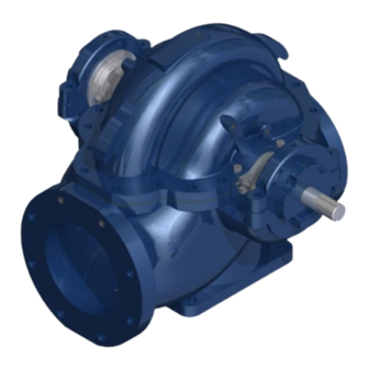
- Page 2 These units are horizontal split case centrifugal between bearings pumps and identified by Ruhrpumpen as HSD. It is recommended that the services of a Ruhrpumpen installation technician be employed for the installation and initial starting of the pump. Such service will help to ensure the user that the equipment is properly installed, and will provide an excellent opportunity for the plant operator to receive useful tips and guidelines relative to the unit.
- Page 3 Split Case, Centrifugal Pump Information in this manual is believed to be reliable, but it is not guaranteed by Ruhrpumpen as to its completeness or accuracy. © 2021 Ruhrpumpen All Rights Reserved. V3.041521...
-
Page 4: Table Of Contents
Split Case, Centrifugal Pump INDEX 1. PRODUCT DESCRIPTION ........................7 1.1 INTRODUCTION ..........................7 1.2 PUMP CASE, IMPELLER, AND WEAR RINGS ..................8 1.2.1 Pump Case ..........................8 1.2.2 Impeller and Wear Rings ......................8 1.3 BEARING HOUSING ......................... 8 1.4 LUBRICATION .......................... - Page 5 Split Case, Centrifugal Pump 4.3.2 Grouting Precautions......................32 4.3.3 Grouting Procedure ........................ 33 5. PIPING AND ALIGNMENT ........................37 5.1 PIPING THE SYSTEM ........................38 5.2 ALIGNMENT* ..........................41 6. LUBRICATION ............................51 6.1 GREASE LUBRICATED BEARINGS ....................51 6.1.1 Regular Grease Change ......................51 6.1.2.
- Page 6 7.6 SHORT-TERM SHUTDOWN ......................70 7.7 LONG-TERM SHUTDOWN......................70 8. MAINTENANCE ............................ 72 8.1 DISASSEMBLY ..........................74 8.1.1 HSD Disassembly Packing Strips Option ................. 74 8.1.2 HSD Disassembly Mechanical Seal Option ................75 8.2 INSPECTION AND CLEANING ......................76 8.3 REASSEMBLY ..........................76 8.3.1 HSD Packing Strips Option ......................
-
Page 7: Product Description
1.1 INTRODUCTION Ruhrpumpen pumps of type HSD are horizontal, single stage, double suction, single and double volute axially split case centrifugal pumps. These pumps are designed for continuous duty pumping of various fluids with combinations of metallurgical, mechanical, and installation features for application in fire service, cooling towers, municipal, sugar and paper Industry, pipeline, power generation, dewatering, mining, and water. -
Page 8: Pump Case, Impeller, And Wear Rings
Split Case, Centrifugal Pump These pumps rotation can be either clockwise or counterclockwise as viewed from the driver (coupling) end. The following information is included in the nameplate of your pump unit: Serial number RPM Head Capacity ... -
Page 9: Lubrication
Split Case, Centrifugal Pump 1.4 LUBRICATION Bearings in this pump may be lubricated by grease as standard and oil as an option. Grease lubricated pump bearings are prelubricated at the factory before shipment. Periodic inspection of bearing lubrication should be made and additional grease added as needed. Do not overgrease as this causes high bearing temperatures and shortens bearing life. -
Page 10: Safety
Split Case, Centrifugal Pump 2. SAFETY This operation manual gives basic instructions that should be observed during installation, operation and maintenance of the pump. It is therefore imperative that this manual be read by the responsible personnel/operator prior to assembly and commissioning. It must always be kept available at the installation site. -
Page 11: Qualification And Training Of Operating Personnel
If the staff does not have the necessary knowledge, they must be trained and instructed. Training may be performed by a Ruhrpumpen representative on behalf of the plant operator. Moreover, the plant operator is to make sure that the contents of the operating manual are fully understood by the personnel. -
Page 12: Safety Instructions Relevant For Operation
Modifications may be made to the machine only after consultation with a Ruhrpumpen representative. Using spare parts and accessories authorized by Ruhrpumpen is in the interest of safety. The use of parts not authorized by the dealer exempt the manufacturer from any liability, voiding the warranty. -
Page 13: Unauthorized Modes Of Operation
Split Case, Centrifugal Pump 2.8 UNAUTHORIZED MODES OF OPERATION The reliability of the machine is guaranteed if and only if it is used in the intended manner, in accordance with the statutes of this manual. The limit values specified in the data sheet must never be exceeded under any circumstance. -
Page 14: Transport & Storage
Ruhrpumpen during the quoting process, as this requires an analysis and design of a special, customized baseplate. If during the quoting process the customer fails to notify Ruhrpumpen the request that all components be forcibly mounted on the baseplate during shipment, Ruhrpumpen may ship all components mounted on the baseplate, prior written request from the customer, under the customer’s responsibility of the risks of deformation during transport. -
Page 15: Transport
2. Remove unit only by properly supporting the wooden shipping skid. 3. After unloading, inspect the pump, check the shipment against the packing list, and report damages or shortages immediately to freight carrier and to the designated Ruhrpumpen representative. CAUTION •... - Page 16 Split Case, Centrifugal Pump DANGER The pump (set) could overbalance and fall. Danger to life from falling parts! • When using a forklift always set the forks as far apart as possible and lift the package with both forks to prevent it from toppling over. •...
- Page 17 Split Case, Centrifugal Pump Figure 3.1a Correct position of the pump lifting – bare shaft pump only. Figure 3.1b Correct position of the lifting ropes or chains, side and non-drive end view. V3.041521...
-
Page 18: Storing
Split Case, Centrifugal Pump 3.4 STORING CAUTION Damage during storage due to Liquid ingress, humidity, dirt or vermin. Corrosion/contamination of the pump (set)! • Clean and cover pump apertures and connections as required prior to putting the pump into storage. •... - Page 19 14. When the pump is to be installed, remove all the protective coatings and desiccant or drain all oils. One month before installation, a Ruhrpumpen representative should be employed to conduct a final inspection. To properly store the motor (driver) for periods longer than one month, follow these steps: 1.
- Page 20 Split Case, Centrifugal Pump 4. Fill with lubricant the grease-lubricated cavities of the motor, but first remove the drain plug and fill the cavity until the grease starts to purge. CAUTION • Follow the instruction manual of the driver manufacturer to ensure that the lubrication is performed properly.
-
Page 21: Conservation
Split Case, Centrifugal Pump CAUTION • Be careful not to overheat, since keeping the temperature of the motor frame 9 °F (5 °C) above the surrounding ambient temperature is sufficient. After the storing period, follow the next steps as start-up preparations: 1. - Page 22 Split Case, Centrifugal Pump DANGER Mishandling and improper disposal of Hot, Toxic, or other Harmful substances Hazard to People and the Environment! • Collect and properly dispose of flushing fluids and any fluid residues. • Wear safety clothing and a protective face mask. •...
- Page 23 Split Case, Centrifugal Pump CAUTION Waste Electrical equipment/consumables/supplies pose a health and Environmental hazard. Hazard to people and the environment! • Collect, segregate, and properly dispose of electrical and electronic components. • Contact the manufacturer given on the corresponding nameplate for disposal and collection guidelines.
- Page 24 Split Case, Centrifugal Pump COMMENT • NOTE: All transmitting devices and Radio Equipment assemblies are sub- components of the pump (set) with their own installation, operating, and maintenance guidelines. All details can be found on name-plate(s) affixed to the device(s). Such devices have their own notified body approval, as indicated on the name-plate where applicable, and Conformity Risk Assessments.
-
Page 25: Installation
Split Case, Centrifugal Pump 4. INSTALLATION CAUTION Mishandling and improper installation of inflammable, Toxic, or other substances that harmful. Danger to Life and the Environment • Installation, foundation and maintenance of pumps handling inflammable liquids and other pollutive products may only be performed by authorized companies or their personnel. - Page 26 Split Case, Centrifugal Pump WARNING Unsecure installation on surfaces which are unsuitable for support the static and dynamic loads. Personal injury and damage to property! • Use concrete with compressive strength class C12/15 which meets the requirements of exposure class X0 to EN 206-1. •...
- Page 27 Correct and orderly installation/assembly is necessary for trouble-free operation of the unit. Ruhrpumpen does assume liability damage resulting from inadequate installation/assembly. The chosen location for installation must offer enough space for maintenance activities. Ruhrpumpen recommends consulting also API Recommended Practice 686 to ensure proper installation in your facility. V3.041521...
-
Page 28: Concrete Foundation Preparation
API Recommended Practices 686. IMPORTANT • The design of foundations is not the responsibility of Ruhrpumpen. It is therefore recommended that the customer consult a competent specialist skilled in the field of foundations, to insure proper design/installation of the foundation. - Page 29 Split Case, Centrifugal Pump 30° 30° Figure 4.1. Imaginary lines. 3. It is recommended to build foundation approximately 3 inches (76 mm) larger overall than the pump baseplate to provide ample anchorage for the foundation bolts. 3.1. Since water can accidentally flow in the floor, a height for the surface of the foundation of 4 inches (100 mm) at least above floor level is recommended.
-
Page 30: Leveling Baseplate
Split Case, Centrifugal Pump 4.2 LEVELING BASEPLATE NOTE • The information in this section is intended as a general guideline. For further information refer to the corresponding section in API Recommended Practices 686. Before leveling the unit onto the foundation, the following preparations must be made: 1. - Page 31 Split Case, Centrifugal Pump ATTENTION • Exercise proper caution when working under or around suspended objects. 6. If baseplate has preparation for jacking bolts, using a precision level across baseplate pads, adjust jacking bolts as necessary. Otherwise, adjust wedges (shim packs) as necessary using a precision level across baseplate pads.
-
Page 32: Grouting
Split Case, Centrifugal Pump NOTE • The baseplate should be mounted without distortion. 7. When baseplate is level, 'snug' the foundation bolt nuts, but do not tighten completely. 4.3 GROUTING* NOTE • The information included in this section is intended as a general guideline. For further information refer to the corresponding section in API Recommended Practices 686. -
Page 33: Grouting Procedure
Split Case, Centrifugal Pump 3. Wash hands regularly with soap and water. CAUTION • Some epoxy grouts have highly exothermic reactive properties; they should be handled with care. They may become extremely hot and cause severe burns. 4.3.3 Grouting Procedure 1. - Page 34 7. Do not use grout to fill the jackscrew’s holes; use a sealant material instead. 8. Tighten the foundation bolts with an appropriate torque value. In case of doubt, please contact your Ruhrpumpen representative. 9. Apply oil paint to exposed grout to protect from air and moisture.
- Page 35 Split Case, Centrifugal Pump DANGER Faulty Electrical connection work by unqualified personnel. Risk of fatal injury due to electric shock! • Always have the electrical connections installed by a trained and qualified electrician. • Observe regulations IEC 60364 and, for explosion-proof models, EN 60079. Incorrect connection to the mains electrical supply Risk of fatal injury due to electric shock! •...
- Page 36 Split Case, Centrifugal Pump WARNING Trapped Hands & Fingers around the motor and coupling element. Risk of injuries! • Always secure coupling guards correctly, ensuring that fingers cannot enter the rotating elements, before starting the pump and during operation. • Disconnect the pump set from the power supply and secure it against unintentional start-up before removing the coupling guard.
-
Page 37: Piping And Alignment
Split Case, Centrifugal Pump 5. PIPING AND ALIGNMENT DANGER Excessive loads acting on the pump nozzles/flanges. Danger to life from leakage of hot, toxic, corrosive or flammable fluids! • Always ensure that surrounding pipe-work is aligned to the pump without strain. -
Page 38: Piping The System
IMPORTANT • The design of piping and related systems is not the responsibility of Ruhrpumpen. It is, therefore recommended that the customer consult a competent specialist skilled in the field of piping to insure proper design/installation of all the piping. - Page 39 Split Case, Centrifugal Pump 2. Remove the covers of the pump flanges. 3. Check whether the seals are correctly mounted. 4. Install a check valve and a gate valve in the discharge pipe. When the pump is stopped, the check valve will protect the pump against excessive back-flow pressure and will prevent the pump from running backward.
- Page 40 Split Case, Centrifugal Pump 9. Pump and pipe flanges must be parallel; they should mate together without effort, and with the bolt holes properly in line. 10. Check the fine alignment by clocking or using a Dial Type Indicator (DTI) on the coupling. Check the operating instruction for the coupling.
-
Page 41: Alignment
Split Case, Centrifugal Pump WARNING • Remember that the pump must not be moved once the baseplate has been set: the piping (both suction and discharge) is the one aligned to the pump. ATTENTION • When aligning, all the elements to be aligned (including the pipes) should be at the same temperature (ambient). - Page 42 Split Case, Centrifugal Pump 2 and 3. Method 1 is covered in Rexnord's Manual MT-SS-04-001, "Two Step Dial Indicator Method". Before we get into this alignment procedure, several items should be considered at this point. 1. Indicator Set-Up No matter what arrangement you use, indicator sag must be determined. This can easily be determined by clamping the set-up onto a rigid piece of pipe, rolling the indicator from top to bottom, and reading the difference.
- Page 43 Split Case, Centrifugal Pump B. REVERSE INDICATOR ALIGNMENT GRAPHICAL ANALYSIS On a sheet of graph paper, lay out the equipment that you are trying to align. You should use a scale that is convenient to the size of the graph paper. The distances that are critical are: Distance from where the first indicator rides on the pump hub to where the second indicator rides on the motor hub.
- Page 44 Split Case, Centrifugal Pump Figure 5.3. Indicator sag. With the indicator bracket attached to the motor hub reading off the pump hub, rotate unit in 90° increments and take readings. Bottom reading is then corrected for indicator sag. Indicator sag in the example was determined to be -0.005 inch (-0.127 mm).
- Page 45 Split Case, Centrifugal Pump Figure 5.4. Motor shaft extension relative to the pump shaft center line. Now with the indicator bracket attached to the pump hub reading off the motor hub, rotate unit again in 90° increments. NOTE: If you can set up both indicators at once, both sets of readings can be taken at one time.
- Page 46 Split Case, Centrifugal Pump We have now located the motor shaft theoretical extension in two places: A. In the plane of the pump hub. B. In the plane of the motor hub. Drawing a straight line through these two points crossing the plane of the two motor feet. The shim adjustment can now be read directly off the graph.
- Page 47 Split Case, Centrifugal Pump Figure 5.7. Reverse indicator alignment of more than two units. D. ACROSS THE DISC PACK ALIGNMENT GRAPHICAL ANALYSIS When the distance between disc packs is long where it is not practical to try to span the distance with indicator bracketry, the 'across the disc pack method' can be used.
- Page 48 Split Case, Centrifugal Pump The next step is to determine indicator sag. Set up your bracket arrangement on a pipe. Set the indicator at '0' on top. Roll set up until indicator is at the bottom of pipe. It will read negative. In this example, it was found to be -0.004 inch (-0.102 mm).
- Page 49 Split Case, Centrifugal Pump Figure 5.10. Plot of the plus reading in the across the disc pack alignment analysis example. Now with the indicator bracket attached to the motor hub reading out on the center member, rotate the unit in 90° increments and take readings. Bottom reading is corrected for indicator sag: ±0.008 inch (±0.203 mm) -0.004 inch (0.102 mm) = +0.012 inch (+0.309 mm).
- Page 50 Split Case, Centrifugal Pump Figure 5.11. Plotting the motor in the across the disc pack alignment analysis example. In this example, the motor should be shimmed up 0.013 inch (0.330 mm) under front feet and shimmed up 0.016 inch (0.406 mm) under back feet. This solution can also be done by use of a pre-programmed, calculator for faster results.
-
Page 51: Lubrication
Split Case, Centrifugal Pump 6. LUBRICATION 6.1 GREASE LUBRICATED BEARINGS Grease lubricated bearings are factory lubricated to prevent rusting for a short period of time only. Before starting the pump, the bearings must be properly greased. Check the bearings for the first hour or so after the pump has started up to insure that they are functioning properly. -
Page 52: Complete Cleaning During A Major Overhaul
ATTENTION • Ruhrpumpen takes every precaution during our assembly process and subsequent final assembly audits to ensure no Bearing Frame oil leaks exist prior to shipment. Oil can leak past the lip seal in an “overfill” condition. Refer to the filling instructions for additional information. -
Page 53: Oil Change
Split Case, Centrifugal Pump 6.2.3. Oil Change Once every eight hours of pump operation, perform visual inspection of oil and oil level at the constant level oiler. The first oil change should be carried out three weeks after commissioning; all further oil changes take place every six months. - Page 54 Split Case, Centrifugal Pump Figure 6.1b. Oil tank. Figure 6.1c. Oil tank cap (with set screws). Figure 6.1d. Oil reservoir. 4. Untighten the set screws of the oil tank cap. 5. Remove the oil tank cap along the oil reservoir. 6.
-
Page 55: Other Lubrication
Split Case, Centrifugal Pump 9. Fill the oil reservoir up to ¾ of its capacity. 10. Place the oil reservoir on the oil tank cap and fasten. 11. The oil reservoir of the constant level oiler will have an initial level of approximately two thirds when it reaches a steady state. -
Page 56: Operation
Split Case, Centrifugal Pump 7. OPERATION COMMENT • NEVER operate the pump in a system or under system conditions (flow, pressure, temperature, etc.) for which it has not been designed. NOTE: The electric motor and drive assembly is a sub-component of the pump (set) with its own installation, operating, and maintenance guidelines. -
Page 57: Priming By Suction Pressure
Split Case, Centrifugal Pump CAUTION • Before starting the pump, the casing and suction line must be filled with liquid. The pump must not be run until it is completely filled with liquid, because of danger of injuring some of the parts of the pump which depend upon liquid for lubrication. Casing wear rings will not seize when the pump is filled with liquid but are very likely to do so when the pump is run dry. -
Page 58: Priming By Vacuum Pump
Split Case, Centrifugal Pump 7.1.4 Priming by Vacuum pump When none of the above methods of priming is practical, the pump may be primed by the use of the vacuum pump to exhaust the air from the pump casing and suction line. A wet vacuum pump is preferable, as it will not be damaged if water enters it. - Page 59 Split Case, Centrifugal Pump WARNING Continue operation against closed discharge valve without additional bypass. Machine Damage • Make sure the discharge valve is completely open prior start-up. • Ensure that doesn’t exist any blockeage in the discharge pipe. COMMENT • Immediately observe the pressure gauges.
- Page 60 Split Case, Centrifugal Pump WARNING • When the pump is shipped with a cartridge mechanical seal type installed, the setting devices on the seal collar might be engaged. In this case, it is necessary to tighten the set screws, disengage these setting devices from the seal, and turn them to allow the operation of the pump.
- Page 61 Split Case, Centrifugal Pump The following list of important items should be checked before the pump is started after initial installation or repair: Pump and driver bolted securely Coupling properly aligned Piping complete Correct rotation Pump shaft turns freely ...
-
Page 62: Packing Strips And Packing Gland Tightening Procedure With Flush Lines With Valves
Split Case, Centrifugal Pump DANGER • Do not allow discharge valve to remain closed for any length of time. Pumped fluid temperature will rise excessively causing damage to pump. NOTE • Once the pump is operating, if your pump is equipped with packing strips as a sealing option, then the packing strips and packing gland tightening procedure must be carried out. - Page 63 Split Case, Centrifugal Pump Insert the second set of packing strips over the shaft sleeve. Remember to install each packing strip individually, separating the joints of each packing strip 90 degrees from each other. ATTENTION • The quantity of the packing strips on each set placed before and after the lantern ring may vary in order to correctly place the lantern ring below the flush line’s hole.
-
Page 64: Packing Strips And Packing Gland Tightening Procedure With Flush Lines Without Valves Or Without Flush Lines
Split Case, Centrifugal Pump Repeat steps 14 thru 16 until an acceptable leakage rate thru the packing gland is reached (a minimum of 120 drops per minute is required). Once the acceptable leakage rate is reached, the pressure gauge installed on the flush line can be removed. Once finished, repeat steps 9 thru 17 on the non-coupling side. - Page 65 Split Case, Centrifugal Pump Insert the packing gland over the shaft from the coupling side until it reaches the pump’s case. Manually place the washers and hex nuts over the studs to secure the packing gland to the pump’s case. Repeat steps 1 thru 7 to place the packing strips and packing gland on the pump’s non coupling side.
-
Page 66: Operating Check
To monitor flow, pressure, temperature, and lubrication, regular visual inspection and monitoring is advisable and/or necessary during operation. Ruhrpumpen recommends checking the pump constantly at regular intervals in order to detect problems early, in case they arise. The operational check routine must include minimum the following points: DANGER •... - Page 67 Split Case, Centrifugal Pump Check all equipment for proper lubrication and correct rotation. Check the oil level and validate that the correct oil grade is used (in oil lubricated pumps). Check that the surface temperature of the bearing housing. They should not exceed 185 °F (85 °C).
-
Page 68: Doweling (Optional)
Split Case, Centrifugal Pump 7.4 DOWELING (OPTIONAL) When the pump has reached operating temperature and pressure, 1. Stop pump. 2. Check alignment and reset the equipment, if required. 3. Dowel the pump. 4. Dowel the driver. 5. Start the pump as defined in SECTION 7.2-STARTUP. 7.5 STOPPING 1. - Page 69 Split Case, Centrifugal Pump WARNING • Do not close the suction valve until the pump has come to a full stop, as it may cause the pump to run dry. 6. Ensure the drive motor cannot be unintentionally turned on. 7.
-
Page 70: Short-Term Shutdown
Split Case, Centrifugal Pump 7.6 SHORT-TERM SHUTDOWN If the pump has switched off correctly and has not suddenly come to a halt, it may be re-started without the need to take any special measures. If the pump comes to a sudden halt, or if the pump was switched off because of a possible danger, it must be checked for damage. - Page 71 Split Case, Centrifugal Pump CAUTION Excessively high density fluids being handled. Motor overload! • Observe the information about fluid density in the data sheet. • Ensure the motor has sufficient power reserves. • Install suitable motor overload protection. V3.041521...
-
Page 72: Maintenance
Split Case, Centrifugal Pump 8. MAINTENANCE To perform the maintenance of the HSD pump, no special (custom made) tools are needed. WARNING Motor tipping. Risk of crushing hands and feet. • Suspend or support the motor to prevent it from tilting. - Page 73 WARNING • Correct and orderly installation/assembly is necessary for trouble-free operation of the unit. Ruhrpumpen does not assume any liability for damage resulting from inadequate installation/assembly. The chosen location for installation must offer enough space for maintenance activities. Ruhrpumpen recommends consulting also API Recommended Practice 686 to ensure proper installation in your facility.
-
Page 74: Disassembly
Split Case, Centrifugal Pump 8.1 DISASSEMBLY 8.1.1 HSD Disassembly Packing Strips Option 1. Stop the pump. See SECTION 7.5 STOPPING. 2. Drain all possible fluids from the pump case and power frames. 3. Disconnect any auxiliary piping and wiring that could interfere with disassembly. -
Page 75: Hsd Disassembly Mechanical Seal Option
28. Remove the shaft sleeves with their corresponding gaskets. 29. Remove the key from the shaft. 8.1.2 HSD Disassembly Mechanical Seal Option Follow steps 1 to 18 from the packing strips disassembly, then proceed with the following steps: 1. Remove the nuts that fix the seals glands and their respective swing bolts to the pump. -
Page 76: Inspection And Cleaning
2. Inspect all components for corrosion, erosion, pitting, and scoring. If required, replace with Ruhrpumpen O.E.M. genuine replacement parts. a. Visual check all individual parts for any damage. b. Check the casing for wear. -
Page 77: Hsd Packing Strips Option
Split Case, Centrifugal Pump 8.3.1 HSD Packing Strips Option Please follow the steps detailed on this section to reassemble the HSD Packing Strips option. To reassemble the HSD Mechanical Seal refer to SECTION 8.3.2 - HSD Mechanical Seal Option. 1. Insert the shaft, starting from the coupling side, through the impeller. The keyway slots of both the impeller and the shaft must match. - Page 78 Split Case, Centrifugal Pump 3. Place the corresponding gasket on the coupling side shaft sleeve. Figure 8.3. Placing the corresponding gasket in the coupling side shaft sleeve. 4. Insert the coupling side shaft sleeve into the shaft until it reaches the impeller. It is inserted from the coupling side.
- Page 79 Split Case, Centrifugal Pump 6. Insert the sleeve into the shaft from the non-coupling side until it reaches the impeller. Use a hook wrench to tighten the sleeve to the shaft. Figure 8.6. Inserting the sleeve into the shaft. ATTENTION •...
- Page 80 Split Case, Centrifugal Pump To fix the impeller wear ring to the impeller follow one of the subsequent two options: a. If the impeller wear ring includes the set screw holes features, match the set screw holes of the impeller wear ring with the ones in the impeller and insert the set screws to fix the impeller wear ring.
- Page 81 Split Case, Centrifugal Pump 8. Place the case wear ring either over the impeller wear ring (if applicable) or directly on the impeller from the coupling side. Figure 8.10. Inserting the case wear ring on the impeller from the coupling side. 9.
- Page 82 Split Case, Centrifugal Pump To fix the impeller wear ring to the impeller follow one of the subsequent two options: a. If the impeller wear ring includes the set screw holes features, match the set screw holes of the impeller wear ring with the ones in the impeller and insert the set screws to fix the impeller wear ring.
- Page 83 Split Case, Centrifugal Pump 10. Place the case wear ring either over the impeller wear ring (if applicable) or directly on the impeller from the non-coupling side. Figure 8.14. Inserting the case wear ring on the impeller from the non-coupling side. ATTENTION •...
- Page 84 Figure 8.16 Placing the lock pins on the lock pin holes on the lower case pump. In case your pump has a mechanical seal, please refer to SECTION 8.3.2 - HSD Mechanical Seal Option for the correct assembly procedure for steps 13 – 30.
- Page 85 Split Case, Centrifugal Pump 14. Place the upper case on top of the lower case and shaft assembly. Make sure the case aligners on the lower case match the corresponding guide holes on the upper case. Figure 8.18 Placing the upper case on the lower case using the case aligners. 15.
- Page 86 Split Case, Centrifugal Pump ATTENTION • The joining faces of each strip must not be aligned, to ensure a proper assembly and function. • When performing any kind of maintenance that requires the pump to be opened, the packing strips must be replaced. 16.
- Page 87 Split Case, Centrifugal Pump ATTENTION • The joining faces of each strip must not be aligned, to ensure a proper assembly and function. 18. To place the coupling side packing gland on the casing, follow the next steps: a. Insert the swing bolts into the coupling side packing gland. Make sure to insert the swing bolts from the opposite side of the packing gland’s flat face.
- Page 88 Split Case, Centrifugal Pump c. Manually position the hex bolts to hold the swing bolts of the coupling side packing gland in place. Figure 8.22c Manually positioning the hex bolts to hold the swing bolts of the coupling side packing gland in place.
- Page 89 Split Case, Centrifugal Pump 19. Insert the deflector over the shaft from the coupling side. Figure 8.23 Inserting the deflector from the coupling side over the shaft. 20. Insert two packing strips over the sleeve on the non-coupling side. Figure 8.24 Inserting two packing strips over the shaft from non-coupling side. ATTENTION •...
- Page 90 Split Case, Centrifugal Pump 21. Insert the lantern ring over the shaft from the non-coupling side until it reaches the packing strips. Figure 8.25 Inserting the lantern ring in the shaft from the non-coupling side. ATTENTION • Make sure to align the groove of the lantern ring to the drain of the seal plan of the pump.
- Page 91 Split Case, Centrifugal Pump 23. To place the non-coupling side packing gland on the casing, follow the next steps: a. Insert the swing bolts into the non-coupling side packing gland. Make sure to insert the swing bolts from the opposite side of the packing gland’s flat face. Figure 8.27a Inserting the swing bolts into the non-coupling side packing gland.
- Page 92 Split Case, Centrifugal Pump d. Manually position the hex nuts to keep the non-coupling side swing bolts and the packing gland in place. Figure 8.27d Manually position the hex nuts to keep the non-coupling side swing bolts and the packing gland in place.
- Page 93 Split Case, Centrifugal Pump iii. With the help of an arbor press, insert the lip seal in the radial bearing housing. Figure 8.29 Inserting the lip seal into the coupling side (radial) bearing housing. b. To place the labyrinth seal (if applicable) follow these steps Lubricate the outside ring of the labyrinth seal with the lubricant provided by the manufacturer (grease is not recommended) or with P-80 rubber lubricant emulsion Lubricate the inside diameter of the coupling side (radial) bearing housing.
- Page 94 Split Case, Centrifugal Pump 27. Introduce the coupling side (radial) bearing into the coupling side (radial) bearing housing. Figure 8.31 Introducing the coupling side (radial) bearing into the coupling side (radial) bearing housing. ATTENTION • The bearing must be heated to 100 °C / 212 °F. The bearing should be passed 3 times over the heater for demagnetization.
- Page 95 Split Case, Centrifugal Pump NOTE • If the pump is grease lubricated, skip the following two steps and continue forward to step 30. 28. Introduce the shaft collar through the shaft from the coupling side until it reaches the coupling side (radial) bearing. Figure 8.33 Introducing the shaft collar through the shaft from the coupling side.
- Page 96 Split Case, Centrifugal Pump 30. Place the coupling side (radial) bearing housing gasket on the coupling side (radial) bearing housing. Figure 8.35 Placing the coupling side (radial) bearing housing gasket on the coupling side (radial) bearing housing. 31. Place the coupling side (radial) bearing cover on the coupling side (radial) bearing housing. Figure 8.36 Placing the coupling side (radial) bearing housing cover.
- Page 97 Split Case, Centrifugal Pump ATTENTION • The fastening of the screws must be cross wise. 33. Place the grease fit in the coupling side (radial) bearing cover. Figure 8.38 Placing the grease fit on the coupling side (radial) bearing cover. ATTENTION •...
- Page 98 Split Case, Centrifugal Pump b. To place the labyrinth seal follow these steps Lubricate the outside ring of the labyrinth seal with the lubricant provided by the manufacturer (grease is not recommended) or with P-80 rubber lubricant emulsion Lubricate the inside diameter of the non-coupling side (axial) bearing housing. iii.
- Page 99 Split Case, Centrifugal Pump 36. Place the non-coupling side (axial) bearing through the shaft into the non-coupling side (axial) bearing housing. Figure 8.41 Placing the non-coupling side (axial) bearing in the non-coupling side (axial) bearing housing. ATTENTION • The bearing must be heated to 100 °C / 212 °F. The bearing should be passed 3 times over the heater for demagnetization.
- Page 100 Split Case, Centrifugal Pump 37. From the non-coupling side, introduce the axial bearing locknut, without the axial bearing lockwasher, and tighten with a spanner wrench until snug. 38. Still on the non-coupling side, remove the axial bearing locknut and insert the axial bearing lockwasher so that it is in contact with the axial bearing.
- Page 101 Split Case, Centrifugal Pump 40. Bend a tab of the non-coupling side (axial) bearing lockwasher towards one of the slots of the non-coupling side (axial) bearing locknut. Figure 8.45 Bending a tab of the non-coupling side (axial) bearing lockwasher towards the non-coupling side (axial) bearing locknut.
- Page 102 Split Case, Centrifugal Pump 41. If applicable, when the pump is oil lubricated, place the non-coupling side oil ring over the machined non-coupling side (axial) bearing locknut. Figure 8.46 Placing the non-coupling side oil ring on the non-coupling side (axial) bearing locknut. ATTENTION •...
- Page 103 Split Case, Centrifugal Pump 43. Place a gasket on the non-coupling side (axial) bearing housing. Figure 8.48 Placing a gasket on the non-coupling side (axial) bearing housing. 44. Introduce the axial bearing cover into the non-coupling side of the shaft. Figure 8.49 Introducing the axial bearing cover into the non coupling side of the shaft.
- Page 104 Split Case, Centrifugal Pump 45. Fasten the corresponding screws into the non-coupling side (axial) bearing cover. Figure 8.50 Fastening the corresponding screws into the non-coupling side (axial) bearing cover. ATTENTION • The fastening of the screws must be cross wise. 46.
- Page 105 Split Case, Centrifugal Pump 47. Tighten the corresponding bolts to secure both casings. Figure 8.52 Placing the studs into place. 48. Fasten the upper and lower casings with the corresponding bolts and nuts. This should be done crosswise following the second image shown below. Figure 8.53 Fastening the upper and lower casings.
- Page 106 Split Case, Centrifugal Pump Figure 8.54 Crosswise sequence for fastening the upper and lower casing. 49. Place the coupling side (radial) bearing cap over the coupling side (radial) bearing housing. Figure 8.55 Placing the coupling side (radial) bearing cap over the coupling side (radial) bearing housing. V3.041521...
- Page 107 Split Case, Centrifugal Pump 50. Fasten the coupling side (radial) bearing cap to the lower case. Figure 8.56 Fastening the coupling side (radial) bearing cap to the lower case. 51. Place the non-coupling side (axial) bearing cap over the non-coupling side (axial) bearing housing.
- Page 108 Split Case, Centrifugal Pump 52. Fasten the non-coupling side (axial) bearing cap to the lower case. Figure 8.58 Fastening the non-coupling side (axial) bearing cap to the lower case. 53. Place the bearing cap pin on the coupling side. Figure 8.59 Placing the bearing cap pin on the coupling side. 54.
-
Page 109: Hsd Mechanical Seal Option
8.3.2 HSD Mechanical Seal Option Please follow the steps detailed on this section to reassemble the HSD Mechanical seal option. Follow steps 1 to 12 from SECTION 8.3.1 - HSD Packing Strips Option reassembly procedure and then continue with the next steps:... - Page 110 Split Case, Centrifugal Pump 13. Introduce the coupling side mechanical seal over the shaft. Figure MS-8.13 Introducing the coupling side mechanical seal over the shaft. 14. Introduce the non-coupling side mechanical seal over the shaft. Figure MS-8.14 Introducing the non-coupling side mechanical seal over the shaft. 15.
- Page 111 Split Case, Centrifugal Pump 16. Insert the coupling seal gland with its corresponding swing bolts over the shaft. Figure MS-8.16 Inserting the coupling seal gland with its corresponding swing bolts over the shaft. 17. Manually place, but do not tighten the coupling side hex nuts to secure the coupling side swing bolts to the seal gland.
- Page 112 Split Case, Centrifugal Pump 19. Insert the non-coupling seal gland with its corresponding swing bolts over the shaft. Figure MS-8.19 Inserting the non-coupling seal gland with its corresponding swing bolts over the shaft. 20. Manually place, but do not tighten the non-coupling side hex nuts to secure the non-coupling side swing bolts to the seal gland.
- Page 113 Split Case, Centrifugal Pump 22. Place the upper case on top of the lower case and shaft assembly. Make sure the aligning guides on the lower case match the corresponding guide holes on the upper case. Figure MS-8.22 Placing the upper case on the lower case using the aligning guides. V3.041521...
- Page 114 Split Case, Centrifugal Pump 23. Manually place the four bolts (two on each side) necessary to secure the seal glands to the upper casing. Figure MS-8.23 Manually placing the bolts to secure the seals glands to the upper casing. 24. Tighten the four bolts that secure the seals glands to the upper casing following the crosswise sequence shown on the following figure.
- Page 115 Figure MS-8.25b Tightening the non-coupling side hex nuts to secure the non- coupling side swing bolts and the seal gland to the upper casing. After finishing these steps, refer to SECTION 8.3.1 - HSD Packing Strips Option Step 26 to continue with the remainder of the assembly.
-
Page 116: Spare Parts
Split Case, Centrifugal Pump 9. SPARE PARTS The recommended quantity of spare parts to meet regular conditions of constant operation over a period of two years are given in the list below: Number of identical pumps (including reserve pumps) 10 and Spare parts 6 and 7 8 and 9 more... - Page 117 Split Case, Centrifugal Pump Material Storage of spare parts Store the spare parts in their original packaging. Store in a dry place, preferably at a constant temperature. Check the spare parts and the state of the packaging every 6 months for signs of corrosion. ...
-
Page 118: Parts Information
Split Case, Centrifugal Pump 10. PARTS INFORMATION Oil Lubrication, Mechanical Seal Figure 10.1 Sectional Drawing HSD Pump – Oil Lubrication, Mechanical Seal V3.041521... - Page 119 Split Case, Centrifugal Pump Parts List HSD Pump – Oil Lubrication, Mechanical Seal ITEM DESCRIPTION UPPER CASING LOWER CASING IMPELLER SHAFT CASE WEAR RING IMPELLER WEAR RING MECHANICAL SEAL GLAND RIGHT SHAFT SLEEVE LEFT SHAFT SLEEVE RADIAL BALL BEARING MECHANICAL SEAL...
- Page 120 Split Case, Centrifugal Pump Grease Lubrication, Mechanical Seal Figure 10.2 Sectional Drawing HSD Pump – Grease Lubrication, Mechanical Seal V3.041521...
- Page 121 Split Case, Centrifugal Pump Parts List HSD Pump – Grease Lubrication, Mechanical Seal ITEM DESCRIPTION UPPER CASING LOWER CASING IMPELLER SHAFT CASE WEAR RING IMPELLER WEAR RING MECHANICAL SEAL RIGHT SHAFT SLEEVE LEFT SHAFT SLEEVE RADIAL BALL BEARING MECHANICAL SEAL HEAD...
- Page 122 Split Case, Centrifugal Pump Oil Lubrication, Packing Strips Figure 10.3 Sectional Drawing HSD Pump – Oil Lubrication, Packing Strips V3.041521...
- Page 123 Split Case, Centrifugal Pump Parts List HSD Pump – Oil Lubrication, Packing Strips ITEM DESCRIPTION UPPER CASING LOWER CASING IMPELLER SHAFT CASE WEAR RING IMPELLER WEAR RING MECHANICAL SEAL LEFT SHAFT SLEEVE RIGHT SHAFT SLEEVE RADIAL BALL BEARING PACKING GLAND...
- Page 124 Split Case, Centrifugal Pump Grease Lubrication, Packing Strips Figure 10.4 Sectional Drawing HSD Pump – Grease Lubrication, Packing Strips V3.041521...
- Page 125 Split Case, Centrifugal Pump Parts List HSD Pump – Grease Lubrication, Packing Strips ITEM DESCRIPTION UPPER CASING LOWER CASING IMPELLER SHAFT CASE WEAR RING IMPELLER WEAR RING PACKING STRIPS SHAFT SLEEVE LEFT SHAFT SLEEVE RIGHT RADIAL BALL BEARING SEAL GLAND...
-
Page 126: Troubleshooting Chart
Bearings are damaged a. Inner pump parts are a. Change worn parts. worn b. Consult a Ruhrpumpen dealer. b. Density or viscosity of c. Apply correct voltage to the motor. pumped fluid is not same d. Check the cables, connections and fuses. - Page 127 Install vent valve or lay piping elsewhere. plugged j. Change worn parts. CAPACITY OR Formation k. Consult a Ruhrpumpen dealer. DISCHARGE pockets in the piping l. Apply correct voltage to the motor. PRESSURE LOW j. Inner pump parts are m.
- Page 128 +70 years creating the pumping technology that moves our world Ruhrpumpen is an innovative and efficient pump technology company that offers highly-engineered and standard pumping solutions for the oil & gas, power generation, industrial, water and chemical markets. We offer a broad range of centrifugal and reciprocating pumps that meet and exceed the requirements of the most demanding quality specifications and industry standards such as API, ANSI, UL, FM, ISO and Hydraulic Institute.
Need help?
Do you have a question about the HSD and is the answer not in the manual?
Questions and answers