Table of Contents
Advertisement
Quick Links
Advertisement
Table of Contents

Subscribe to Our Youtube Channel
Related Manuals for Ruhrpumpen SHD


Summary of Contents for Ruhrpumpen SHD
- Page 1 Installation, Operation and Maintenance Manual...
- Page 2 Vertical or Horizontal, Solid Handling Pump FOREWORD The Ruhrpumpen SHD type pump is a vertical or horizontal pump for solid handling. The vertically mounted pump has a structurally sufficient base to support the pump, motor and accessories. The horizontally mounted pump is mounted on a common base plate with the driver.
- Page 3 Care must also be taken to prevent ignition of flammable fluids or other material. Information in this manual is believed to be reliable, but it is not guaranteed by Ruhrpumpen as to its completeness or accuracy. © 2022 Ruhrpumpen All Rights Reserved.
-
Page 4: Table Of Contents
Vertical or Horizontal, Solid Handling Pump INDEX 1. PRODUCT DESCRIPTION ........................7 1.1 INTRODUCTION ..........................7 1.2 PUMP CASE, IMPELLER, AND WEAR RINGS ..................8 1.2.1 Pump Case ..........................8 1.2.2 Impeller ............................ 8 1.3 CASE COVER ............................ 8 1.4 BEARING FRAME ..........................8 2. - Page 5 Vertical or Horizontal, Solid Handling Pump 4.3.1 Equipment/Material Required ....................31 4.3.2 Grouting Precautions......................31 4.3.3 Grouting Procedure ........................ 31 4.4 LEVELING VERTICAL BASE ......................33 4.5 AUXILIARY CONNECTIONS ......................34 4.6 ELECTRICAL CONNECTIONS ......................34 4.7 DIRECTION OF ROTATION CHECK ....................35 4.8 INSPECTION ...........................
- Page 6 8. MAINTENANCE ............................ 66 8.1 SHD PUMP DISASSEMBLY ......................67 8.1.1 Horizontal SHD Pump – Packing Strips Option Disassembly ..........68 8.1.2 Horizontal SHD Pump – Mechanical Seal Option Disassembly ..........69 8.1.3 Vertical SHD Pump – Packing Strips Option Disassembly ............70 8.1.4 Vertical SHD Pump –...
-
Page 7: Product Description
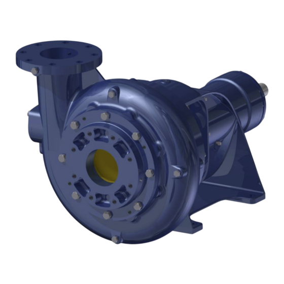
1.1 INTRODUCTION The Ruhrpumpen SHD type pump is a vertical or horizontal end-suction pump for solid handling. The vertically mounted pump has a structurally sufficient base to support the pump, motor and accessories, while the horizontally mounted pump is mounted on a common base plate with the driver. -
Page 8: Pump Case, Impeller, And Wear Rings
Vertical or Horizontal, Solid Handling Pump metallurgical, mechanical, and installation features for application in water, wastewater and river water. The following information is included in the nameplate of your pump unit: • Serial number • • Head • Capacity • Impeller diameter Please quote the pump serial number when ordering parts;... -
Page 9: Safety
Vertical or Horizontal, Solid Handling Pump 2. SAFETY This operation manual gives basic instructions that should be observed during installation, operation and maintenance of the pump. It is therefore imperative that this manual be read by the responsible personnel/operator prior to assembly and commissioning. It must always be kept available at the installation site. -
Page 10: Qualification And Training Of Operating Personnel
If the staff do not have the necessary knowledge, they must be trained and instructed. Training may be performed by a Ruhrpumpen representative on behalf of the plant operator. Moreover, the plant operator must ensure that the contents of the operating manual are fully understood by the personnel. -
Page 11: Safety Instructions Relevant For Maintenance, Inspection And Assembly Work
Modifications may be made to the machine only after consultation with a Ruhrpumpen representative. Using spare parts and accessories authorized by Ruhrpumpen is in the interest of safety. The use of parts not authorized by Ruhrpumpen are exempt from any liability, voiding the warranty. -
Page 12: Unauthorized Modes Of Operation
Vertical or Horizontal, Solid Handling Pump 2.8 UNAUTHORIZED MODES OF OPERATION The reliability of the machine is guaranteed if and only if it is used in the intended manner, in accordance with the statutes of this manual. The limit values specified in the data sheet must never be exceeded under any circumstance. -
Page 13: Transport & Storage
Handle all equipment carefully. Remove unit only by properly supporting the wooden shipping skid. After unloading, inspect the pump, check the shipment against the packing list, and report damages or shortages immediately to freight carrier and to the designated Ruhrpumpen representative. CAUTION Do not place lifting rig around bearing frame or under baseplate. -
Page 14: Transport
Vertical or Horizontal, Solid Handling Pump 3.3 TRANSPORT IMPORTANT The electric motor may be provided with a lifting eye, this lifting eye is intended only for the purpose of carrying out service activities to the electric motor only. NEVER lift a complete pump unit at the lifting eye of an electric motor. - Page 15 Incorrect transport of the pump. Damage to the shaft seal. Damage to the pump. • During transport, lock the pump shaft with a suitable device to prevent shaft movement. Figure 3.1 Correct position of the lifting ropes or chains – horizontal SHD pump. V1.081522...
-
Page 16: Storing
Vertical or Horizontal, Solid Handling Pump Figure 3.2 Correct position of the lifting ropes or chains – vertical SHD pump. 3.4 STORING CAUTION Damage during storage due to liquid ingress, humidity, dirt or vermin. Corrosion/contamination of the pump (set). •... - Page 17 Vertical or Horizontal, Solid Handling Pump If the pump is not installed immediately (within one month after shipping date), it should be safely stored prior to installation in a dry location free of dirt and grit. Furthermore, the pump unit (pump, driver, etc.) should not be subject to sudden temperature changes or vibrations.
- Page 18 When the pump is to be installed, remove all the protective coatings and desiccant and drain all oils. One month before installation, a Ruhrpumpen representative should be employed to conduct a final inspection. To properly store the motor (driver) for periods longer than one month, follow these steps: Store the motor in a clean, dry area, or cover it with a loose tarp (the tarp must be loose in order to prevent condensation).
-
Page 19: Conservation
Vertical or Horizontal, Solid Handling Pump If none are available, single phase or “trickle” heating may be utilized by energizing one phase of the motor’s windings with a low voltage, producing heat in the winding conductor. ATTENTION Request the required voltage and transformer capacity from the driver manufacturer. A third option is to use an auxiliary heat source and keep the windings warm by either convection or blowing warm dry air into the motor. -
Page 20: Disposal
Vertical or Horizontal, Solid Handling Pump WARNING Anticorrosive layers inside the pump housing must be removed with process neutral solvents before commencing pump operation. WARNING When removing the protective coating with a neutral solvent, follow the safety instructions of the solvent manufacturer carefully. ATTENTION The anticorrosive layer applied to the exposed parts does not need to be removed before putting the pump into operation. - Page 21 Vertical or Horizontal, Solid Handling Pump IMPORTANT This equipment may contain electrical/electronic equipment and must not be disposed with common waste because it is composed of different materials that can be recycled at the appropriate facilities. Inquire with your disposal company or by local ecological office to operate in compliance with the applicable laws.
-
Page 22: Inspection
Vertical or Horizontal, Solid Handling Pump DANGER Magnetic impact on personal health. Danger to life. • Never permit people to come in contact with Electro-Magnetic devices like motors, variable frequency drives, and magnetic drive assemblies who may have personal risks that can be impacted (e.g. pace-makers). •... - Page 23 Vertical or Horizontal, Solid Handling Pump NOTE All transmitting devices and radio equipment assemblies are sub-components of the pump (set) with their own installation, operating, and maintenance guidelines. All details can be found on nameplate(s) affixed to the device(s). Such devices have their own notified body approval, as indicated on the nameplate where applicable, and Conformity Risk Assessments.
-
Page 24: Installation
Vertical or Horizontal, Solid Handling Pump 4. INSTALLATION CAUTION Mishandling and improper installation of inflammable, toxic, or other substances that harmful. Danger to life and the environment. • Installation, foundation and maintenance of pumps handling inflammable liquids and other pollutive products may only be performed by authorized companies or their personnel. - Page 25 Vertical or Horizontal, Solid Handling Pump WARNING Unsecure installation on surfaces which are unsuitable for support the static and dynamic loads. Personal injury and damage to property. • Use concrete with compressive strength class C12/15 which meets the requirements of exposure class X0 to EN 206-1. •...
- Page 26 Bracket the pipe-work in close vicinity to the pump in which to isolate the pump from stress/strain. • Use expansion devices to accommodate thermal, local, and vibration movement of the piping. Correct and orderly installation/assembly is necessary for trouble-free operation of the unit. Ruhrpumpen does assume liability damage resulting...
-
Page 27: Concrete Foundation Preparation
API Recommended Practices 686. IMPORTANT The design of foundations is not the responsibility of Ruhrpumpen. It is therefore recommended that the customer consult a competent specialist skilled in the field of foundations, to insure proper design/installation of the foundation. - Page 28 Vertical or Horizontal, Solid Handling Pump Figure 4.1 Imaginary lines It is recommended to build the foundation approximately 3 inches (76 mm) larger overall than the pump baseplate to provide ample anchorage for the foundation bolts. 3.1. Since water can accidentally flow in the floor, a height for the surface of the foundation of 4 inches (100 mm) at least above floor level is recommended.
-
Page 29: Leveling Horizontal Baseplate
Vertical or Horizontal, Solid Handling Pump If your pump is a verticalized SHD pump, skip to SECTION 4.4 – LEVELING VERTICAL BASE to continue with the installation procedure. 4.2 LEVELING HORIZONTAL BASEPLATE NOTE The information included in this section is intended as a general guideline. For further information refer to the corresponding section in API Recommended Practices 686. -
Page 30: Grouting
Vertical or Horizontal, Solid Handling Pump DANGER Exercise proper caution when working under or around suspended objects. Using a precision level across baseplate pads, adjust wedges (shim packs) as necessary to ensure that baseplate is level in all directions (See the figure shown below); leveling within 0.002 in/ft (0.2 mm/m) is recommended. -
Page 31: Equipment/Material Required
Vertical or Horizontal, Solid Handling Pump IMPORTANT It is recommended that the customer consult a competent specialist skilled in the field of grouting to insure proper installation of all grouting. 4.3.1 Equipment/Material Required • Grout Mix: Non Shrink Type • Sufficient lumber for foundation template and grout trough. - Page 32 Vertical or Horizontal, Solid Handling Pump ATTENTION Apply three coats of paste wax to the inside surfaces of the forms in order to prevent adherence. Do not use oil or liquid wax. ATTENTION Prevent grout leakage, as leaks will not self-seal. Apply the grout, starting at one end of the form and advancing toward the other end.
-
Page 33: Leveling Vertical Base
Fill the holes with grout. Tighten the foundation bolts with an appropriate torque value. In case of doubt, please contact your Ruhrpumpen representative. Apply oil paint to exposed grout to protect from air and moisture. Use a lifting rig to position the pump and driver on their baseplate so that the mounting feet line up with their respective tapped holes. -
Page 34: Auxiliary Connections
Vertical or Horizontal, Solid Handling Pump 4.5 AUXILIARY CONNECTIONS WARNING Incorrect auxiliary liquid levels and wrong connections (e.g. seal barrier fluid, flushing liquids, pipe-connections, etc.). Risk of injury from leaking fluid. Risk of burns. Malfunction of the pump. • Consult the general arrangement drawing, the piping layout and pump markings (if any) for the quantity, dimensions and locations of auxiliary connections. -
Page 35: Direction Of Rotation Check
Vertical or Horizontal, Solid Handling Pump 4.7 DIRECTION OF ROTATION CHECK WARNING Trapped hands & fingers inside the pump casing. Risk of injuries, damage to the pump. • Always disconnect the pump set from the power supply and secure it against unintentional start-up before inserting your hands or other objects into the pump. - Page 36 Vertical or Horizontal, Solid Handling Pump CAUTION Excessive coupling misalignment. Damage to the pump. • Always check and align motor and coupling element(s) before starting the pump. • Follow the coupling alignment limits given in this installation operating and maintenance manual. •...
-
Page 37: Piping And Alignment
Vertical or Horizontal, Solid Handling Pump 5. PIPING AND ALIGNMENT DANGER Excessive loads acting on the pump nozzles/flanges. Danger to life from leakage of hot, toxic, corrosive or flammable fluids. • Always ensure that surrounding pipe-work is aligned to the pump without strain. -
Page 38: Piping The System
Vertical or Horizontal, Solid Handling Pump WARNING Do not start the piping and alignment procedures until grouting, preliminary alignment (as seen in the previous sections of this manual) and on site welding have been performed. ATTENTION In a new installation, great care should be taken to prevent dirt, scale, welding beads, and other items from entering the pump. - Page 39 Vertical or Horizontal, Solid Handling Pump IMPORTANT The design of piping and related systems is not the responsibility of Ruhrpumpen. It is, therefore, recommended that the customer consult a competent specialist skilled in the field of piping to insure proper design/installation of all the piping.
- Page 40 Vertical or Horizontal, Solid Handling Pump Figure 5.1. Correct mounting of a cone type strainer. Disconnect the piping from the pump if you heat one side of the pipe to align the pipe to the pump. Pump and pipe flanges must be parallel; they should mate together without effort, and with the bolt holes properly in line.
- Page 41 Vertical or Horizontal, Solid Handling Pump ATTENTION In horizontal suction lines, reducers should be eccentric (with the flat side of the reducer on top). ATTENTION No obstruction within at least five pipe diameters of the suction flange should be fitted. ATTENTION Do not install unsupported piping on the pump.
-
Page 42: Alignment
Vertical or Horizontal, Solid Handling Pump 5.2 ALIGNMENT NOTE The information included in this section is intended as a general guideline. For further information refer to the corresponding section in API Recommended Practices 686. IMPORTANT The tolerances for radial, axial and angular alignments must be of 0.05 mm (0.002 in) or lower. - Page 43 Vertical or Horizontal, Solid Handling Pump 2. Taking Alignment Readings It is suggested that the dial indicator be zeroed at the top. For convenience, you should mark your coupling at 0°, 90°, 180°, and 270° with a reference mark on the case so that you can be sure to turn the unit exactly 90°.
- Page 44 Vertical or Horizontal, Solid Handling Pump 3. Distance from the center of the motor front feet to the center of the motor back feet. In the example shown below, this is 5-1/4 inches (133.4 mm). Figure 5.2. Example for reverse indicator graphical analysis. The next step is to determine indicator sag.
- Page 45 Vertical or Horizontal, Solid Handling Pump Figure 5.3. Indicator sag. With the indicator bracket attached to the motor hub reading off the pump hub, rotate unit in 90° increments and take readings. Bottom reading is then corrected for indicator sag. Indicator sag in the example was determined to be 0.005 inch (0.127 mm).
- Page 46 Vertical or Horizontal, Solid Handling Pump Figure 5.4. Motor shaft extension relative to the pump shaft center line. Now with the indicator bracket attached to the pump hub reading off the motor hub, rotate unit again in 90° increments. NOTE If you can set up both indicators at once, both sets of readings can be taken at one time.
- Page 47 Vertical or Horizontal, Solid Handling Pump Figure 5.5. T.I.R. second reading. We have now located the motor shaft theoretical extension in two places: A. In the plane of the pump hub. B. In the plane of the motor hub. Drawing a straight line through these two points crossing the plane of the two motor feet. The shim adjustment can now be read directly off the graph.
- Page 48 Vertical or Horizontal, Solid Handling Pump C. REVERSE INDICATOR ALIGNMENT MORE THAN TWO UNITS GRAPHICAL ANALYSIS This method lends itself very well in solving alignment problems of three or more pieces of equipment in a line. To solve this problem, follow the steps already outlined for each coupling in the train. Plot the shaft to shaft relationship of each set of shafts.
- Page 49 Vertical or Horizontal, Solid Handling Pump Figure 5.8. Across the disc pack alignment graphical analysis example. The next step is to determine indicator sag. Set up your bracket arrangement on a pipe. Set the indicator at '0' on top. Roll set up until indicator is at the bottom of pipe. It will read negative. In this example, it was found to be -0.004 inch (-0.102 mm).
- Page 50 Vertical or Horizontal, Solid Handling Pump With the indicator bracket attached to the pump hub, reading out the center member a convenient distance, (in this example 8 inches [203.2 mm] was used) rotate the unit in 90° increments and take readings.
- Page 51 Vertical or Horizontal, Solid Handling Pump Bottom reading is corrected for indicator sag: ±0.008 inch (±0.203 mm) -0.004 inch (0.102 mm) = +0.012 inch (+0.309 mm). This is TIR so actual is +0.006 inch (+0.152 mm). (What we are trying to do here is determine the angle the center member makes with respect to the motor shaft.) The minus reading on the bottom indicates that the center member tips up as it extends away from the motor.
-
Page 52: Lubrication
Vertical or Horizontal, Solid Handling Pump 6. LUBRICATION 6.1 GREASE LUBRICATED BEARINGS Grease lubricated bearings are factory lubricated to prevent rusting for a short period of time only. Before starting the pump, the bearings must be properly greased. Check the bearings for the first hour or so after the pump has started up to ensure that they are functioning properly. -
Page 53: Regular Lubrication
Vertical or Horizontal, Solid Handling Pump 6.1.2 Regular Lubrication For grease lubricated bearings, connect the manual grease pump into the grease fitting and pump grease in until it begins to purge out from the bottom purge hole. ATTENTION Greased for life bearings do no need to have any grease added to them. 6.1.3 Complete Cleaning During a Major Overhaul If the bearings need cleaning or if an overhaul period offers the opportunity, the bearings and the housings should be cleaned out in the following manner:... -
Page 54: Mechanical Seals
Vertical or Horizontal, Solid Handling Pump 6.2.2 Mechanical Seals For proper lubrication of the mechanical seal, please refer to the provided seal plan drawing and the mechanical seal manufacturer’s manual. 6.3 MAINTENANCE It is recommended to inspect the bearings once a year as a regular maintenance procedure and replace them as needed. -
Page 55: Operation
Vertical or Horizontal, Solid Handling Pump 7. OPERATION IMPORTANT NEVER operate the pump in a system or under system conditions (flow, pressure, temperature, etc.) for which it has not been designed. NOTE The electric motor and drive assembly is a sub-component of the pump (set) with its own installation, operating, and maintenance guidelines. - Page 56 Vertical or Horizontal, Solid Handling Pump Pumps handling hot fluids (>500 °F, >260 °C) must be gradually preheated to operating temperature. The most common method used for warming a pump, or maintaining a standby pump in a warm condition, is the use of a warming line and orifice, thus circulating the hot pumpage through the idle pump.
-
Page 57: Startup
Vertical or Horizontal, Solid Handling Pump 7.2 STARTUP DANGER Abnormal noise, vibration, temperature or leakage. Damage to the pump. • Switch off the pump (set) immediately. • Eliminate the causes before returning the pump set to service. • Prepare an inspection & maintenance schedule with special emphasis on abnormal noise, vibration, and leakage. - Page 58 Vertical or Horizontal, Solid Handling Pump ATTENTION Immediately observe the pressure gauges. If the discharge pressure is not quickly attained, stop the driver, re-prime and attempt to restart. Adjust the discharge valve until rated flow is obtained. ATTENTION A sudden increase of running noise is always a sign of possible trouble. WARNING Every time before the pump is started up the safety devices must be mounted and fastened.
- Page 59 Vertical or Horizontal, Solid Handling Pump Figure 7.1. Seal setting devices. The startup procedure is as follows: Before starting the pump, check the security of all bolting, piping, and wiring. Check all gauges, valves and instruments for proper working order. Check that all the equipment is properly lubricated and rotates in the correct direction.
-
Page 60: Startup Frequency
Vertical or Horizontal, Solid Handling Pump Once priming has been accomplished and correct shaft rotation has been established, the pump is ready for continued operation. Securely couple the driver and the pump, and ensure the discharge valve is opened to approximately ¼... - Page 61 To monitor flow, pressure, temperature, and lubrication, regular visual inspection and monitoring is advisable and/or necessary during operation. Ruhrpumpen recommends checking the pump constantly at regular intervals in order to detect problems early, in case they arise. The operational check routine must include at least the following points: DANGER Beware of freely rotating parts, when the pump is in operation there is a high risk of injury.
-
Page 62: Doweling (Optional)
Vertical or Horizontal, Solid Handling Pump b. If leakage is excessive, switch the pump off as quickly as possible, isolate the pump by closing the discharge and suction valves or by using some other approved method designated as safe for your system, and check the rotating seal ring and the stationary seal ring. -
Page 63: Shutdown
Vertical or Horizontal, Solid Handling Pump ATTENTION If the rotor is jerky or suddenly stops, there is danger that the rotor has become blocked. The pump must be opened and all running clearances checked. Close the suction valve when the pump shaft stops rotating as the pump must be isolated before examination and made safe. -
Page 64: Short-Term Shutdown
Vertical or Horizontal, Solid Handling Pump CAUTION Reverse rotation of the pump caused by fluid backflow is not permitted. Motor or winding damage. Mechanical seal damage. • Close the isolation valve(s) when the pump is not running. • Install non-return device in the discharge line. Risk of freezing due to exposure to low temperatures during prolonged periods of pump shutdown. -
Page 65: Ambient Temperature
Vertical or Horizontal, Solid Handling Pump 7.7 AMBIENT TEMPERATURE CAUTION Operation outside the permissible ambient temperature. Damage to the pump and motor. • Observe the specified pump (set) and auxiliary device limits for permissible ambient temperatures. • Always use motors that are suitable for the atmospheric humidity conditions. 7.8 FLUIDS BEING HANDLED CAUTION Excessively high density fluids being handled. -
Page 66: Maintenance
Vertical or Horizontal, Solid Handling Pump 8. MAINTENANCE To perform the maintenance of the SHD pump, no special (custom made) tools are needed. CAUTION Mishandling and improper installation of inflammable, toxic, or other substances that are harmful. Danger to life and the environment •... -
Page 67: Shd Pump Disassembly
IMPORTANT For any component/accessory that has not been manufactured by Ruhrpumpen and is part of the pump´s equipment, a complete reading of said component/accessory manufacturer´s manual must be carried out for further information on proper maintenance procedures and relevant safety warnings. -
Page 68: Horizontal Shd Pump - Packing Strips Option Disassembly
Remove the impeller gasket from the shaft sleeve. Remove the corresponding gasket from the case cover. To disassemble the horizontal SHD pump – packing strips option, follow the steps detailed below. For the mechanical seal option disassembly procedure, please refer to Section 8.1.2 Horizontal SHD Pump –... -
Page 69: Horizontal Shd Pump - Mechanical Seal Option Disassembly
Remove the shaft sleeve from the shaft. 8.1.2 Horizontal SHD Pump – Mechanical Seal Option Disassembly Follow steps 1 thru 22 from Section 8.1.1 Horizontal SHD Pump – Packing Strips Option Disassembly and then continue with the following steps: a. Untighten and remove the hex bolts that secure the mechanical seal gland to the case cover. -
Page 70: Vertical Shd Pump - Packing Strips Option Disassembly
Vertical or Horizontal, Solid Handling Pump 8.1.3 Vertical SHD Pump – Packing Strips Option Disassembly Stop the pump. See SECTION 7.5 - STOPPING. Drain all possible fluids from the pump case and power frames. Disconnect any auxiliary piping and wiring that could interfere with disassembly (for example, cooling coil or cooling jacket piping). - Page 71 Remove the non-coupling side key from the non-coupling side shaft´s keyway. Remove the shaft sleeve gasket from the shaft sleeve. To disassemble the vertical SHD pump – packing strips option, follow the steps detailed below. For the mechanical seal option disassembly procedure, please refer to Section 8.1.4 Vertical SHD Pump –...
-
Page 72: Vertical Shd Pump - Mechanical Seal Option Disassembly
Remove the retainer ring from the shaft. 8.1.4 Vertical SHD Pump – Mechanical Seal Option Disassembly Follow steps 1 thru 37 from Section 8.1.3 Vertical SHD Pump – Packing Strips Option Disassembly and then continue with the following steps: a. Untighten and remove the hex bolts to secure the mechanical seal gland to the case cover. -
Page 73: Shd Pump Reassembly
Vertical or Horizontal, Solid Handling Pump 8.3 SHD PUMP REASSEMBLY 8.3.1 Horizontal SHD Pump – Packing Strips Option Reassembly Insert the shaft sleeve over the shaft from the non-coupling side. Figure 8.3.1 Inserting the shaft sleeve over the shaft from the non-coupling side. - Page 74 Vertical or Horizontal, Solid Handling Pump ATTENTION If there is no way of properly heating the bearing for installation, a bearing installation kit approved by the bearing manufacturer can be used to perform a bearing installation at room temperature. Figure 8.3.3 Example of a bearing installation kit approved by the bearing manufacturer. Insert the coupling side (axial) bearing housing over the shaft from the coupling side.
- Page 75 Vertical or Horizontal, Solid Handling Pump Insert the coupling side (axial) bearing over the shaft from the coupling side. Figure 8.3.5 Inserting the coupling side (axial) bearing over the shaft from the coupling side. ATTENTION The bearing must be heated to 100 °C / 212 °F. The bearing should be passed 3 times over the heater for demagnetization.
- Page 76 Vertical or Horizontal, Solid Handling Pump Insert the coupling side (axial) bearing lockwasher over the shaft from the coupling side. Figure 8.3.7 Inserting the coupling side (axial) bearing lockwasher over the shaft from the coupling side. ATTENTION Make sure that the latch on the inner diameter of the coupling side (axial) bearing lockwasher matches the groove on the shaft.
- Page 77 Vertical or Horizontal, Solid Handling Pump ATTENTION In search of a match between a tab of the non-coupling side (axial) bearing lockwasher and a slot of the non-coupling side (axial) bearing locknut, the locknut should always move forward, never backwards. Insert the rotor assembly inside the bearing bracket from the non-coupling side.
- Page 78 Vertical or Horizontal, Solid Handling Pump Place and tighten the hex bolts to secure the coupling side (axial) bearing cover and the coupling side (axial) bearing housing to the bearing bracket. Figure 8.3.11 Placing and tightening the hex bolts to secure the coupling side (axial) bearing cover and the coupling side (axial) bearing housing to the bearing bracket.
- Page 79 If your pump uses a mechanical seal as a sealing option, please follow the instructions on Section 8.3.2 Horizontal SHD Pump – Mechanical Seal Option Reassembly to install the mechanical seal. Otherwise, continue with the following steps. To install the packing strip sets, the lantern ring and the packing gland, follow these steps: a.
- Page 80 Vertical or Horizontal, Solid Handling Pump b. Insert the first set of packing strips over the shaft from the non-coupling side. Figure 8.3.14b Inserting the first set of packing strips over the shaft from the non-coupling side. c. Insert the lantern ring over the shaft from the non-coupling side until it reaches the first set of packing strips.
- Page 81 Vertical or Horizontal, Solid Handling Pump d. Insert the second set of packing strips over the shaft from the non-coupling side until it reaches the lantern ring. Figure 8.3.14d Inserting the second set of packing strips over the shaft from the non-coupling side until it reaches the lantern ring.
- Page 82 Vertical or Horizontal, Solid Handling Pump e. Insert the case cover over the shaft from the non-coupling side until it reaches the bearing bracket. Figure 8.3.14e Inserting the case cover over the shaft from the non-coupling side until it reaches the bearing bracket.
- Page 83 Vertical or Horizontal, Solid Handling Pump f. Place and tighten the hex bolts that secure the case cover to the bearing bracket. Figure 8.3.14f Placing and tightening the hex bolts that secure the case cover to the bearing bracket. V1.081522...
- Page 84 Vertical or Horizontal, Solid Handling Pump g. Push the packing gland towards the case cover. This will also insert the packing strip sets and the lantern ring inside the case cover´s stuffing box. Figure 8.3.14g Pushing the packing gland towards the case cover. h.
- Page 85 Vertical or Horizontal, Solid Handling Pump Place the corresponding gasket on the case cover. Figure 8.3.15 Placing the corresponding gasket on the case cover. Place the impeller gasket on the shaft sleeve Figure 8.3.16 Placing the impeller gasket on the shaft sleeve. V1.081522...
- Page 86 Vertical or Horizontal, Solid Handling Pump Place the square key on the on the shaft´s non-coupling side keyway. Figure 8.3.17 Placing the square key on the shaft´s non-coupling side keyway. Insert the impeller over the shaft from the non-coupling side. Figure 8.3.18 Inserting the impeller over the shaft from the non-coupling side.
- Page 87 Vertical or Horizontal, Solid Handling Pump Insert the impeller washer over the shaft from the non-coupling side until it reaches the impeller. Figure 8.3.19 Inserting the impeller washer over the shaft from the non-coupling side until it reaches the impeller. Place and tighten the hex bolt to secure the impeller washer and the impeller to the shaft.
- Page 88 Vertical or Horizontal, Solid Handling Pump Place the case on the case cover. Figure 8.3.21 Placing the case on the case cover. V1.081522...
- Page 89 Vertical or Horizontal, Solid Handling Pump Place and tighten the hex socket head screws to secure the case to the case cover and the bearing bracket. Figure 8.3.22 Placing and tightening the hex socket head screws to secure the case to the case cover and the bearing bracket.
- Page 90 Vertical or Horizontal, Solid Handling Pump Place the corresponding gasket on the case. Figure 8.3.23 Placing the corresponding gasket on the case. Place the suction case on the case. Figure 8.3.24 Placing the suction case on the case. V1.081522...
- Page 91 Vertical or Horizontal, Solid Handling Pump Place and tighten the hex bolts to secure the suction case to the case. Figure 8.3.25 Placing and tightening the hex bolts to secure the suction case to the case. Place the lateral case plug on the case. Figure 8.3.26 Placing the lateral case plug on the case.
- Page 92 Vertical or Horizontal, Solid Handling Pump Place and tighten the hex bolts to secure the lateral case plug to the case. Figure 8.3.27 Placing and tightening the hex bolts to secure the lateral case plug to the case. Place and tighten the threaded hex plugs on the back of the case. Figure 8.3.28 Placing and tightening the threaded hex plugs on the back of the case.
- Page 93 Vertical or Horizontal, Solid Handling Pump Place and tighten the threaded hex plugs on the front of the case. Figure 8.3.29 Placing and tightening the threaded hex plugs on the front of the case. V1.081522...
- Page 94 Vertical or Horizontal, Solid Handling Pump Place and tighten the threaded hex plugs on the bearing bracket. Figure 8.3.30 Placing and tightening the threaded hex plugs on the bearing bracket. V1.081522...
- Page 95 Vertical or Horizontal, Solid Handling Pump Place the square key on the shaft´s coupling side keyway. Figure 8.3.31 Placing the square key on the shaft´s coupling side keyway. Horizontal SHD pump assembly has been completed. Figure 8.3.32 Complete horizontal SHD pump assembly. V1.081522...
-
Page 96: Horizontal Shd Pump - Mechanical Seal Option Reassembly
Vertical or Horizontal, Solid Handling Pump 8.3.2 Horizontal SHD pump – Mechanical Seal Option Reassembly To assemble the horizontal SHD pump mechanical seal option follow steps 1 thru 11 from Section 8.3.1 Horizontal SHD Pump – Packing Strips Option Reassembly and then continue with the following steps: a. - Page 97 Vertical or Horizontal, Solid Handling Pump c. Insert the case cover over the shaft from the non-coupling side. Figure 8.3.14MSc Inserting the case cover over the shaft from the non-coupling side. V1.081522...
- Page 98 Vertical or Horizontal, Solid Handling Pump d. Place and tighten the hex bolts to secure the case cover to the bearing bracket. Figure 8.3.14MSd Placing and tightening the hex bolts to secure the case cover to the bearing bracket. V1.081522...
- Page 99 Figure 8.3.14MSf Placing and tightening the hex bolts to secure the mechanical seal gland to the case cover. Proceed with Section 8.3.1 Horizontal SHD Pump – Packing Strips Option Reassembly step 13 to continue with the rest of the horizontal pump´s assembly.
-
Page 100: Vertical Shd Pump - Packing Strips Option Reassembly
Vertical or Horizontal, Solid Handling Pump 8.3.3 Vertical SHD Pump – Packing Strips Option Reassembly Insert the retainer ring over the shaft from the non-coupling side. Figure 8.3.33 Inserting the retainer ring over the shaft from the non-coupling side. Insert the non-coupling side (radial) bearing over the shaft from the non-coupling side. - Page 101 Vertical or Horizontal, Solid Handling Pump ATTENTION If there is no way of properly heating the bearing for installation, a bearing installation kit approved by the bearing manufacturer can be used to perform a bearing installation at room temperature. Figure 8.3.35 Example of a bearing installation kit approved by the bearing manufacturer. Insert the coupling side (axial) bearing housing over the shaft from the coupling side.
- Page 102 Vertical or Horizontal, Solid Handling Pump Insert the coupling side (axial) bearing over the shaft from the coupling side. Figure 8.3.37 Inserting the coupling side (axial) bearing over the shaft from the oupling side. ATTENTION The bearing must be heated to 100 °C / 212 °F. The bearing should be passed 3 times over the heater for demagnetization.
- Page 103 Vertical or Horizontal, Solid Handling Pump Insert the rotor assembly inside the bearing bracket from the coupling side. Figure 8.3.39 Inserting the rotor assembly inside the bearing bracket from the coupling side. Insert the coupling side (axial) bearing cover over the shaft from the coupling side. Figure 8.3.40 Inserting the coupling side (axial) bearing cover over the shaft from the coupling side.
- Page 104 Vertical or Horizontal, Solid Handling Pump Place and tighten the hex bolts that secure the coupling side (axial) bearing cover to the bearing bracket. Figure 8.3.41 Placing and tightening the hex bolts that secure the coupling side (axial) bearing cover to the bearing bracket.
- Page 105 Figure 8.3.44 Inserting the shaft sleeve over the shaft from the non-coupling side- If your pump uses a mechanical seal as a sealing option, please follow the instructions on Section 8.3.4 – Vertical SHD Pump – Mechanical Seal Option Reassembly to install the mechanical seal. Otherwise, continue with the following steps.
- Page 106 Vertical or Horizontal, Solid Handling Pump To install the packing strip sets, the lantern ring and the packing gland, follow these steps: a. Insert the packing gland over the shaft from the non-coupling side. Figure 8.3.45a Inserting the packing gland over the shaft from the non-coupling side. b.
- Page 107 Vertical or Horizontal, Solid Handling Pump c. Insert the lantern ring over the shaft from the non-coupling side. Figure 8.3.45c Inserting the lantern ring over the shaft from the non-coupling side. d. Insert the second set of packing strips over the shaft from the non-coupling side. Figure 8.3.45d Inserting the second set of packing strips over the shaft from the non-coupling side.
- Page 108 Vertical or Horizontal, Solid Handling Pump e. Insert the case cover over the shaft from the non-coupling side. Figure 8.3.45e Inserting the case cover over the shaft from the non-coupling side. f. Place and tighten the hex bolts that secure the case cover to the bearing bracket. Figure 8.3.45f Placing and tightening the hex bolts that secure the case cover to the bearing bracket.
- Page 109 Vertical or Horizontal, Solid Handling Pump ATTENTION The joining faces of each strip must not be aligned, to ensure a proper assembly and function. ATTENTION When performing any kind of maintenance that requires the pump to be opened, the packing strips must be replaced. ATTENTION The quantity of packing strips in the first and second sets of packing strips may vary in order to position the lantern ring on the seal flush line hole.
- Page 110 Vertical or Horizontal, Solid Handling Pump Place the shaft sleeve gasket on the shaft sleeve. Figure 8.3.46 Placing the shaft sleeve gasket on the shaft sleeve. Place the non-coupling side key on the non-coupling side shaft´s keyway. Figure 8.3.47 Placing the non-coupling side key in the non-coupling side shaft´s keyway. V1.081522...
- Page 111 Vertical or Horizontal, Solid Handling Pump Insert the impeller over the shaft from the non-coupling side. Figure 8.3.48 Inserting the impeller over the shaft from the non-coupling side. Place the impeller washer O-ring in the impeller washer. Figure 8.3.49 Placing the impeller washer O-ring in the impeller washer. V1.081522...
- Page 112 Vertical or Horizontal, Solid Handling Pump Place the impeller washer on the shaft. Figure 8.3.50 Placing the impeller washer on the shaft. Place and tighten the impeller screw to fix the impeller and the impeller washer to the shaft. Figure 8.3.51 Placing and tightening the impeller screw to fix the impeller and the impeller washer to the shaft. V1.081522...
- Page 113 Vertical or Horizontal, Solid Handling Pump Place the corresponding gasket on the case cover. Figure 8.3.52 Placing the corresponding gasket on the case cover. Insert the case over the impeller until it reaches the case cover. Figure 8.3.53 Inserting the case over the impeller until it reaches the case cover. V1.081522...
- Page 114 Vertical or Horizontal, Solid Handling Pump Place and tighten the socket head screws to secure the case to the case cover and the bearing bracket. Figure 8.3.54 Placing and tightening the socket head screws to secure the case to the case cover and the bearing bracket.
- Page 115 Vertical or Horizontal, Solid Handling Pump Place and tighten the hex bolts that fix the lateral case plug to the case. Figure 8.3.56 Placing and tightening the hex bolts that fix the lateral case plug to the case. Place the corresponding gasket on the front of the case. Figure 8.3.57 Placing the corresponding gasket on the front of the case.
- Page 116 Vertical or Horizontal, Solid Handling Pump Place the suction case on the case. Figure 8.3.58 Placing the suction case on the case. Place and tighten the hex bolts that fix the suction case to the case. Figure 8.3.59 Placing and tightening the hex bolts that fix the suction case to the case. V1.081522...
- Page 117 Vertical or Horizontal, Solid Handling Pump Place the corresponding gasket on the suction case. Figure 8.3.60 Placing the corresponding gasket on the suction case. Place the suction elbow on the suction case. Figure 8.3.61 Placing the suction elbow on the suction case. V1.081522...
- Page 118 Vertical or Horizontal, Solid Handling Pump Place and tighten the hex bolts to fix the suction elbow to the suction case. Figure 8.3.62 Placing and tightening the hex bolts that fix the suction elbow to the suction case. V1.081522...
- Page 119 Vertical or Horizontal, Solid Handling Pump Place the suction elbow O-ring on the handhole cover connection. Figure 8.3.63 Placing the suction elbow O-ring on the handhole cover connection. Place the handhole cover on the suction elbow. Figure 8.3.64 Placing the handhole cover on the suction elbow. V1.081522...
- Page 120 Vertical or Horizontal, Solid Handling Pump Place and tighten the hex bolts that fix the handhole cover to the suction elbow. Figure 8.3.65 Placing and tightening the hex bolts that fix the handhole cover to the suction elbow. Carefully lift the pump assembly with a crane and place it on the vertical adapter Figure 8.3.66 Placing the pump assembly on the vertical adapter.
- Page 121 Vertical or Horizontal, Solid Handling Pump Place the corresponding washers on the vertical s. Figure 8.3.67 Placing the corresponding washers on the vertical adapter. Place and tighten the hex bolts that secure the vertical adapter to the suction case. Figure 8.3.68 Placing and tightening the hex bolts that secure the vertical adapter to the suction case. V1.081522...
- Page 122 Vertical or Horizontal, Solid Handling Pump Place the flush line connectors on the case and the packing gland. Figure 8.3.69 Placing the flush line connectors on the case and the packing gland. Place the flush line tubing on the flush line connectors place on the previous step. Figure 8.3.70 Placing the flush line tubing on the flush line connectors.
- Page 123 Vertical or Horizontal, Solid Handling Pump Place the case cover plugs on the case cover. Figure 8.3.71 Placing the case cover plugs on the case cover. Place the packing gland plug on the packing gland. Figure 8.3.72 Placing the packing gland plug on the packing gland. V1.081522...
- Page 124 Vertical or Horizontal, Solid Handling Pump Place the case back plugs on the case. Figure 8.3.73 Placing the case back plugs on the case. Place the case front plugs on the case. Figure 8.3.74 Placing the case front plugs on the case. V1.081522...
- Page 125 Vertical or Horizontal, Solid Handling Pump Place the case discharge plug on the case. Figure 8.3.75 Placing the case discharge plug on the case. Place the coupling side key on the shaft´s coupling side keyway. Figure 8.3.76 Placing the coupling side key on the shaft´s coupling side keyway. V1.081522...
- Page 126 Vertical or Horizontal, Solid Handling Pump Place the suction case plug on the suction case. Figure 8.3.77 Placing the suction case plug on the suction case. Vertical SHD pump assembly is complete. Figure 8.3.78 Complete vertical SHD pump assembly. V1.081522...
-
Page 127: Vertical Shd Pump - Mechanical Seal Option Reassembly
8.3.4 Vertical SHD Pump – Mechanical Seal Option Reassembly To assemble the mechanical seal on a vertical SHD pump, follow steps 1 thru 10 of Section 8.3.3 Vertical SHD Pump – Packing Strips Option Reassembly and then continue with these steps: a. - Page 128 Vertical or Horizontal, Solid Handling Pump c. Insert the mechanical seal over the shaft inside the mechanical seal gland. Figure 8.3.45MSc Inserting the mechanical seal over the shaft inside the mechanical seal gland. d. Insert the case cover over the shaft from the non-coupling side. Figure 8.3.45MSd Inserting the case cover over the shaft from the non-coupling side.
- Page 129 Vertical or Horizontal, Solid Handling Pump e. Place and tighten the hex bolts to secure the case cover to the bearing bracket. Figure 8.3.45MSe Placing and tightening the hex bolts to secure the case cover to the bearing bracket. f. Push the mechanical seal gland towards the case cover. This will insert the mechanical seal inside the case cover.
- Page 130 Figure 8.3.45MSg Placing and tightening the hex bolts to secure the mechanical seal gland to the case cover. Proceed with Section 8.3.3 Vertical SHD Pump – Packing Strips Option Reassembly step 12 to continue with the rest of the vertical pump´s assembly.
-
Page 131: Spare Parts
ATTENTION The quantities of spare parts given on the list below are the minimum standard quantities to be had. However, these quantities may vary depending on individual working conditions. For more information, please contact a Ruhrpumpen representative. DESCRIPTION STARTUP 1 - 3 YEARS... - Page 132 Vertical or Horizontal, Solid Handling Pump Material storage of spare parts • Store the spare parts in their original packaging. • Store in a dry place, preferably at a constant temperature. • Check the spare parts and the state of the packaging every 6 months for signs of corrosion. •...
-
Page 133: Parts Information
Vertical or Horizontal, Solid Handling Pump 10. PARTS INFORMATION Figure 10.1 Sectional Drawing Horizontal SHD Pump – Packing Strips Option. V1.081522... - Page 134 Vertical or Horizontal, Solid Handling Pump Parts List Horizontal SHD Pump – Packing Strips Option. ITEM DESCRIPTION ITEM DESCRIPTION CASE 400.1 GASKET SUCTION CASE 400.2 GASKET CASE COVER 400.3 GASKET PACKING STRIP LANTERN RING PUMP SHAFT PACKING GLAND NON-COUPLING SIDE (RADIAL)
- Page 135 Vertical or Horizontal, Solid Handling Pump Figure 10.2 Sectional Drawing Horizontal SHD Pump – Mechanical Seal Option. V1.081522...
- Page 136 Vertical or Horizontal, Solid Handling Pump Parts List Horizontal SHD Pump – Mechanical Seal Option. ITEM DESCRIPTION ITEM DESCRIPTION CASE 400.2 GASKET SUCTION CASE 400.3 GASKET CASE COVER MECHANICAL SEAL PUMP SHAFT MECHANICAL SEAL GLAND NON-COUPLING SIDE (RADIAL) IMPELLER DEFLECTOR...
- Page 137 Vertical or Horizontal, Solid Handling Pump Figure 10.3 Sectional Drawing Vertical SHD Pump – Packing Strips Option. V1.081522...
-
Page 138: Item Description
Vertical or Horizontal, Solid Handling Pump Parts List Vertical SHD Pump – Packing Strips Option. ITEM DESCRIPTION ITEM DESCRIPTION COUPLING SIDE (AXIAL) CASE BEARING COVER SUCTION CASE LANTERN RING SUCTION ELBOW PACKING GLAND NON-COUPLING SIDE VERTICAL ADAPTER (RADIAL) DEFLECTOR CASE COVER... - Page 139 Vertical or Horizontal, Solid Handling Pump Figure 10.4 Sectional Drawing Vertical SHD Pump – Mechanical Seal Option. V1.081522...
- Page 140 Vertical or Horizontal, Solid Handling Pump Parts List Vertical SHD Pump – Mechanical Seal Option. ITEM DESCRIPTION ITEM DESCRIPTION COUPLING SIDE (AXIAL) CASE BEARING COVER SUCTION CASE MECHANICAL SEAL SUCTION ELBOW MECHANICAL SEAL GLAND NON-COUPLING SIDE VERTICAL ADAPTER (RADIAL) DEFLECTOR...
-
Page 141: Troubleshooting Chart
SHAFT SEAL properly aligned. a. Inner pump parts a. Change worn parts. are worn. b. Consult a Ruhrpumpen dealer. b. Density or viscosity c. Apply correct voltage to the motor. of pumped fluid is d. Check the cables, connections and fuses. - Page 142 Install vent valve or lay piping elsewhere. h. Feed pipe or j. Change worn parts. impeller plugged. k. Consult a Ruhrpumpen dealer. CAPACITY OR i. Formation of air l. Apply correct voltage to the motor. DISCHARGE pockets in the m.
-
Page 143: Extended Warranty
Fifteen days prior to the initial operation, a Ruhrpumpen Service Engineer must be hired by the customer to thoroughly inspect the pump to confirm that the pump is in a “as shipped” condition. -
Page 144: Pump Operation Log
Vertical or Horizontal, Solid Handling Pump • The customer must send the equipment to an authorized Ruhrpumpen service center for maintenance every 48 months to replace all worn parts and so that a general inspection on the pump can be performed. Failure to comply with this will void the warranty. - Page 145 Vertical or Horizontal, Solid Handling Pump CONDITION RECORDED ITEM YES NO VALUES equipped drain is able to empty the drip pan. If no mechanical seals are equipped, make sure that all environmental controls are correctly connected and fully functional. Check that all monitoring devices (low pressure switches, flow meters, RTDs, temperature sensors, etc.) are connected and operational.
- Page 146 +70 years creating the pumping technology that moves our world Ruhrpumpen is an innovative and efficient pump technology company that offers highly-engineered and standard pumping solutions for the oil & gas, power generation, industrial, water and chemical markets. We offer a broad range of centrifugal and reciprocating pumps that meet and exceed the requirements of the most demanding quality specifications and industry standards such as API, ANSI, UL, FM, ISO and Hydraulic Institute.
Need help?
Do you have a question about the SHD and is the answer not in the manual?
Questions and answers