
Related Manuals for Zenitel TMIS-1


Summary of Contents for Zenitel TMIS-1
- Page 1 TECHNICAL MANUAL Turbine IP Intercoms TCIS / TCIV+ / TEIV+/TFIE / TFIX / TMIS / ECPIR-3P A100K11194 zenitel.com Turbine Stations Technical Manual...
-
Page 2: Table Of Contents
3. 1 1.2017 TFIE-6, VS-IS 4.7 3 Starting Up the Station June 2020 IC-EDGE 4 ICX-AlphaCom Configuration 3. 1 22.2.2021 TCIV+, Zenitel branding Logging into the Station April 2022 New Template, TFIX-X-V2, TMIS-4, TMIV-1 Main Settings 4. 1 Sept 23 TEIV+... - Page 3 5 IC-EDGE Configuration 6 SIP Configuration Logging into the Station Logging into the Station Main Settings Main Settings Connect other Intercom Stations Account/Call Settings Configure Edge Controller Directory Audio Settings Verify System Setup Direct Settings Configure Call and Audio Settings Relay/Output Settings Modify IC-EDGE Device Profiles Time Settings...
-
Page 4: Turbine Compact Intercoms
TA-34 Turbine Extended Flushmount Backbox- 1008140340 Turbine Extended IP Video with RFID card TEIV-4+ 1008318240 reader mount TMIS-1/TMIV-1+ Turbine Mini TMIS-2 Turbine Mini TMIS-4 Turbine Mini Thermoplastic Frontplate with Single Stainless Steel Frontplate with Single Thermoplastic Frontplate with Two Call... -
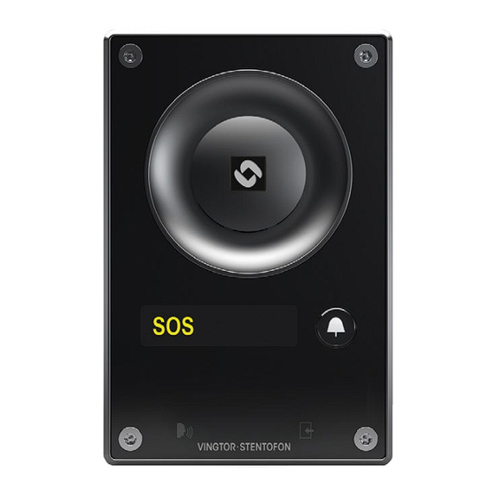
Page 5: Turbine Compact Station Keys & Functions
1.1.1 Turbine Compact Station Keys & Functions 1.2 Connectors on Turbine Compact Intercom This Turbine Compact Board is used by the following stations: TCIS-1, TCIS-2, TCIS-3, TCIS-4, TCIS-5, TCIS-6, TKIS-2, TMIS-1, TMIS-4. Note! The TCIA-2 has a different set of connectors. Speaker Speaker See Appendix A: Compact Board Connectors for further information. -
Page 6: Power Supply
This Turbine Compact Board is used by the following video stations: 1.2.3 Input/Output Connections TMIV-1+, T CIV-2+, TCIV-3+, TCIV-5+, TCIV-6+, TEIV-1+ and TEIV-4+ There are 6 I/O connection options for the Turbine Compact Station. These connections can be used to interface with external I/O devices. -
Page 7: Turbine Extended Station Keys & Functions
2.1.1 Turbine Extended Station Keys & Functions 2.1.2 ECPIR-3P Indoor Intercom - Keys & Functions ECPIR-3P Turbine TFIE-1/TFIX-1-V2 Turbine TFIE-2/TFIX-2-V2 Indoor Intercom with 3 Programmable Keys 2.1.3 TKIE-2 Turbine Extended Kit Power Fault Power Fault Call Call TKIE-2 Turbine TFIE-6 Turbine TFIX-3-V2 Turbine Extended IP Kit Speaker... -
Page 8: Connectors On Turbine Industrial
2.2 Connectors on Turbine Industrial 2.2.3 Input/Output Connections The Turbine Extended board is used in the following stations: TFIE-1, TFIE-2, TFIE-6, ECPIR-3P, TKIE-1. There are 6 I/O connection options for the Turbine Industrial Station. These connections are used as digital input (eg. form a closing contact), digital output (5 V), or LED driving (20mA max.) for connecting sensors, indicators or integration See Appendix B: Extended Board Connectors for further information. -
Page 9: Ak5850Hs Headset Ta-22B Plugbox
2.2.4.2 AK5850HS Headset TA-22b Plugbox 2.2.4.3 EMMAI-2H Handheld Compact Microphone AK5850HS TA-22b EMMAI-2H Plug the IDC connectors on the Compact Microphone cable into the J8 terminal block according to the pin configuration Plugbox & Cable (10 m.) for Headset Handheld Compact Industrial Headset with boom microphone and below. -
Page 10: Connect Accessories
2.3.1 Connect Accessories 2.3.1.2 AK5850HS Headset TAX-2b Plugbox Accessories are connected to the top 16-screw connection terminal block in the Turbine Ex enclosure. AK5850HS TAX-2b Plugbox & Cable (10 m.) for Headset Headset with boom microphone and with PTT curled cord 4 5 6 7 8 9 10 11 12 13 14 3 | Signal GND 4 | Audio Accessory Speaker +... -
Page 11: Emmax-1H Handheld Compact Microphone
2.3.1.3 EMMAX-1H Handheld Compact Microphone 2.5 Connect External Signaling Device EMMAX-1H A signal beacon can be connected to the Relay terminals located on the bottom connection terminal block in the Connect the wire ferrules on the Compact Microphone cable Turbine Ex enclosure. Handheld Compact Industrial Microphone to the terminal block according to the pin configuration below. -
Page 12: Connect Ebmdr-8 To Ecpir-3P
3. Connect the black connector on the cable to the corresponding black connector on the EBMDR-8. be carried out on the actual station. For more information on ICX-AlphaCom configuration see wiki.zenitel.com/wiki/Turbine_Configuration_-_AlphaCom_ mode The following sections describe configuration procedures using the web interface of the station. -
Page 13: Audio Settings
• TFIX-3-V2 • Handset w/ Offhook • Labels (TCIS-4, TCIS-5) • TFIE-6 • Handset w/ Offhook • Scrolling Station (TCIS-6) • ECPIR-3P (Normally Closed) • Mini (TMIS-1, TMIS-2, • Handheld TMIS-4) Microphone • Headset • Headset w/ Auto detect Registration Settings: ICX-AlphaCom IP-Address •... -
Page 14: I/O Settings
• AVC Advanced Note! This feature must be used with caution as incorrect settings may severely degrade the performance of the echo-cancelling algorithm. • AVC Lower Threshold: Threshold level for AVC starts working. Valid range: [-92..0] dBm0 • AVC Upper Threshold: Threshold level for AVC stops working. Valid range: [-92..0] dBm0 •... -
Page 15: Address Book
4.5 Address Book • Download or View Address Book • DOWNLOAD or VIEW the address book Note! Only the Turbine Compact station configured as a Scrolling Station (TCIS-6, TCIV-6+, TFIE-6) under • Upload Address Book, A CSV file consisting of directory Main Settings will have this menu option. -
Page 16: Sound Detection
For more information on IC-EDGE configuration, see wiki.zenitel.com/wiki/Category:IC-EDGE_Configuration. One of the stations must be set as the Edge Controller. The Edge Controller acts as a server for the other intercom stations in the system. -
Page 17: Main Settings
• Labels (TCIS-4, TCIS-5) • TFIE-6 • Handset w/ Offhook • Scrolling Station (TCIS-6) • ECPIR-3P (Normally Closed) • Mini (TMIS-1, TMIS-2, • Handheld Microphone TMIS-4) • Headset • Headset w/ Auto You can now set Numbers, Names, IP addresses, Profiles, etc. for all the stations in the network. In our example, the... -
Page 18: Verify System Setup
5.5 Verify System Setup 5.7 Modify IC-EDGE Device Profiles To verify that the devices are successfully registered to the Edge Controller: The Station Profile defines a set of service features and parameters that are available for a group of devices. •... -
Page 19: Group Call
Chime. Enables the playing of a ding-dong chime when a device receives a Group Call. Group Call audio can be sent and received by all Zenitel IP stations and can be sent from most modern SIP IP phones. Group Call audio can be received by SIP IP phones that have support for IP Multicast paging. -
Page 20: Global Address List
5.9.2 Global Address List A global list of addresses can be created in the address book of the MobileApp. Select Edge Controller > System Configuration > Mobile App • To autogenerate a global address list comprising all registered devices and all groups: •... -
Page 21: Create Sip Account
5.10.4 Verify Operation On the Edge Controller device: • Select Edge Controller > System Overview • Enter the license key in the New License field and click ACTIVATE LICENSE The Licensing table should now show all the licenses that are available. •... -
Page 22: Direct Access Key & Ringlist Settings
5.12 Direct Access Key & Ringlist Settings There are two ways of configuring DAKs, Inputs and Ring List functions. 1. Via the Edge Controller whereby all stations in the system can be configured: • Select Edge Controller > System Configuration > Direct Access Keys 2. -
Page 23: Ringlist Settings
• Volume Control: Change speaker volume by 1 point (+/- 4 dB). This function works in idle as well as during a call. 5.12.1 Ringlist Settings There are two options: • Down: decrease speaker volume by 1 point ● Log on to the web interface of the station that will be making the call to configure the ringlist of the stations that •... -
Page 24: Forward Unattached Call With Loopback
Via the Ringlist, an unattended call can be forwarded to another station after a preset time. The call forwarding can 5.12.1.3 Parallel Ringing - Forward Call if Unattended include several stations. In the example, when the call button is pressed, the call goes to station number 10. If not answered within 10 seconds, the call will be forwarded to station number 12. -
Page 25: Script Upload
5.13.3 Script Events 5.13.1 Script Upload ● • Select Edge Configuration > Script Events Select Edge Configuration > Script Upload Upload Script: Digital Outputs - Events: Click Choose File to select the desired script • • Set the Digit for the Event to Execute •... -
Page 26: Play Message On Dtmf Event
Under Upload Media: The example below shows a setting where a reassurance message (e.g. “Your call has been registered, please wait”) will be played to the caller while waiting for the receiving station to answer: • Click Choose File to browse to the desired audio file •... -
Page 27: Sip Configuration
• Labels (TCIS-4, TCIS-5) • TFIE-6 • Handset w/ Offhook displayed. • Scrolling Station (TCIS-6) • ECPIR-3P (Normally Closed) • Mini (TMIS-1, TMIS-2, • Handheld To log into the station: TMIS-4) Microphone • Headset • Headset w/ Auto Click Login... -
Page 28: Account/Call Settings
Read IP Address: • Backup Domain 2 (SIP) • This is the tertiary SIP domain used as backup in case the primary and secondary domains fail. • Read IP Address enables an unregistered station to speak the IP address when the call button is pressed. Read IP •... -
Page 29: Audio Settings
Note! The availability of these parameters and the number of keys depend on the Turbine station type selected under Main Settings. For more information on the configuration of DAK keys, Inputs and Ring List functions, see wiki.zenitel.com/wiki/Direct_ Access_Key_%26_Ringlist_Settings_(SIP) Turbine Stations Technical Manual... -
Page 30: Relay/Output Settings
• Group Call (IC-Edge mode only). Operate the relay when the station receives a Group Call 6.6 Relay/Output Settings • Idle • Select the state the relay should change to when nothing else is occuring on the station. • Select SIP Configuration > Relays / Outputs •... -
Page 31: Advanced Configuration Mode
Select Main > Recovery Under Preferences: • Enter the offline password 1851 in the Advanced configuration mode field For more information on Script settings, see wiki.zenitel.com/wiki/Virtual_I/O_(SIP) 6.9 I/O Settings • Select SIP Configuration > I/O • Check the Configuration box •... -
Page 32: Common Advanced Network Settings
• Select either Input or Output options from the drop-down box for I/O Pins 1 to 6 • Community string For further information, see wiki.zenitel.com/wiki/I/O_Settings_(SIP) • Enter a text string used as a password for authentication. • Allowed Network 7 Common Advanced Network Settings •... -
Page 33: Network Access Control
• Call Disconnect The radio-button list lets the user choose the authentication method to configure. • If enabled, the station will send an SNMP trap when a call is disconnected. The different authentication methods are: • EAP-MSCHAPV2 • Dak Pressed •... -
Page 34: Firewall Settings
This sections describes the software upgrade procedure via the web interface of the station. Other ways of upgrading the software on the IP station can be found on Zenitel Wiki: • Uploading the software via AlphaWeb on the AlphaCom server, see wiki.zenitel.com/wiki/AlphaWeb#IP_Station_... -
Page 35: Station Indication Leds
Log on to the IP Station web interface 9.1.1 LEDs on Front Plate - ECPIR-3P, INDUSTRIAL & EX STATIONS Select Station Administration > Manual Upgrade Power LED - Green • Steady light: Power is OK Fault LED - Yellow • Steady light: Not used •... -
Page 36: Reset To Factory Default Settings With Static Ip
10 Station Software Upgrade A: Compact Board Connectors A Turbine IP Station may have to be reset to its original factory default settings if, for instance, the password to the A.1 PCB Front station web interface is forgotten. The defaults can either be set to Activated DHCP or Static IP. 10.1 Reset to Factory Default Settings with Activated DHCP To reset: 1, 2, 3, 4, 5... -
Page 37: Input Connectors
A.2 Input Connectors A.4 Output Connectors + MRBD Relay Board Outputs can be used together with the Multi Relay Board (MRBD) to provide up to 6 additional relay contacts. • P3 - 10-pin plug-on terminal for external connections. 5.3V Pin 1 5.3V Pin 2 I/O 1... -
Page 38: Front Board - Front
B: Extended Board Connectors A.6 Front Board - Front B.1 PCB - Front P1/P2 - RJ45 PoE ports for 10/100 Mbit Ethernet connection. The station can be powered from these ports if the line supports. Power over Ethernet (PoE). A.6 Front Board - Rear P5 - 6-pin plug-on terminal for external relay connections. - Page 39 Zenitel and its subsidiaries assume no responsibility for any errors that may appear in this publication, or for damages arising from the information therein. Zenitel, Vingtor-Stentofon and Phontech products are developed and marketed by Zenitel. The company’s Quality Assurance System is certified to meet the requirements in NS-EN ISO 9001. Zenitel reserves the right to modify designs and alter specifications without notice.
Need help?
Do you have a question about the TMIS-1 and is the answer not in the manual?
Questions and answers